US6568688B1 - Hydraulic seal arrangement, more particularly on a gas turbine - Google Patents
Hydraulic seal arrangement, more particularly on a gas turbine Download PDFInfo
- Publication number
- US6568688B1 US6568688B1 US09/550,309 US55030900A US6568688B1 US 6568688 B1 US6568688 B1 US 6568688B1 US 55030900 A US55030900 A US 55030900A US 6568688 B1 US6568688 B1 US 6568688B1
- Authority
- US
- United States
- Prior art keywords
- annulus
- area
- hydraulic medium
- shafts
- seal arrangement
- Prior art date
- Legal status (The legal status is an assumption and is not a legal conclusion. Google has not performed a legal analysis and makes no representation as to the accuracy of the status listed.)
- Expired - Fee Related
Links
Images

Classifications
-
- F—MECHANICAL ENGINEERING; LIGHTING; HEATING; WEAPONS; BLASTING
- F16—ENGINEERING ELEMENTS AND UNITS; GENERAL MEASURES FOR PRODUCING AND MAINTAINING EFFECTIVE FUNCTIONING OF MACHINES OR INSTALLATIONS; THERMAL INSULATION IN GENERAL
- F16J—PISTONS; CYLINDERS; SEALINGS
- F16J15/00—Sealings
- F16J15/16—Sealings between relatively-moving surfaces
- F16J15/40—Sealings between relatively-moving surfaces by means of fluid
- F16J15/42—Sealings between relatively-moving surfaces by means of fluid kept in sealing position by centrifugal force
-
- F—MECHANICAL ENGINEERING; LIGHTING; HEATING; WEAPONS; BLASTING
- F01—MACHINES OR ENGINES IN GENERAL; ENGINE PLANTS IN GENERAL; STEAM ENGINES
- F01D—NON-POSITIVE DISPLACEMENT MACHINES OR ENGINES, e.g. STEAM TURBINES
- F01D11/00—Preventing or minimising internal leakage of working-fluid, e.g. between stages
- F01D11/02—Preventing or minimising internal leakage of working-fluid, e.g. between stages by non-contact sealings, e.g. of labyrinth type
- F01D11/04—Preventing or minimising internal leakage of working-fluid, e.g. between stages by non-contact sealings, e.g. of labyrinth type using sealing fluid, e.g. steam
-
- F—MECHANICAL ENGINEERING; LIGHTING; HEATING; WEAPONS; BLASTING
- F01—MACHINES OR ENGINES IN GENERAL; ENGINE PLANTS IN GENERAL; STEAM ENGINES
- F01D—NON-POSITIVE DISPLACEMENT MACHINES OR ENGINES, e.g. STEAM TURBINES
- F01D25/00—Component parts, details, or accessories, not provided for in, or of interest apart from, other groups
- F01D25/08—Cooling; Heating; Heat-insulation
- F01D25/12—Cooling
- F01D25/125—Cooling of bearings
-
- F—MECHANICAL ENGINEERING; LIGHTING; HEATING; WEAPONS; BLASTING
- F01—MACHINES OR ENGINES IN GENERAL; ENGINE PLANTS IN GENERAL; STEAM ENGINES
- F01D—NON-POSITIVE DISPLACEMENT MACHINES OR ENGINES, e.g. STEAM TURBINES
- F01D25/00—Component parts, details, or accessories, not provided for in, or of interest apart from, other groups
- F01D25/18—Lubricating arrangements
- F01D25/183—Sealing means
-
- F—MECHANICAL ENGINEERING; LIGHTING; HEATING; WEAPONS; BLASTING
- F16—ENGINEERING ELEMENTS AND UNITS; GENERAL MEASURES FOR PRODUCING AND MAINTAINING EFFECTIVE FUNCTIONING OF MACHINES OR INSTALLATIONS; THERMAL INSULATION IN GENERAL
- F16J—PISTONS; CYLINDERS; SEALINGS
- F16J15/00—Sealings
- F16J15/16—Sealings between relatively-moving surfaces
- F16J15/162—Special parts or details relating to lubrication or cooling of the sealing itself
-
- Y—GENERAL TAGGING OF NEW TECHNOLOGICAL DEVELOPMENTS; GENERAL TAGGING OF CROSS-SECTIONAL TECHNOLOGIES SPANNING OVER SEVERAL SECTIONS OF THE IPC; TECHNICAL SUBJECTS COVERED BY FORMER USPC CROSS-REFERENCE ART COLLECTIONS [XRACs] AND DIGESTS
- Y02—TECHNOLOGIES OR APPLICATIONS FOR MITIGATION OR ADAPTATION AGAINST CLIMATE CHANGE
- Y02T—CLIMATE CHANGE MITIGATION TECHNOLOGIES RELATED TO TRANSPORTATION
- Y02T50/00—Aeronautics or air transport
- Y02T50/60—Efficient propulsion technologies, e.g. for aircraft
Definitions
- This invention relates to a hydraulic seal arrangement between two, more particularly co-rotating shafts of especially a gas turbine engine, where the radially outer shaft when viewed with reference to the shafts' axis of rotation has an annulus extending radially outward along its circumference into which the radially inner shaft when viewed with reference to the shafts' axis of rotation projects with a web that extends radially outward across its circumference, and which annulus can through an inlet area be filled siphon-fashion under centrifugal effect with a hydraulic medium at least in the area of the free end of the web when the shaft(s) is (are) rotating.
- a hydraulic seal arrangement between two, more particularly co-rotating shafts of especially a gas turbine engine, where the radially outer shaft when viewed with reference to the shafts' axis of rotation has an annulus extending radially outward along its circumference into which the radially inner shaft when viewed with reference to the shafts' axis of rotation projects with a web that extends radi
- Hydraulic seals between two rotating shafts where a hydraulic medium is introduced under centrifugal force between a web of an inner shaft and an annulus of an outer shaft also called “centrifugal-force siphons”, have long been known as noncontacting, nonleaking seals. They are especially suitable for sealing shafts in relative motion one to the other.
- a hydraulic medium more particularly oil from the oil circuit of the machine, more particularly a gas turbine engine containing the shafts, is ducted into said annulus where it forms a barrier under the centrifugal force produced by the rotation of the shaft(s).
- means is provided with which a hydraulic seal between two rotating shafts where a hydraulic medium is introduced under centrifugal force between a web of an inner shaft and an annulus of an outer shaft can be used also in a relatively hot environment.
- the inlet area of the annulus is provided at a point lying as far inside as possible, viewed radially, whereas the annulus area containing the exhaust means for the hydraulic medium is situated as far outside as possible, viewed radially, and close to that side of the annulus that lies opposite the inlet area.
- continuous flow of hydraulic medium through the annulus forming the siphon is ensured when at least part of the hydraulic medium in the annulus is continuously exhausted and, naturally, replaced, or refilled, which requires that the annulus / siphon can essentially continuously be filled with hydraulic medium.
- fresh and hence relatively cold oil or hydraulic medium continuously enters the annulus/siphon, while hydraulic medium already heated by the environment is (partially, but preferably fully) exhausted from it. Accordingly, oil or hydraulic medium will not stay long enough in the annulus to carbonize.
- the continuous flow of hydraulic medium through the annulus causes sufficient heat to be dissipated from the containing walls of the annulus to cool them, so that, again, the risk of coking is eliminated.
- Locating the means to exhaust at least some of the hydraulic medium in an area that is essentially farthest away from the inlet area makes sure that the hydraulic medium in the annulus is at least cooled as best as possible, if not even fully replaced, by the continuous inflow of hydraulic medium.
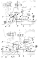
- Design options to bleed off some of the hydraulic medium from the annulus or siphon may take several different forms. Two preferred embodiments are shown in respective partial sectional views in the accompanying FIGS. 1 and 2 and are described more fully below. On the drawings, the reference numerals refer to the same components respectively.
- Reference numeral 1 indicates the first shaft and reference numeral 2 the second shaft of a two-shaft gas turbine aircraft engine, the two shafts rotating at different speeds (but preferably in the same sense of rotation) about the axis of rotation 3 of the engine.
- These shafts 1 and 2 here shown only in partial view, are conventionally arranged concentrically relative to one another, with the first shaft 1 , or low-pressure shaft, arranged inside the second shaft 2 , or high-pressure shaft.
- Reference numeral 4 indicates the movable bearing of high-pressure shaft 2 .
- a relatively low-pressure area N of the gas turbine interior Arranged on the right-hand side of movable bearing 4 and, viewed in radial direction R (which extends normal to rotational axis 3 ),outside of shaft 2 is a relatively low-pressure area N of the gas turbine interior, while arranged to the left side of expansion bearing 4 and, viewed in radial direction R, inside shaft 2 , is a relatively high-pressure area H.
- the two areas N and H must effectively be sealed one from the other, for which purpose a hydraulic seal arrangement generally indicated by the numeral 5 is provided between the two shafts 1 and 2 .
- This hydraulic seal arrangement 5 is essentially formed by an annulus 5 a which is provided in the interior of the outer shaft 2 and extends radially outwards in the direction R across the circumference of shaft 2 .
- Projecting into this annulus 5 a is a web 5 b which is arranged on the inner shaft 1 and extends again radially outwards in direction R across the circumference of shaft 1 .
- a large portion of annulus 5 a and especially that portion of it which surrounds the free end of web 5 b is filled or being filled with oil (from the engine's oil circuit) or generally with a hydraulic medium 5 c (indicated by the hatched area). The filling is done through an inlet area 5 d.
- hydraulic medium 5 c which in the form of an oil jet introduced between the two shafts 1 , 2 in the direction of arrowhead 6 is also used to lubricate movable bearing 4 , reaches annulus 5 a in the manner described below: Owing to the rotation of the two shafts 1 , 2 and the resulting centrifugal effect, hydraulic medium 5 c, introduced in the direction of arrowhead 6 as shown, collects on the inner wall 2 a of the outer shaft 2 , said inner wall lying radially outside with respect to the space between shafts 1 and 2 .
- Hydraulic medium 5 c in this manner enters, again under centrifugal effect, also annulus 5 a provided in shaft 2 , said annulus lying much further outward, when viewed in radial direction R, relative to that area of inner wall 2 a in which hydraulic medium 5 c is introduced in the direction of arrowhead 6 .
- hydraulic medium 5 c collects in annulus 5 a to both the left and the right sides of web 5 b, creating an optimum siphon-type hydraulic seal as shown.
- such a hydraulic seal arrangement 5 is basically reliable, but only when environmental temperatures are relatively low, so that there is no risk of coking of hydraulic medium 5 c, which in this application is oil taken from the gas turbine engine's oil circuit. But in that area of a gas turbine in which the hydraulic seal arrangement 5 as here described and explained is provided, temperatures are relatively high. More particularly, the material of the shafts 1 , 2 in this area picks up much heat, posing a risk inasmuch as the hydraulic medium 5 c in annulus 5 a may heat up enough to start coking.
- the two embodiments of the present invention provide means for exhausting some of the hydraulic medium 5 c from annulus 5 a, said means (differing in detail arrangement) being arranged in an annulus area 5 e that essentially is farthest away from inlet area 5 d.
- inlet area 5 d of annulus 5 a is in each embodiment located as far inside as possible, when viewed in radial direction R, whereas said annulus area 5 e having exhaust means for the hydraulic medium is located as far outside as possible, when viewed in radial direction R, and close to that side of annulus 5 a that lies opposite the inlet area 5 d.
- said means for exhausting part of the hydraulic medium 5 c takes the shape of at least one outlet duct 8 that passes through outer shaft 2 in essentially the direction of rotation axis 3 and is somewhat inclined in a radially outward direction. Through this outlet duct 8 a certain amount of hydraulic medium 5 c is continuously exhausted from annulus area 5 e. Continuous refilling of annulus 5 a is achieved as above described through the inlet area 5 d by means of an oil jet following the direction of arrow head 6 .
- fresh and hence relatively cold oil or hydraulic medium 5 c reaches the annulus 5 a (or the siphon of the hydraulic seal arrangement 5 ), while part of the hydraulic medium 5 c in annulus 5 a, heated by the environment, is being exhausted through the outlet duct 8 .
- the oil, or hydraulic medium 5 c accordingly remains in annulus 5 a for too short a period of time to coke.
- the essentially continuous flow of hydraulic medium 5 c through the annulus 5 a causes the containing walls of annulus 5 a to dissipate sufficient heat to cool these and avert the risk of coking from this source as well.
- the cross-sectional area of outlet duct 8 is selected such that the entire hydraulic medium 5 c present in annulus 5 a is renewed within a second.
- said means for exhausting part of the hydraulic medium 5 c takes the shape of scoop plate 9 which also begins in said annulus area 5 e and essentially follows the wall contour of annulus 5 a at a small distance therefrom to duct the hydraulic medium 5 c through a gap 10 formed by said distance into a radially further inward area from which an outlet duct 8 branches off which passes through outer shaft 2 and leads to the outside in an essentially radial direction R.
- outlet duct 8 and gap 10 both have a larger cross-sectional area than the outlet duct 8 of the embodiment according to FIG. 1 .
- the embodiment of FIG. 2 prevents outlet duct 8 from clogging, which under adverse conditions might happen in the embodiment in accordance with FIG. 1 .
- the cross-sectional area of outlet duct 8 should not be excessively large, so that the amount of hydraulic medium 5 c remaining in annulus 5 a will always be sufficient (for the desired sealing action). Since in the embodiment in accordance with FIG. 2 outlet duct 8 lies further inward, when viewed in radial direction R, than in the embodiment in accordance with FIG. 1, the free flow area of outlet duct 8 (and of gap 10 ) can as a result of the lower centrifugal action naturally be wider in FIG. 2 than in FIG. 1 .
- outlet duct 8 issues into area N of the gas turbine interior, where the pressure is relatively low.
- said area H of the gas turbine interior, in which the pressure is relatively high is sealed off from area N, or from annulus 5 a, by hydraulic seal arrangement 5 and additionally by a seal ring 11 (taking the form of a piston ring for example) arranged between the two shafts 1 , 2 .
- This seal ring 11 will be effective only when shafts 1 , 2 are standing still, whereas when shafts 1 , 2 are rotating, the sealing action is prevented by centrifugal effects, so that hydraulic seal arrangement 5 is needed.
- a plurality of design or other details may deviate from the embodiments shown without detracting from the substance of the patent claims.
Landscapes
- Engineering & Computer Science (AREA)
- General Engineering & Computer Science (AREA)
- Mechanical Engineering (AREA)
- Sealing Using Fluids, Sealing Without Contact, And Removal Of Oil (AREA)
Abstract
Description
Claims (10)
Applications Claiming Priority (2)
| Application Number | Priority Date | Filing Date | Title |
|---|---|---|---|
| DE19916803 | 1999-04-14 | ||
| DE19916803A DE19916803A1 (en) | 1999-04-14 | 1999-04-14 | Hydraulic sealing arrangement, in particular on a gas turbine |
Publications (1)
| Publication Number | Publication Date |
|---|---|
| US6568688B1 true US6568688B1 (en) | 2003-05-27 |
Family
ID=7904511
Family Applications (1)
| Application Number | Title | Priority Date | Filing Date |
|---|---|---|---|
| US09/550,309 Expired - Fee Related US6568688B1 (en) | 1999-04-14 | 2000-04-14 | Hydraulic seal arrangement, more particularly on a gas turbine |
Country Status (3)
| Country | Link |
|---|---|
| US (1) | US6568688B1 (en) |
| EP (1) | EP1045178B1 (en) |
| DE (2) | DE19916803A1 (en) |
Cited By (22)
| Publication number | Priority date | Publication date | Assignee | Title |
|---|---|---|---|---|
| US20030168815A1 (en) * | 2002-01-14 | 2003-09-11 | Detlef Rensch | Hydraulic seal arrangement |
| US20040046325A1 (en) * | 2002-09-10 | 2004-03-11 | Mccutchan Sean | Shaft seal |
| US20040179935A1 (en) * | 2003-03-15 | 2004-09-16 | Alan Maguire | Seal |
| US20040188945A1 (en) * | 2001-09-14 | 2004-09-30 | Michel Poincet | Sealing device |
| EP1531294A1 (en) * | 2003-11-12 | 2005-05-18 | United Technologies Corporation | Shaft seal |
| US20060024166A1 (en) * | 2004-07-28 | 2006-02-02 | Richard Whitton | Gas turbine rotor |
| US20060033289A1 (en) * | 2004-08-13 | 2006-02-16 | Miklos Gaebler | Hydraulic shaft sealing arrangement for high-temperature applications |
| US20070271914A1 (en) * | 2006-05-10 | 2007-11-29 | Andreas Bar | Transmission having a coaxial lubricant pump |
| US20090189356A1 (en) * | 2007-12-14 | 2009-07-30 | Miklos Gaebler | Sealing of at least one shaft by at least one hydraulic seal |
| US20090238691A1 (en) * | 2006-11-28 | 2009-09-24 | Purdey Matthew J | Hydraulic Seal for a turbocharger |
| US20100090415A1 (en) * | 2008-10-14 | 2010-04-15 | Rolls-Royce Plc | Seal |
| US20120248707A1 (en) * | 2011-03-29 | 2012-10-04 | Rolls-Royce Plc | Assembly comprising a rotatable component |
| RU2489590C1 (en) * | 2012-02-29 | 2013-08-10 | Открытое акционерное общество "Научно-производственное объединение "Сатурн" (ОАО "НПО "Сатурн") | Turbomachine |
| US20140158232A1 (en) * | 2012-12-06 | 2014-06-12 | Rolls-Royce Plc | A hydraulic seal arrangement |
| US20160348792A1 (en) * | 2015-05-26 | 2016-12-01 | Pratt & Whitney Canada Corp. | Internally cooled seal runner and method of cooling seal runner of a gas turbine engine |
| EP3112729A1 (en) * | 2015-06-30 | 2017-01-04 | Rolls-Royce plc | A seal |
| US20170370288A1 (en) * | 2016-06-28 | 2017-12-28 | Rolls-Royce Deutschland Ltd & Co Kg | Oil distribution system and turbomachine with an oil distribution system |
| US10371263B2 (en) | 2017-06-23 | 2019-08-06 | United Technologies Corporation | Hydraulic seal for non-mainshaft, rotating to static |
| US10502096B2 (en) | 2017-12-15 | 2019-12-10 | General Electric Company | Bearing damper for cold engine ground starts or in-flight re-starts |
| US20200300117A1 (en) * | 2019-03-18 | 2020-09-24 | United Technologies Corporation | Seal assembly for a gas turbine engine |
| US11486411B2 (en) | 2018-12-14 | 2022-11-01 | Cummins Ltd. | Seal assembly |
| US20230003226A1 (en) * | 2019-12-16 | 2023-01-05 | Ebara Corporation | Pump and rotary baffle plate |
Families Citing this family (8)
| Publication number | Priority date | Publication date | Assignee | Title |
|---|---|---|---|---|
| US7334982B2 (en) * | 2005-05-06 | 2008-02-26 | General Electric Company | Apparatus for scavenging lubricating oil |
| DE102005047696A1 (en) * | 2005-09-27 | 2007-03-29 | Rolls-Royce Deutschland Ltd & Co Kg | Siphon-like hydraulic seal for use between e.g. high- and low pressure shafts of aircraft engine, has locking bar movably and axially held at circumference of inner shaft and formed in rotational direction of hydraulic fluid barrier |
| DE102009054007B4 (en) * | 2009-11-19 | 2018-02-08 | Rolls-Royce Deutschland Ltd & Co Kg | Gas turbine with hydraulic seal |
| DE102011122109A1 (en) * | 2011-12-22 | 2013-06-27 | Rolls-Royce Deutschland Ltd & Co Kg | Seal arrangement for turbo machine i.e. airplane engine, for sealing bearing devices, has fluid guide elements plunged in region in reservoir, and sealing unit includes oil inflow and oil drain, where inflow and drain lie in pressure region |
| DE102012011144A1 (en) | 2012-06-05 | 2013-12-05 | Rolls-Royce Deutschland Ltd & Co Kg | Hydraulic seal arrangement |
| DE102017110064A1 (en) * | 2017-05-10 | 2018-11-15 | Rolls-Royce Deutschland Ltd & Co Kg | A gas turbine engine and method for providing damping between a first shaft and a second coaxial rotating shaft |
| US11028717B2 (en) * | 2017-06-26 | 2021-06-08 | Raytheon Technologies Corporation | Bearing assembly for gas turbine engines |
| FR3123702B1 (en) | 2021-06-04 | 2023-04-28 | Safran Helicopter Engines | HYDRAULIC SEAL SYSTEM WITH LIP FEED |
Citations (16)
| Publication number | Priority date | Publication date | Assignee | Title |
|---|---|---|---|---|
| US822802A (en) * | 1905-11-24 | 1906-06-05 | Wilkinson Turbine Company | Shaft-packing. |
| US2284465A (en) * | 1940-11-25 | 1942-05-26 | Gen Electric | Shaft packing |
| US2573425A (en) | 1947-06-23 | 1951-10-30 | Ethel K Haferkamp | Seal for centrifugal machines |
| GB848601A (en) | 1958-07-17 | 1960-09-21 | Davidson & Co Ltd | Improvements in or relating to seals for rotary shafts |
| US2960356A (en) | 1959-03-06 | 1960-11-15 | Tyce Engineering Corp | Hydrodynamic rotary shaft seals |
| GB1212593A (en) | 1968-01-25 | 1970-11-18 | British Aircraft Corp Ltd | Improvements relating to rotary large diameter gas seals |
| GB1284596A (en) | 1969-12-20 | 1972-08-09 | Rolls Royce | Improvements in or relating to hydraulic seals |
| US3765688A (en) | 1971-07-19 | 1973-10-16 | Avco Corp | High speed shaft centrifuge fluid seal |
| US3880434A (en) | 1973-01-29 | 1975-04-29 | Commissariat Energie Atomique | Sealing device for shaft of machines |
| DE2559667A1 (en) | 1975-08-02 | 1977-11-17 | Hermann Ernst | Shaft seal for centrifugal pump - has laminations mounted in recess of shaft flange to return leakage to pump housing |
| DE3328057A1 (en) | 1982-08-03 | 1984-02-09 | Rolls-Royce Ltd., London | LIQUID RING SEAL |
| US4795167A (en) * | 1987-06-26 | 1989-01-03 | Eagle Industry Co., Ltd. | Mechanical seal |
| FR2621970A1 (en) | 1987-10-20 | 1989-04-21 | Hebert Michel | Dynamic sealing device using a centrifugal body |
| US5984630A (en) * | 1997-12-24 | 1999-11-16 | General Electric Company | Reduced windage high pressure turbine forward outer seal |
| US6155574A (en) * | 1996-11-05 | 2000-12-05 | Alfa Laval Ab | Sealing device |
| US6170832B1 (en) * | 1998-03-26 | 2001-01-09 | Hermann H. F. Ernst | Fluid ring seal system and method |
-
1999
- 1999-04-14 DE DE19916803A patent/DE19916803A1/en not_active Withdrawn
-
2000
- 2000-03-27 EP EP00106564A patent/EP1045178B1/en not_active Expired - Lifetime
- 2000-03-27 DE DE50010259T patent/DE50010259D1/en not_active Expired - Lifetime
- 2000-04-14 US US09/550,309 patent/US6568688B1/en not_active Expired - Fee Related
Patent Citations (17)
| Publication number | Priority date | Publication date | Assignee | Title |
|---|---|---|---|---|
| US822802A (en) * | 1905-11-24 | 1906-06-05 | Wilkinson Turbine Company | Shaft-packing. |
| US2284465A (en) * | 1940-11-25 | 1942-05-26 | Gen Electric | Shaft packing |
| US2573425A (en) | 1947-06-23 | 1951-10-30 | Ethel K Haferkamp | Seal for centrifugal machines |
| GB848601A (en) | 1958-07-17 | 1960-09-21 | Davidson & Co Ltd | Improvements in or relating to seals for rotary shafts |
| US2960356A (en) | 1959-03-06 | 1960-11-15 | Tyce Engineering Corp | Hydrodynamic rotary shaft seals |
| GB1212593A (en) | 1968-01-25 | 1970-11-18 | British Aircraft Corp Ltd | Improvements relating to rotary large diameter gas seals |
| GB1284596A (en) | 1969-12-20 | 1972-08-09 | Rolls Royce | Improvements in or relating to hydraulic seals |
| US3765688A (en) | 1971-07-19 | 1973-10-16 | Avco Corp | High speed shaft centrifuge fluid seal |
| US3880434A (en) | 1973-01-29 | 1975-04-29 | Commissariat Energie Atomique | Sealing device for shaft of machines |
| DE2559667A1 (en) | 1975-08-02 | 1977-11-17 | Hermann Ernst | Shaft seal for centrifugal pump - has laminations mounted in recess of shaft flange to return leakage to pump housing |
| DE3328057A1 (en) | 1982-08-03 | 1984-02-09 | Rolls-Royce Ltd., London | LIQUID RING SEAL |
| GB2125118A (en) | 1982-08-03 | 1984-02-29 | Rolls Royce | Hydraulic seal |
| US4795167A (en) * | 1987-06-26 | 1989-01-03 | Eagle Industry Co., Ltd. | Mechanical seal |
| FR2621970A1 (en) | 1987-10-20 | 1989-04-21 | Hebert Michel | Dynamic sealing device using a centrifugal body |
| US6155574A (en) * | 1996-11-05 | 2000-12-05 | Alfa Laval Ab | Sealing device |
| US5984630A (en) * | 1997-12-24 | 1999-11-16 | General Electric Company | Reduced windage high pressure turbine forward outer seal |
| US6170832B1 (en) * | 1998-03-26 | 2001-01-09 | Hermann H. F. Ernst | Fluid ring seal system and method |
Cited By (41)
| Publication number | Priority date | Publication date | Assignee | Title |
|---|---|---|---|---|
| US20040188945A1 (en) * | 2001-09-14 | 2004-09-30 | Michel Poincet | Sealing device |
| US6921079B2 (en) | 2002-01-14 | 2005-07-26 | Rolls-Royce Deutschland Ltd & Co Kg | Hydraulic seal arrangement |
| US20030168815A1 (en) * | 2002-01-14 | 2003-09-11 | Detlef Rensch | Hydraulic seal arrangement |
| US20040046325A1 (en) * | 2002-09-10 | 2004-03-11 | Mccutchan Sean | Shaft seal |
| US6845987B2 (en) * | 2002-09-10 | 2005-01-25 | United Technologies Corporation | Shaft seal |
| US20050098956A1 (en) * | 2002-09-10 | 2005-05-12 | United Technologies Corporation | Shaft seal |
| US7159873B2 (en) * | 2002-09-10 | 2007-01-09 | United Technologies Corporation | Shaft seal |
| US20040179935A1 (en) * | 2003-03-15 | 2004-09-16 | Alan Maguire | Seal |
| US20050230922A1 (en) * | 2003-03-15 | 2005-10-20 | Maguire Alan R | Seal |
| EP1531294A1 (en) * | 2003-11-12 | 2005-05-18 | United Technologies Corporation | Shaft seal |
| US7874803B2 (en) | 2004-07-28 | 2011-01-25 | Rolls-Royce Deutschland Ltd & Co Kg | Gas turbine rotor |
| US20060024166A1 (en) * | 2004-07-28 | 2006-02-02 | Richard Whitton | Gas turbine rotor |
| US20060033289A1 (en) * | 2004-08-13 | 2006-02-16 | Miklos Gaebler | Hydraulic shaft sealing arrangement for high-temperature applications |
| US7344139B2 (en) | 2004-08-13 | 2008-03-18 | Rolls-Royce Deutschland Ltd & Co Kg | Hydraulic shaft sealing arrangement for high-temperature applications |
| US20070271914A1 (en) * | 2006-05-10 | 2007-11-29 | Andreas Bar | Transmission having a coaxial lubricant pump |
| US7757816B2 (en) | 2006-05-10 | 2010-07-20 | Magna Powertrain Ag & Co Kg | Transmission having a coaxial lubricant pump |
| US20090238691A1 (en) * | 2006-11-28 | 2009-09-24 | Purdey Matthew J | Hydraulic Seal for a turbocharger |
| US8075251B2 (en) | 2006-11-28 | 2011-12-13 | Cummins Turbo Technologies Limited | Hydraulic seal for a turbocharger |
| US20090189356A1 (en) * | 2007-12-14 | 2009-07-30 | Miklos Gaebler | Sealing of at least one shaft by at least one hydraulic seal |
| US8444153B2 (en) | 2007-12-14 | 2013-05-21 | Rolls-Royce Deutschland Ltd & Co Kg | Sealing of at least one shaft by at least one hydraulic seal |
| US9133939B2 (en) | 2008-10-14 | 2015-09-15 | Rolls-Royce Plc | Seal |
| EP2177795A1 (en) | 2008-10-14 | 2010-04-21 | Rolls-Royce plc | A seal |
| US20100090415A1 (en) * | 2008-10-14 | 2010-04-15 | Rolls-Royce Plc | Seal |
| JP2010107038A (en) * | 2008-10-14 | 2010-05-13 | Rolls Royce Plc | Seal |
| US20120248707A1 (en) * | 2011-03-29 | 2012-10-04 | Rolls-Royce Plc | Assembly comprising a rotatable component |
| US8840114B2 (en) * | 2011-03-29 | 2014-09-23 | Rolls-Royce Plc | Assembly comprising a rotatable component |
| RU2489590C1 (en) * | 2012-02-29 | 2013-08-10 | Открытое акционерное общество "Научно-производственное объединение "Сатурн" (ОАО "НПО "Сатурн") | Turbomachine |
| US20140158232A1 (en) * | 2012-12-06 | 2014-06-12 | Rolls-Royce Plc | A hydraulic seal arrangement |
| US9157532B2 (en) * | 2012-12-06 | 2015-10-13 | Rolls-Royce Plc | Hydraulic seal arrangement |
| US10753219B2 (en) * | 2015-05-26 | 2020-08-25 | Pratt & Whitney Canada Corp. | Internally cooled seal runner and method of cooling seal runner of a gas turbine engine |
| US20160348792A1 (en) * | 2015-05-26 | 2016-12-01 | Pratt & Whitney Canada Corp. | Internally cooled seal runner and method of cooling seal runner of a gas turbine engine |
| EP3112729A1 (en) * | 2015-06-30 | 2017-01-04 | Rolls-Royce plc | A seal |
| US10119420B2 (en) | 2015-06-30 | 2018-11-06 | Rolls-Royce Plc | Seal |
| US20170370288A1 (en) * | 2016-06-28 | 2017-12-28 | Rolls-Royce Deutschland Ltd & Co Kg | Oil distribution system and turbomachine with an oil distribution system |
| US10371263B2 (en) | 2017-06-23 | 2019-08-06 | United Technologies Corporation | Hydraulic seal for non-mainshaft, rotating to static |
| US10502096B2 (en) | 2017-12-15 | 2019-12-10 | General Electric Company | Bearing damper for cold engine ground starts or in-flight re-starts |
| US11486411B2 (en) | 2018-12-14 | 2022-11-01 | Cummins Ltd. | Seal assembly |
| US20200300117A1 (en) * | 2019-03-18 | 2020-09-24 | United Technologies Corporation | Seal assembly for a gas turbine engine |
| US11248492B2 (en) * | 2019-03-18 | 2022-02-15 | Raytheon Technologies Corporation | Seal assembly for a gas turbine engine |
| US20230003226A1 (en) * | 2019-12-16 | 2023-01-05 | Ebara Corporation | Pump and rotary baffle plate |
| US11913466B2 (en) * | 2019-12-16 | 2024-02-27 | Ebara Corporation | Pump and rotary baffle plate |
Also Published As
| Publication number | Publication date |
|---|---|
| DE19916803A1 (en) | 2000-10-19 |
| EP1045178A2 (en) | 2000-10-18 |
| DE50010259D1 (en) | 2005-06-16 |
| EP1045178B1 (en) | 2005-05-11 |
| EP1045178A3 (en) | 2002-09-11 |
Similar Documents
| Publication | Publication Date | Title |
|---|---|---|
| US6568688B1 (en) | Hydraulic seal arrangement, more particularly on a gas turbine | |
| US7121791B2 (en) | Main gas duct internal seal of a high-pressure turbine | |
| EP1508671B1 (en) | A brush seal for gas turbine engines | |
| US5301957A (en) | Expanding circumferential seal with upper-cooled runner | |
| US5188506A (en) | Apparatus and method for preventing leakage of cooling air in a shroud assembly of a gas turbine engine | |
| US7021631B2 (en) | Seal arrangement | |
| US6921079B2 (en) | Hydraulic seal arrangement | |
| US5244345A (en) | Rotor | |
| US6293089B1 (en) | Gas turbine | |
| US8277177B2 (en) | Fluidic rim seal system for turbine engines | |
| RU2132474C1 (en) | Bearing support ring unit (design versions) | |
| US10012101B2 (en) | Seal system for a gas turbine | |
| US6401896B1 (en) | Lubricating device for wet multi-disk clutch | |
| US3446482A (en) | Liquid cooled turbine rotor | |
| EP3702586B1 (en) | Gas turbine engine including seal plate providing increased cooling adjacent contact area | |
| RU2271454C2 (en) | Making of platforms in straight-flow axial gas turbine with improved cooling of wall sections and method of decreasing losses through clearances | |
| US6416276B1 (en) | Heat shield device in gas turbines | |
| US7344139B2 (en) | Hydraulic shaft sealing arrangement for high-temperature applications | |
| GB2091356A (en) | Oil seal device for rotary machines | |
| US8057163B2 (en) | Gas turbine engine cooling system and method | |
| RU2358132C2 (en) | Lubricating device for lubrication of turbo-machine elements and turbojet engine | |
| JPH07503298A (en) | Coolable outer air seal device for turbines | |
| EP2177795B1 (en) | A seal | |
| JPH10274003A (en) | Seal device for gas turbine | |
| US9765629B2 (en) | Method and cooling system for cooling blades of at least one blade row in a rotary flow machine |
Legal Events
| Date | Code | Title | Description |
|---|---|---|---|
| AS | Assignment |
Owner name: ROLLS-ROYCE DEUTSCHLAND GMBH, GERMANY Free format text: ASSIGNMENT OF ASSIGNORS INTEREST;ASSIGNOR:BOECK, ALEXANDER;REEL/FRAME:011258/0932 Effective date: 20000526 |
|
| AS | Assignment |
Owner name: ROLLS-ROYCE DEUTSCHLAND GMBH, GERMANY Free format text: CHANGE OF NAME;ASSIGNOR:BMW ROLLS-ROYCE GMBH;REEL/FRAME:013457/0020 Effective date: 20000131 |
|
| AS | Assignment |
Owner name: ROLLS-ROYCE DEUTSCHLAND LTD & CO KG, GERMANY Free format text: CHANGE OF NAME;ASSIGNOR:ROLLS-ROYCE DEUTSCHLAND GMBH;REEL/FRAME:013190/0381 Effective date: 20001120 |
|
| FPAY | Fee payment |
Year of fee payment: 4 |
|
| FPAY | Fee payment |
Year of fee payment: 8 |
|
| REMI | Maintenance fee reminder mailed | ||
| LAPS | Lapse for failure to pay maintenance fees | ||
| STCH | Information on status: patent discontinuation |
Free format text: PATENT EXPIRED DUE TO NONPAYMENT OF MAINTENANCE FEES UNDER 37 CFR 1.362 |
|
| FP | Lapsed due to failure to pay maintenance fee |
Effective date: 20150527 |