EP3702586B1 - Gas turbine engine including seal plate providing increased cooling adjacent contact area - Google Patents
Gas turbine engine including seal plate providing increased cooling adjacent contact area Download PDFInfo
- Publication number
- EP3702586B1 EP3702586B1 EP20159549.3A EP20159549A EP3702586B1 EP 3702586 B1 EP3702586 B1 EP 3702586B1 EP 20159549 A EP20159549 A EP 20159549A EP 3702586 B1 EP3702586 B1 EP 3702586B1
- Authority
- EP
- European Patent Office
- Prior art keywords
- section
- circumferentially
- gas turbine
- turbine engine
- recited
- Prior art date
- Legal status (The legal status is an assumption and is not a legal conclusion. Google has not performed a legal analysis and makes no representation as to the accuracy of the status listed.)
- Active
Links
- 238000001816 cooling Methods 0.000 title claims description 38
- 239000012530 fluid Substances 0.000 claims description 19
- 239000012809 cooling fluid Substances 0.000 claims description 12
- 239000003575 carbonaceous material Substances 0.000 claims description 2
- 239000000446 fuel Substances 0.000 description 5
- 238000004519 manufacturing process Methods 0.000 description 5
- 238000000034 method Methods 0.000 description 4
- 230000007704 transition Effects 0.000 description 4
- 239000000463 material Substances 0.000 description 3
- 239000003921 oil Substances 0.000 description 3
- 230000003068 static effect Effects 0.000 description 3
- 238000012546 transfer Methods 0.000 description 3
- 230000008859 change Effects 0.000 description 2
- 239000000203 mixture Substances 0.000 description 2
- 230000009467 reduction Effects 0.000 description 2
- OKTJSMMVPCPJKN-UHFFFAOYSA-N Carbon Chemical compound [C] OKTJSMMVPCPJKN-UHFFFAOYSA-N 0.000 description 1
- 239000000654 additive Substances 0.000 description 1
- 230000000996 additive effect Effects 0.000 description 1
- 230000000712 assembly Effects 0.000 description 1
- 238000000429 assembly Methods 0.000 description 1
- 230000003416 augmentation Effects 0.000 description 1
- 238000005219 brazing Methods 0.000 description 1
- 229910052799 carbon Inorganic materials 0.000 description 1
- 238000004891 communication Methods 0.000 description 1
- 230000006835 compression Effects 0.000 description 1
- 238000007906 compression Methods 0.000 description 1
- 239000000356 contaminant Substances 0.000 description 1
- 238000012937 correction Methods 0.000 description 1
- 230000001419 dependent effect Effects 0.000 description 1
- 238000005553 drilling Methods 0.000 description 1
- 238000005495 investment casting Methods 0.000 description 1
- 239000000314 lubricant Substances 0.000 description 1
- 239000010687 lubricating oil Substances 0.000 description 1
- 230000007246 mechanism Effects 0.000 description 1
- 238000003801 milling Methods 0.000 description 1
- 239000003595 mist Substances 0.000 description 1
- 238000012986 modification Methods 0.000 description 1
- 230000004048 modification Effects 0.000 description 1
- 230000004044 response Effects 0.000 description 1
- 238000005096 rolling process Methods 0.000 description 1
- 239000013585 weight reducing agent Substances 0.000 description 1
- 238000003466 welding Methods 0.000 description 1
Images


Classifications
-
- F—MECHANICAL ENGINEERING; LIGHTING; HEATING; WEAPONS; BLASTING
- F01—MACHINES OR ENGINES IN GENERAL; ENGINE PLANTS IN GENERAL; STEAM ENGINES
- F01D—NON-POSITIVE DISPLACEMENT MACHINES OR ENGINES, e.g. STEAM TURBINES
- F01D25/00—Component parts, details, or accessories, not provided for in, or of interest apart from, other groups
- F01D25/08—Cooling; Heating; Heat-insulation
- F01D25/12—Cooling
- F01D25/125—Cooling of bearings
-
- F—MECHANICAL ENGINEERING; LIGHTING; HEATING; WEAPONS; BLASTING
- F01—MACHINES OR ENGINES IN GENERAL; ENGINE PLANTS IN GENERAL; STEAM ENGINES
- F01D—NON-POSITIVE DISPLACEMENT MACHINES OR ENGINES, e.g. STEAM TURBINES
- F01D11/00—Preventing or minimising internal leakage of working-fluid, e.g. between stages
- F01D11/003—Preventing or minimising internal leakage of working-fluid, e.g. between stages by packing rings; Mechanical seals
-
- F—MECHANICAL ENGINEERING; LIGHTING; HEATING; WEAPONS; BLASTING
- F01—MACHINES OR ENGINES IN GENERAL; ENGINE PLANTS IN GENERAL; STEAM ENGINES
- F01D—NON-POSITIVE DISPLACEMENT MACHINES OR ENGINES, e.g. STEAM TURBINES
- F01D25/00—Component parts, details, or accessories, not provided for in, or of interest apart from, other groups
- F01D25/08—Cooling; Heating; Heat-insulation
- F01D25/12—Cooling
-
- F—MECHANICAL ENGINEERING; LIGHTING; HEATING; WEAPONS; BLASTING
- F01—MACHINES OR ENGINES IN GENERAL; ENGINE PLANTS IN GENERAL; STEAM ENGINES
- F01D—NON-POSITIVE DISPLACEMENT MACHINES OR ENGINES, e.g. STEAM TURBINES
- F01D25/00—Component parts, details, or accessories, not provided for in, or of interest apart from, other groups
- F01D25/16—Arrangement of bearings; Supporting or mounting bearings in casings
-
- F—MECHANICAL ENGINEERING; LIGHTING; HEATING; WEAPONS; BLASTING
- F01—MACHINES OR ENGINES IN GENERAL; ENGINE PLANTS IN GENERAL; STEAM ENGINES
- F01D—NON-POSITIVE DISPLACEMENT MACHINES OR ENGINES, e.g. STEAM TURBINES
- F01D25/00—Component parts, details, or accessories, not provided for in, or of interest apart from, other groups
- F01D25/18—Lubricating arrangements
- F01D25/183—Sealing means
-
- F—MECHANICAL ENGINEERING; LIGHTING; HEATING; WEAPONS; BLASTING
- F04—POSITIVE - DISPLACEMENT MACHINES FOR LIQUIDS; PUMPS FOR LIQUIDS OR ELASTIC FLUIDS
- F04D—NON-POSITIVE-DISPLACEMENT PUMPS
- F04D29/00—Details, component parts, or accessories
- F04D29/08—Sealings
- F04D29/10—Shaft sealings
- F04D29/12—Shaft sealings using sealing-rings
- F04D29/122—Shaft sealings using sealing-rings especially adapted for elastic fluid pumps
- F04D29/124—Shaft sealings using sealing-rings especially adapted for elastic fluid pumps with special means for adducting cooling or sealing fluid
-
- F—MECHANICAL ENGINEERING; LIGHTING; HEATING; WEAPONS; BLASTING
- F16—ENGINEERING ELEMENTS AND UNITS; GENERAL MEASURES FOR PRODUCING AND MAINTAINING EFFECTIVE FUNCTIONING OF MACHINES OR INSTALLATIONS; THERMAL INSULATION IN GENERAL
- F16C—SHAFTS; FLEXIBLE SHAFTS; ELEMENTS OR CRANKSHAFT MECHANISMS; ROTARY BODIES OTHER THAN GEARING ELEMENTS; BEARINGS
- F16C33/00—Parts of bearings; Special methods for making bearings or parts thereof
- F16C33/72—Sealings
-
- F—MECHANICAL ENGINEERING; LIGHTING; HEATING; WEAPONS; BLASTING
- F16—ENGINEERING ELEMENTS AND UNITS; GENERAL MEASURES FOR PRODUCING AND MAINTAINING EFFECTIVE FUNCTIONING OF MACHINES OR INSTALLATIONS; THERMAL INSULATION IN GENERAL
- F16C—SHAFTS; FLEXIBLE SHAFTS; ELEMENTS OR CRANKSHAFT MECHANISMS; ROTARY BODIES OTHER THAN GEARING ELEMENTS; BEARINGS
- F16C37/00—Cooling of bearings
-
- F—MECHANICAL ENGINEERING; LIGHTING; HEATING; WEAPONS; BLASTING
- F16—ENGINEERING ELEMENTS AND UNITS; GENERAL MEASURES FOR PRODUCING AND MAINTAINING EFFECTIVE FUNCTIONING OF MACHINES OR INSTALLATIONS; THERMAL INSULATION IN GENERAL
- F16J—PISTONS; CYLINDERS; SEALINGS
- F16J15/00—Sealings
- F16J15/16—Sealings between relatively-moving surfaces
- F16J15/34—Sealings between relatively-moving surfaces with slip-ring pressed against a more or less radial face on one member
- F16J15/3404—Sealings between relatively-moving surfaces with slip-ring pressed against a more or less radial face on one member and characterised by parts or details relating to lubrication, cooling or venting of the seal
-
- F—MECHANICAL ENGINEERING; LIGHTING; HEATING; WEAPONS; BLASTING
- F01—MACHINES OR ENGINES IN GENERAL; ENGINE PLANTS IN GENERAL; STEAM ENGINES
- F01D—NON-POSITIVE DISPLACEMENT MACHINES OR ENGINES, e.g. STEAM TURBINES
- F01D25/00—Component parts, details, or accessories, not provided for in, or of interest apart from, other groups
- F01D25/16—Arrangement of bearings; Supporting or mounting bearings in casings
- F01D25/162—Bearing supports
-
- F—MECHANICAL ENGINEERING; LIGHTING; HEATING; WEAPONS; BLASTING
- F01—MACHINES OR ENGINES IN GENERAL; ENGINE PLANTS IN GENERAL; STEAM ENGINES
- F01D—NON-POSITIVE DISPLACEMENT MACHINES OR ENGINES, e.g. STEAM TURBINES
- F01D25/00—Component parts, details, or accessories, not provided for in, or of interest apart from, other groups
- F01D25/18—Lubricating arrangements
-
- F—MECHANICAL ENGINEERING; LIGHTING; HEATING; WEAPONS; BLASTING
- F05—INDEXING SCHEMES RELATING TO ENGINES OR PUMPS IN VARIOUS SUBCLASSES OF CLASSES F01-F04
- F05D—INDEXING SCHEME FOR ASPECTS RELATING TO NON-POSITIVE-DISPLACEMENT MACHINES OR ENGINES, GAS-TURBINES OR JET-PROPULSION PLANTS
- F05D2240/00—Components
- F05D2240/55—Seals
-
- F—MECHANICAL ENGINEERING; LIGHTING; HEATING; WEAPONS; BLASTING
- F05—INDEXING SCHEMES RELATING TO ENGINES OR PUMPS IN VARIOUS SUBCLASSES OF CLASSES F01-F04
- F05D—INDEXING SCHEME FOR ASPECTS RELATING TO NON-POSITIVE-DISPLACEMENT MACHINES OR ENGINES, GAS-TURBINES OR JET-PROPULSION PLANTS
- F05D2260/00—Function
- F05D2260/20—Heat transfer, e.g. cooling
-
- F—MECHANICAL ENGINEERING; LIGHTING; HEATING; WEAPONS; BLASTING
- F16—ENGINEERING ELEMENTS AND UNITS; GENERAL MEASURES FOR PRODUCING AND MAINTAINING EFFECTIVE FUNCTIONING OF MACHINES OR INSTALLATIONS; THERMAL INSULATION IN GENERAL
- F16C—SHAFTS; FLEXIBLE SHAFTS; ELEMENTS OR CRANKSHAFT MECHANISMS; ROTARY BODIES OTHER THAN GEARING ELEMENTS; BEARINGS
- F16C33/00—Parts of bearings; Special methods for making bearings or parts thereof
- F16C33/30—Parts of ball or roller bearings
- F16C33/66—Special parts or details in view of lubrication
- F16C33/6637—Special parts or details in view of lubrication with liquid lubricant
- F16C33/6659—Details of supply of the liquid to the bearing, e.g. passages or nozzles
- F16C33/6677—Details of supply of the liquid to the bearing, e.g. passages or nozzles from radial inside, e.g. via a passage through the shaft and/or inner ring
-
- F—MECHANICAL ENGINEERING; LIGHTING; HEATING; WEAPONS; BLASTING
- F16—ENGINEERING ELEMENTS AND UNITS; GENERAL MEASURES FOR PRODUCING AND MAINTAINING EFFECTIVE FUNCTIONING OF MACHINES OR INSTALLATIONS; THERMAL INSULATION IN GENERAL
- F16J—PISTONS; CYLINDERS; SEALINGS
- F16J15/00—Sealings
- F16J15/16—Sealings between relatively-moving surfaces
- F16J15/34—Sealings between relatively-moving surfaces with slip-ring pressed against a more or less radial face on one member
- F16J15/3404—Sealings between relatively-moving surfaces with slip-ring pressed against a more or less radial face on one member and characterised by parts or details relating to lubrication, cooling or venting of the seal
- F16J15/3408—Sealings between relatively-moving surfaces with slip-ring pressed against a more or less radial face on one member and characterised by parts or details relating to lubrication, cooling or venting of the seal at least one ring having an uneven slipping surface
- F16J15/3412—Sealings between relatively-moving surfaces with slip-ring pressed against a more or less radial face on one member and characterised by parts or details relating to lubrication, cooling or venting of the seal at least one ring having an uneven slipping surface with cavities
- F16J15/342—Sealings between relatively-moving surfaces with slip-ring pressed against a more or less radial face on one member and characterised by parts or details relating to lubrication, cooling or venting of the seal at least one ring having an uneven slipping surface with cavities with means for feeding fluid directly to the face
-
- Y—GENERAL TAGGING OF NEW TECHNOLOGICAL DEVELOPMENTS; GENERAL TAGGING OF CROSS-SECTIONAL TECHNOLOGIES SPANNING OVER SEVERAL SECTIONS OF THE IPC; TECHNICAL SUBJECTS COVERED BY FORMER USPC CROSS-REFERENCE ART COLLECTIONS [XRACs] AND DIGESTS
- Y02—TECHNOLOGIES OR APPLICATIONS FOR MITIGATION OR ADAPTATION AGAINST CLIMATE CHANGE
- Y02T—CLIMATE CHANGE MITIGATION TECHNOLOGIES RELATED TO TRANSPORTATION
- Y02T50/00—Aeronautics or air transport
- Y02T50/60—Efficient propulsion technologies, e.g. for aircraft
Definitions
- a gas turbine engine typically includes a fan section, a compressor section, a combustor section, and a turbine section. Air entering the compressor section is compressed and delivered into the combustor section where it is mixed with fuel and ignited to generate a high-speed exhaust gas flow. The high-speed exhaust gas flow expands through the turbine section to drive the compressor and the fan section.
- the compressor section typically includes low and high pressure compressors, and the turbine section includes low and high pressure turbines.
- a gas turbine engine also includes bearings that support rotatable shafts.
- the bearings require lubricant.
- Various seals near the rotating shafts contain oil within bearing compartments, which include bearings and seals.
- non-rotating seal faces contact rotating seal plates to maintain compartment pressures and keep lubricating oil inside the various compartments. Friction between the seals and seal plates generates heat and exposes the seals to relatively high temperatures.
- carbon materials have been used to increase seal wear life.
- a seal plate is cooled with a flow of cooling fluid, which increases heat transfer away from the seal and reduces seal operating temperature.
- EP 3382240 A1 discloses a gas turbine engine having the features of the preamble of claim 1.
- EP 3282153 A1 discloses a hydrodynamic seal seat cooling feature.
- US 2990202 A discloses a labyrinth face seal plate.
- a gas turbine engine according to a first aspect of the present invention is claimed in claim 1.
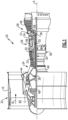
- FIG. 1 schematically illustrates a gas turbine engine 20.
- the gas turbine engine 20 is disclosed herein as a two-spool turbofan that generally incorporates a fan section 22, a compressor section 24, a combustor section 26 and a turbine section 28.
- the fan section 22 drives air along a bypass flow path B in a bypass duct defined within a nacelle 15, and also drives air along a core flow path C for compression and communication into the combustor section 26 then expansion through the turbine section 28.
- FIG. 1 schematic
- the exemplary engine 20 generally includes a low speed spool 30 and a high speed spool 32 mounted for rotation about an engine central longitudinal axis A relative to an engine static structure 36 via several bearing systems 38. It should be understood that various bearing systems 38 at various locations may alternatively or additionally be provided, and the location of bearing systems 38 may be varied as appropriate to the application.
- the low speed spool 30 generally includes an inner shaft 40 that interconnects, a first (or low) pressure compressor 44 and a first (or low) pressure turbine 46.
- the inner shaft 40 is connected to the fan 42 through a speed change mechanism, which in exemplary gas turbine engine 20 is illustrated as a geared architecture 48 to drive a fan 42 at a lower speed than the low speed spool 30.
- the high speed spool 32 includes an outer shaft 50 that interconnects a second (or high) pressure compressor 52 and a second (or high) pressure turbine 54.
- a combustor 56 is arranged in exemplary gas turbine 20 between the high pressure compressor 52 and the high pressure turbine 54.
- a mid-turbine frame 57 of the engine static structure 36 may be arranged generally between the high pressure turbine 54 and the low pressure turbine 46.
- the mid-turbine frame 57 further supports bearing systems 38 in the turbine section 28.
- the inner shaft 40 and the outer shaft 50 are concentric and rotate via bearing systems 38 about the engine central longitudinal axis A which is colline
- the core airflow is compressed by the low pressure compressor 44 then the high pressure compressor 52, mixed and burned with fuel in the combustor 56, then expanded over the high pressure turbine 54 and low pressure turbine 46.
- the mid-turbine frame 57 includes airfoils 59 which are in the core airflow path C.
- the turbines 46, 54 rotationally drive the respective low speed spool 30 and high speed spool 32 in response to the expansion.
- gear system 48 may be located aft of the low pressure compressor, or aft of the combustor section 26 or even aft of turbine section 28, and fan 42 may be positioned forward or aft of the location of gear system 48.
- the engine 20 in one example is a high-bypass geared aircraft engine.
- the engine 20 bypass ratio is greater than about six, with an example embodiment being greater than about ten
- the geared architecture 48 is an epicyclic gear train, such as a planetary gear system or other gear system, with a gear reduction ratio of greater than about 2.3 and the low pressure turbine 46 has a pressure ratio that is greater than about five.
- the engine 20 bypass ratio is greater than about ten
- the fan diameter is significantly larger than that of the low pressure compressor 44
- the low pressure turbine 46 has a pressure ratio that is greater than about five.
- Low pressure turbine 46 pressure ratio is pressure measured prior to inlet of low pressure turbine 46 as related to the pressure at the outlet of the low pressure turbine 46 prior to an exhaust nozzle.
- the geared architecture 48 may be an epicycle gear train, such as a planetary gear system or other gear system, with a gear reduction ratio of greater than about 2.3:1 and less than about 5:1. It should be understood, however, that the above parameters are only exemplary of one embodiment of a geared architecture engine and that the present invention is applicable to other gas turbine engines including direct drive turbofans, low bypass engines, and multi-stage fan engines.
- the fan section 22 of the engine 20 is designed for a particular flight condition -- typically cruise at about 0.8 Mach and about 35,000 feet (10,668 meters).
- the flight condition of 0.8 Mach and 35,000 ft (10,668 meters), with the engine at its best fuel consumption - also known as "bucket cruise Thrust Specific Fuel Consumption ('TSFC')" - is the industry standard parameter of lbm of fuel being burned divided by lbf of thrust the engine produces at that minimum point.
- "Low fan pressure ratio” is the pressure ratio across the fan blade alone, without a Fan Exit Guide Vane (“FEGV”) system.
- the low fan pressure ratio as disclosed herein according to one non-limiting embodiment is less than about 1.45.
- the "Low corrected fan tip speed” as disclosed herein according to one non-limiting embodiment is less than about 1150 ft / second (350.5 meters/second).
- FIG. 2 is a partial cross-sectional view of a bearing compartment 60 of the engine 20.
- the bearing compartment 60 includes a bearing assembly 62 and a seal assembly 64 adjacent the bearing assembly 62.
- the bearing assembly 62 includes an inner race 66, an outer race 68, and rolling elements, such as balls, 70 configured to roll therebetween.
- the bearing assembly 62 is mounted relative to a shaft 72 of the engine 20.
- the shaft 72 serves as a radially inner boundary for the bearing compartment 60.
- the bearing compartment 60 is representative of any bearing compartment within the engine 20. Further, the shaft 72 represents either the inner shaft 40 or the outer shaft 50. This disclosure is not limited to bearing compartments at any particular engine location. Further, this disclosure applies outside the context of bearing compartments.
- the seal assembly 64 includes a face seal 74 a seal plate 76.
- the face seal 74 is mounted to a static structure, and therefore does not rotate during operation of the engine 20.
- the face seal 74 may be made of a carbon (C) material, however other materials come within the scope of this disclosure.
- the face seal 74 is biased against and in direct contact with the seal plate 76.
- the seal plate 76 is configured to rotate about the engine central longitudinal axis A with the shaft 72.
- the contact area between the face seal 74 and the seal plate 76 generates significant heat during operation of the gas turbine engine 20.
- An example cooling scheme for the face seal 74 will now be described in detail.
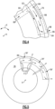
- Figure 3 is a close-up view of a portion of the bearing compartment 60, and illustrates additional detail of the seal assembly 64.
- the seal plate 76 includes a cooling passageway 78 configured to direct a flow of cooling fluid F from a radially inner location 80 to a radially outer location 82.
- the term "radially” refers to the radial direction R, which is normal to the engine central longitudinal axis A.
- the radially inner location 80 is a location radially between the seal plate 76 and the shaft 72, and the radially outer location 82 is radially outside the seal plate 76.
- the fluid F may be an air-oil mixture, such as oil mist.
- the face seal 74 is biased against the seal plate 76 to keep the fluid F within the bearing compartment 60 and to prevent ingress of other potential contaminants.
- the fluid F serves to cool the seal plate 76, which may generate significant heat during operation by virtue of its contact with the face seal 74.
- the seal plate 76 and the face seal 74 contact at a contact area 84.
- the contact area 84 is an area where the fore face seal 74 directly contacts the aft face of the seal plate 76.
- the term "contact area" in this disclosure is not limited to the actual contact area where, at a molecular level, the face seal 74 and the seal plate 76 truly do contact, but instead refers to the apparent contact area.
- the cooling passageway 78 includes a circumferentially-extending section 86 adjacent the contact area 84.
- the circumferentially-extending section 86 is arranged such that fluid F within the cooling passageway 78 absorbs a relatively large amount of heat from the contact area 84.
- the cooling passageway 78 includes an inlet 88 adjacent the radially inner location 80, which leads to an inlet section 90 of the cooling passageway 78.
- the inlet section 90 is inclined relative to the engine central longitudinal axis A and fluidly couples the inlet 88 to circumferentially-extending section 86.
- the inlet section 90 has both a radial and an axial component.
- the inlet section 90 may be provided by a cylindrical bore, in some examples.
- the inlet section 90 in this example, does not direct fluid in a circumferential direction within the seal plate 76.
- the circumferentially-extending section 86 extends circumferentially, in the circumferential direction X, about the engine central longitudinal axis A, from a first circumferential location 92 where the inlet section 90 fluidly couples to the circumferentially-extending section 86 to a second circumferential location 94. At the second circumferential location 94, the circumferentially-extending section 86 is fluidly coupled to an outlet section 96 of the cooling passageway 78.
- the outlet section 96 extends in the radial direction R from the circumferentially-extending section 86 to an outlet 98 of the cooling passageway 78.
- the outlet 98 is provided by a cylindrical bore, in one example, which extends in a direction parallel to the radial direction, and does not have an axial or circumferential component.
- the inlet 88 of the cooling passageway 78 is circumferentially spaced-apart, the circumferential direction X, from the outlet 98. More particularly, the inlet section 90 and the outlet section 96 are fluidly coupled to opposite circumferential sides of the circumferentially-extending section 86, and thus the inlet and outlet sections 90, 96 are circumferentially spaced-apart from one another.
- fluid F enters the inlet 88 and flows through the inlet section 90 toward the circumferentially-extending section 86.
- the fluid F impinges upon an aft surface 100 defining an aft-most boundary of the circumferentially extending section 86.
- the fluid F also turns substantially ninety degrees toward the circumferential direction X, and continues downstream, flowing circumferentially through the circumferentially-extending section 86, absorbing heat from the contact area 84. Adjacent the outlet section 98, the fluid F again turns substantially ninety degrees toward the radial direction R as it exits the circumferentially-extending section 86 and enters the outlet section 96.
- the circumferentially-extending passageway 86 is arranged so that fluid flowing therein absorbs a substantial amount of heat from the contact area 84.
- the circumferentially-extending passageway 86 is substantially rectangular in cross-section, having a height H in the radial direction R which is greater than a width W in the axial direction A.
- the aft surface 100 is relatively close to the contact area 84.
- the aft surface 100 is spaced-apart from the contact area 84 by a distance D in the axial direction A, which in one example is within a range of 0.02 inches (about 0.05 cm) and 0.08 inches (0.2 cm). In a particular example, the distance D is 0.03 inches (about 0.08 cm).
- the circumferentially-extending section 86 is radially aligned with the contact area 84, meaning they are present at the same radial distance from the engine central longitudinal axis A.
- the circumferentially-extending section 86 is arranged such that its height H extends radially inward and outward of the contact area 84. More particularly, the height H extends radially inward and outward of a portion 102 of the face seal 74 that contacts the seal plate 76.
- the portion 102 has a height S, which is less than the height H.
- the contact area 84 also exhibits the height S.
- circumferentially-extending section 86 radially overlaps the entire contact area 84 in Figure 3
- this disclosure extends to arrangements where at least a portion of the circumferentially-extending section 86 is radially aligned with the contact area 84.
- the cooling passageway 78 absorbs a relatively large amount of heat from the contact area 84, which has a number of benefits. Namely, since the fluid F absorbs more heat, the face seal 74 and seal plate 76 may be smaller than prior designs. This reduces material, leading to cost savings and weight reduction. This disclosure also prolongs the effectiveness and the operating life of the seal assembly 64.
- the seal plate 76 includes a plurality of cooling passageways 78' arranged in substantially the same way as the cooling passageway 78 discussed above. Each of the individual cooling passageways 78' is circumferentially spaced-apart from one another, as shown in Figure 5 . With additional cooling passageways 78', the fluid in each of the individual cooling passageways absorbs only a fraction of the heat generated between the face seal 74 and seal plate 76. In one embodiment, the seal plate 76 includes between four and twelve cooling passageways 78'. That said, this disclosure extends to seal plates 76 having one or more cooling passageways 78'.
- the cooling passageway 78 may include flow augmentation features, such as trip strips, bumps, dimples, pedestals, etc. Such features may be formed in the inlet section 90, the outlet section 96, and/or the circumferentially-extending section 86.
- Figure 6 illustrates another aspect of this disclosure. Specifically, Figure 6 is similar to Figure 5 , but illustrates a seal plate 76 having different cooling passageways 78".
- the cooling passageways 78" substantially correspond to the cooling passageways 78, 78', however the cooling passageways 78" are curved and have rounded corners to reduce pressure losses, enhance heat transfer, and distribute heat transfer evenly as the fluid mixture increases in temperature.
- a lower (i.e., radially inner) boundary of the circumferentially-extending section 86 includes a first transition 110 adjacent the first circumferential location 92, and a second transition 112 adjacent the second circumferential location 94.
- the transitions 110, 112 are rounded and smooth.
- the first and second transitions 110, 112 are arranged as 90° ⁇ 15° angles.
- the seal plate 76 can be formed using one of a number of known manufacturing techniques, including lost wax casting or additive manufacturing.
- the cooling passageway 78 could be formed in the seal plate 76 using more traditional manufacturing techniques such as milling and drilling.
- the seal plate 76 could be a multi-piece part.
- the circumferentially extending section 86 could be milled, and the inlet and outlet sections 90, 96 could be drilled, as examples, into a first piece. Then, a second piece could be attached to the first piece, such as by welding or brazing, to enclose the circumferentially-extending section 86. While some example manufacturing techniques have been mentioned herein, this disclosure extends to other manufacturing techniques.
Description
- A gas turbine engine typically includes a fan section, a compressor section, a combustor section, and a turbine section. Air entering the compressor section is compressed and delivered into the combustor section where it is mixed with fuel and ignited to generate a high-speed exhaust gas flow. The high-speed exhaust gas flow expands through the turbine section to drive the compressor and the fan section. The compressor section typically includes low and high pressure compressors, and the turbine section includes low and high pressure turbines.
- A gas turbine engine also includes bearings that support rotatable shafts. The bearings require lubricant. Various seals near the rotating shafts contain oil within bearing compartments, which include bearings and seals. During operation of the engine, non-rotating seal faces contact rotating seal plates to maintain compartment pressures and keep lubricating oil inside the various compartments. Friction between the seals and seal plates generates heat and exposes the seals to relatively high temperatures. In the past, carbon materials have been used to increase seal wear life. In other assemblies, such as in
U.S. Patent Application Publication No. 2013/0078079 , a seal plate is cooled with a flow of cooling fluid, which increases heat transfer away from the seal and reduces seal operating temperature. -
EP 3382240 A1 discloses a gas turbine engine having the features of the preamble of claim 1. -
EP 3282153 A1 discloses a hydrodynamic seal seat cooling feature. -
US 2990202 A discloses a labyrinth face seal plate. - A gas turbine engine according to a first aspect of the present invention is claimed in claim 1.
- Various embodiments of the invention are set out in the dependent claims.
- The embodiments, examples and alternatives of the preceding paragraphs, the claims, or the following description and drawings, including any of their various aspects or respective individual features, may be taken independently or in any combination. Features described in connection with one embodiment are applicable to all embodiments, unless such features are incompatible.
-
-
Figure 1 schematically illustrates a gas turbine engine. -
Figure 2 illustrates a portion of the engine, and in particular illustrates a bearing compartment including a bearing assembly and a seal assembly. -
Figure 3 is a close-up view of the portion of the engine ofFigure 2 , and illustrates additional detail of the seal assembly. -
Figure 4 is a close-up view of a portion of a seal plate from an exterior perspective. -
Figure 5 is a view of the seal plate from an exterior perspective. -
Figure 6 is a view of the seal plate from an exterior perspective. InFigure 6 , the cooling passageways are configured differently than inFigure 5 . -
Figure 1 schematically illustrates agas turbine engine 20. Thegas turbine engine 20 is disclosed herein as a two-spool turbofan that generally incorporates afan section 22, acompressor section 24, a combustor section 26 and aturbine section 28. Thefan section 22 drives air along a bypass flow path B in a bypass duct defined within anacelle 15, and also drives air along a core flow path C for compression and communication into the combustor section 26 then expansion through theturbine section 28. Although depicted as a two-spool turbofan gas turbine engine in the disclosed non-limiting embodiment, it should be understood that the concepts described herein are not limited to use with two-spool turbofans as the teachings may be applied to other types of turbine engines including three-spool architectures. - The
exemplary engine 20 generally includes alow speed spool 30 and ahigh speed spool 32 mounted for rotation about an engine central longitudinal axis A relative to an enginestatic structure 36 viaseveral bearing systems 38. It should be understood thatvarious bearing systems 38 at various locations may alternatively or additionally be provided, and the location ofbearing systems 38 may be varied as appropriate to the application. - The
low speed spool 30 generally includes aninner shaft 40 that interconnects, a first (or low) pressure compressor 44 and a first (or low)pressure turbine 46. Theinner shaft 40 is connected to thefan 42 through a speed change mechanism, which in exemplarygas turbine engine 20 is illustrated as a gearedarchitecture 48 to drive afan 42 at a lower speed than thelow speed spool 30. Thehigh speed spool 32 includes anouter shaft 50 that interconnects a second (or high)pressure compressor 52 and a second (or high)pressure turbine 54. Acombustor 56 is arranged inexemplary gas turbine 20 between thehigh pressure compressor 52 and thehigh pressure turbine 54. Amid-turbine frame 57 of the enginestatic structure 36 may be arranged generally between thehigh pressure turbine 54 and thelow pressure turbine 46. Themid-turbine frame 57 further supports bearingsystems 38 in theturbine section 28. Theinner shaft 40 and theouter shaft 50 are concentric and rotate viabearing systems 38 about the engine central longitudinal axis A which is collinear with their longitudinal axes. - The core airflow is compressed by the low pressure compressor 44 then the
high pressure compressor 52, mixed and burned with fuel in thecombustor 56, then expanded over thehigh pressure turbine 54 andlow pressure turbine 46. Themid-turbine frame 57 includesairfoils 59 which are in the core airflow path C. Theturbines low speed spool 30 andhigh speed spool 32 in response to the expansion. It will be appreciated that each of the positions of thefan section 22,compressor section 24, combustor section 26,turbine section 28, and fandrive gear system 48 may be varied. For example,gear system 48 may be located aft of the low pressure compressor, or aft of the combustor section 26 or even aft ofturbine section 28, andfan 42 may be positioned forward or aft of the location ofgear system 48. - The
engine 20 in one example is a high-bypass geared aircraft engine. In a further example, theengine 20 bypass ratio is greater than about six, with an example embodiment being greater than about ten, the gearedarchitecture 48 is an epicyclic gear train, such as a planetary gear system or other gear system, with a gear reduction ratio of greater than about 2.3 and thelow pressure turbine 46 has a pressure ratio that is greater than about five. In one disclosed embodiment, theengine 20 bypass ratio is greater than about ten, the fan diameter is significantly larger than that of the low pressure compressor 44, and thelow pressure turbine 46 has a pressure ratio that is greater than about five.Low pressure turbine 46 pressure ratio is pressure measured prior to inlet oflow pressure turbine 46 as related to the pressure at the outlet of thelow pressure turbine 46 prior to an exhaust nozzle. The gearedarchitecture 48 may be an epicycle gear train, such as a planetary gear system or other gear system, with a gear reduction ratio of greater than about 2.3:1 and less than about 5:1. It should be understood, however, that the above parameters are only exemplary of one embodiment of a geared architecture engine and that the present invention is applicable to other gas turbine engines including direct drive turbofans, low bypass engines, and multi-stage fan engines. - A significant amount of thrust is provided by the bypass flow B due to the high bypass ratio. The
fan section 22 of theengine 20 is designed for a particular flight condition -- typically cruise at about 0.8 Mach and about 35,000 feet (10,668 meters). The flight condition of 0.8 Mach and 35,000 ft (10,668 meters), with the engine at its best fuel consumption - also known as "bucket cruise Thrust Specific Fuel Consumption ('TSFC')" - is the industry standard parameter of lbm of fuel being burned divided by lbf of thrust the engine produces at that minimum point. "Low fan pressure ratio" is the pressure ratio across the fan blade alone, without a Fan Exit Guide Vane ("FEGV") system. The low fan pressure ratio as disclosed herein according to one non-limiting embodiment is less than about 1.45. "Low corrected fan tip speed" is the actual fan tip speed in ft/sec divided by an industry standard temperature correction of [(Tram °R) / (518.7 °R)]0.5 (where °R = K x 9/5). The "Low corrected fan tip speed" as disclosed herein according to one non-limiting embodiment is less than about 1150 ft / second (350.5 meters/second). -
Figure 2 is a partial cross-sectional view of abearing compartment 60 of theengine 20. Thebearing compartment 60 includes abearing assembly 62 and aseal assembly 64 adjacent thebearing assembly 62. As is known in the art, thebearing assembly 62 includes aninner race 66, anouter race 68, and rolling elements, such as balls, 70 configured to roll therebetween. Thebearing assembly 62 is mounted relative to ashaft 72 of theengine 20. Theshaft 72 serves as a radially inner boundary for thebearing compartment 60. - The
bearing compartment 60 is representative of any bearing compartment within theengine 20. Further, theshaft 72 represents either theinner shaft 40 or theouter shaft 50. This disclosure is not limited to bearing compartments at any particular engine location. Further, this disclosure applies outside the context of bearing compartments. - The
seal assembly 64 includes a face seal 74 aseal plate 76. In this example, theface seal 74 is mounted to a static structure, and therefore does not rotate during operation of theengine 20. Theface seal 74 may be made of a carbon (C) material, however other materials come within the scope of this disclosure. - The
face seal 74 is biased against and in direct contact with theseal plate 76. Theseal plate 76 is configured to rotate about the engine central longitudinal axis A with theshaft 72. The contact area between theface seal 74 and theseal plate 76 generates significant heat during operation of thegas turbine engine 20. An example cooling scheme for theface seal 74 will now be described in detail. -
Figure 3 is a close-up view of a portion of thebearing compartment 60, and illustrates additional detail of theseal assembly 64. As shown inFigure 3 , theseal plate 76 includes a coolingpassageway 78 configured to direct a flow of cooling fluid F from a radiallyinner location 80 to a radially outer location 82. The term "radially" refers to the radial direction R, which is normal to the engine central longitudinal axis A. In one example, the radiallyinner location 80 is a location radially between theseal plate 76 and theshaft 72, and the radially outer location 82 is radially outside theseal plate 76. The fluid F may be an air-oil mixture, such as oil mist. Theface seal 74 is biased against theseal plate 76 to keep the fluid F within thebearing compartment 60 and to prevent ingress of other potential contaminants. - The fluid F serves to cool the
seal plate 76, which may generate significant heat during operation by virtue of its contact with theface seal 74. In particular, inFigure 3 , theseal plate 76 and theface seal 74 contact at acontact area 84. Thecontact area 84 is an area where thefore face seal 74 directly contacts the aft face of theseal plate 76. The term "contact area" in this disclosure is not limited to the actual contact area where, at a molecular level, theface seal 74 and theseal plate 76 truly do contact, but instead refers to the apparent contact area. - As will be explained in more detail below, the cooling
passageway 78 includes a circumferentially-extendingsection 86 adjacent thecontact area 84. The circumferentially-extendingsection 86 is arranged such that fluid F within the coolingpassageway 78 absorbs a relatively large amount of heat from thecontact area 84. - With joint reference to
Figures 3 and4 , the coolingpassageway 78 includes aninlet 88 adjacent the radiallyinner location 80, which leads to aninlet section 90 of the coolingpassageway 78. Theinlet section 90 is inclined relative to the engine central longitudinal axis A and fluidly couples theinlet 88 to circumferentially-extendingsection 86. In particular, in this example, theinlet section 90 has both a radial and an axial component. Theinlet section 90 may be provided by a cylindrical bore, in some examples. Theinlet section 90, in this example, does not direct fluid in a circumferential direction within theseal plate 76. - The circumferentially-extending
section 86 extends circumferentially, in the circumferential direction X, about the engine central longitudinal axis A, from a firstcircumferential location 92 where theinlet section 90 fluidly couples to the circumferentially-extendingsection 86 to a secondcircumferential location 94. At the secondcircumferential location 94, the circumferentially-extendingsection 86 is fluidly coupled to anoutlet section 96 of the coolingpassageway 78. - The
outlet section 96 extends in the radial direction R from the circumferentially-extendingsection 86 to anoutlet 98 of the coolingpassageway 78. Theoutlet 98 is provided by a cylindrical bore, in one example, which extends in a direction parallel to the radial direction, and does not have an axial or circumferential component. - As is perhaps best seen in
Figure 4 , theinlet 88 of the coolingpassageway 78 is circumferentially spaced-apart, the circumferential direction X, from theoutlet 98. More particularly, theinlet section 90 and theoutlet section 96 are fluidly coupled to opposite circumferential sides of the circumferentially-extendingsection 86, and thus the inlet andoutlet sections - During operation of the
gas turbine engine 20, fluid F enters theinlet 88 and flows through theinlet section 90 toward the circumferentially-extendingsection 86. As the fluid F exits theinlet section 90 and enters the circumferentially-extendingsection 86, the fluid F impinges upon anaft surface 100 defining an aft-most boundary of thecircumferentially extending section 86. The fluid F also turns substantially ninety degrees toward the circumferential direction X, and continues downstream, flowing circumferentially through the circumferentially-extendingsection 86, absorbing heat from thecontact area 84. Adjacent theoutlet section 98, the fluid F again turns substantially ninety degrees toward the radial direction R as it exits the circumferentially-extendingsection 86 and enters theoutlet section 96. - The circumferentially-extending
passageway 86 is arranged so that fluid flowing therein absorbs a substantial amount of heat from thecontact area 84. In particular, the circumferentially-extendingpassageway 86 is substantially rectangular in cross-section, having a height H in the radial direction R which is greater than a width W in the axial direction A. Further, theaft surface 100 is relatively close to thecontact area 84. In one example, theaft surface 100 is spaced-apart from thecontact area 84 by a distance D in the axial direction A, which in one example is within a range of 0.02 inches (about 0.05 cm) and 0.08 inches (0.2 cm). In a particular example, the distance D is 0.03 inches (about 0.08 cm). - Further, the circumferentially-extending
section 86 is radially aligned with thecontact area 84, meaning they are present at the same radial distance from the engine central longitudinal axis A. In fact, in this example, the circumferentially-extendingsection 86 is arranged such that its height H extends radially inward and outward of thecontact area 84. More particularly, the height H extends radially inward and outward of aportion 102 of theface seal 74 that contacts theseal plate 76. In particular, in this example, theportion 102 has a height S, which is less than the height H. To this end, thecontact area 84 also exhibits the height S. While the circumferentially-extendingsection 86 radially overlaps theentire contact area 84 inFigure 3 , this disclosure extends to arrangements where at least a portion of the circumferentially-extendingsection 86 is radially aligned with thecontact area 84. - By allowing fluid F to flow circumferentially through the
seal plate 76 and in close proximity to thecontact area 84, while also including the added benefits of impinging the fluid F against theaft surface 100, the coolingpassageway 78 absorbs a relatively large amount of heat from thecontact area 84, which has a number of benefits. Namely, since the fluid F absorbs more heat, theface seal 74 andseal plate 76 may be smaller than prior designs. This reduces material, leading to cost savings and weight reduction. This disclosure also prolongs the effectiveness and the operating life of theseal assembly 64. - In some circumstances, cooling passageways such as those described above cause the fluid F to absorb too much heat from the
contact area 84. In such circumstances, the fluid F could change phase. In order to avoid this, in one aspect of this disclosure, theseal plate 76 includes a plurality of cooling passageways 78' arranged in substantially the same way as the coolingpassageway 78 discussed above. Each of the individual cooling passageways 78' is circumferentially spaced-apart from one another, as shown inFigure 5 . With additional cooling passageways 78', the fluid in each of the individual cooling passageways absorbs only a fraction of the heat generated between theface seal 74 andseal plate 76. In one embodiment, theseal plate 76 includes between four and twelve cooling passageways 78'. That said, this disclosure extends to sealplates 76 having one or more cooling passageways 78'. - In one aspect of this disclosure, the cooling
passageway 78 may include flow augmentation features, such as trip strips, bumps, dimples, pedestals, etc. Such features may be formed in theinlet section 90, theoutlet section 96, and/or the circumferentially-extendingsection 86. -
Figure 6 illustrates another aspect of this disclosure. Specifically,Figure 6 is similar toFigure 5 , but illustrates aseal plate 76 havingdifferent cooling passageways 78". The cooling passageways 78" substantially correspond to the coolingpassageways 78, 78', however the coolingpassageways 78" are curved and have rounded corners to reduce pressure losses, enhance heat transfer, and distribute heat transfer evenly as the fluid mixture increases in temperature. For instance, inFigure 6 , a lower (i.e., radially inner) boundary of the circumferentially-extendingsection 86 includes afirst transition 110 adjacent the firstcircumferential location 92, and a second transition 112 adjacent the secondcircumferential location 94. InFigure 6 , thetransitions 110, 112 are rounded and smooth. InFigure 5 , on the other hand, the first andsecond transitions 110, 112 are arranged as 90° ± 15° angles. - The
seal plate 76 can be formed using one of a number of known manufacturing techniques, including lost wax casting or additive manufacturing. Alternatively, the coolingpassageway 78 could be formed in theseal plate 76 using more traditional manufacturing techniques such as milling and drilling. In that example, theseal plate 76 could be a multi-piece part. Thecircumferentially extending section 86 could be milled, and the inlet andoutlet sections section 86. While some example manufacturing techniques have been mentioned herein, this disclosure extends to other manufacturing techniques. - It should be understood that terms such as "axial" and "radial" are used above with reference to the normal operational attitude of the
engine 20. Further, these terms have been used herein for purposes of explanation, and should not be considered otherwise limiting. Terms such as "generally," "substantially," and "about" are not intended to be boundaryless terms, and should be interpreted consistent with the way one skilled in the art would interpret those terms. Additionally, while many components of theengine 20 are shown in cross-section in the figures, it should be understood that certain of these components extend circumferentially around the engine central longitudinal axis A. - Although the different examples have the specific components shown in the illustrations, embodiments of this disclosure are not limited to those particular combinations. It is possible to use some of the components or features from one of the examples in combination with features or components from another one of the examples. In addition, the various figures accompanying this disclosure are not necessarily to scale, and some features may be exaggerated or minimized to show certain details of a particular component or arrangement.
- One of ordinary skill in this art would understand that the above-described embodiments are exemplary and non-limiting. That is, modifications of this disclosure would come within the scope of the claims. Accordingly, the following claims should be studied to determine their true scope and content.
Claims (13)
- A gas turbine engine (20), comprising:a compressor section (24), a combustor section (26), a turbine section (28), and at least one rotatable shaft (72);a seal assembly (64) including a seal plate (76) mounted for rotation with the rotatable shaft (72) and a face seal (74) in contact with the seal plate (76) at a contact area (84), the seal plate (76) including a cooling passageway (78, 78', 78") having a circumferentially-extending section (86) radially aligned with the contact area (84), wherein the cooling passageway (78, 78', 78") includes:an inlet section (90) between an inlet (88) and the circumferentially-extending section (86); andan outlet section (96) between the circumferentially-extending section (86) and an outlet (98); anda source of cooling fluid (F), wherein:characterised in that:the seal plate (76) is arranged such that the cooling fluid (F) flows through the cooling passageway (78, 78', 78") from the inlet (88) to the outlet (98);the cooling passageway (78, 78', 78") is arranged such that the cooling fluid (F) turns ninety degrees as the cooling fluid (F) exits the inlet section (90) and enters the circumferentially-extending section (86);the cooling passageway (78, 78', 78") is arranged such that the cooling fluid (F) turns ninety degrees as the cooling fluid (F) exits the circumferentially-extending section (86) and enters the outlet section (96); andthe circumferentially-extending section (86) is rectangular in cross-section including a width in an axial direction and a height in the radial direction greater than the width,
the outlet section (96) is radially-extending such that cooling fluid (F) flowing within the outlet section (96) flows in a radial direction. - The gas turbine engine as recited in claim 1, further comprising a bearing assembly (62) mounted relative to the rotatable shaft (72), wherein the seal assembly (64) is adjacent the bearing assembly (62).
- The gas turbine engine as recited in claim 1 or 2, wherein the inlet (88) of the cooling passageway (78, 78', 78") is circumferentially spaced-apart from the outlet (98) of the cooling passageway (78, 78', 78").
- The gas turbine engine as recited in any of claims 1 to 3, wherein the cooling passageway (78, 78', 78") is arranged such that the cooling fluid (F) exiting the inlet section (90) impinges on a wall defining the circumferentially-extending section (86).
- The gas turbine engine as recited in any preceding claim, wherein a thickness of the seal plate (76) between the circumferentially-extending section (86) and the contact area (84) is within a range of 0.02 inches (0.05 cm) and 0.08 inches (0.20 cm).
- The gas turbine engine as recited in claim 5, wherein the thickness of the seal plate (76) between the circumferentially-extending section (86) and the contact area (84) is 0.03 inches (0.08 cm).
- The gas turbine engine as recited in any preceding claim, wherein the face seal (74) is made of a carbon material.
- The gas turbine engine as recited in any preceding claim, wherein the circumferentially-extending section (86) radially overlaps the entire contact area (84).
- The gas turbine engine as recited in any preceding claim, wherein:the cooling passageway (78, 78', 78") is one of a plurality of similar cooling passageways (78, 78', 78") formed in the seal plate (76), andeach of the plurality of cooling passageways (78, 78', 78") is circumferentially spaced-apart from one another.
- The gas turbine engine as recited in any preceding claim, wherein the outlet section (96) is provided by a cylindrical bore which does not have an axial or circumferential component.
- The gas turbine engine as recited in any preceding claim, wherein the inlet section (90) has both a radial and an axial component such that the inlet section (90) is inclined relative to an engine central longitudinal axis A, and the inlet section (90) does not direct fluid in a circumferential direction within the seal plate (76).
- The gas turbine engine as recited in any preceding claim, wherein the circumferentially-extending section (86) includes a first rounded corner (110) adjacent the inlet section (90) configured to turn the cooling fluid (F) exiting the inlet section (90), and a second rounded corner (112) adjacent the outlet section (96) configured to turn the cooling fluid (F) exiting the circumferentially-extending section (86).
- The gas turbine engine as recited in any preceding claim, wherein the outlet section (96) extends radially from a radially-outer section (94) of the circumferentially-extending section (86).
Applications Claiming Priority (1)
| Application Number | Priority Date | Filing Date | Title |
|---|---|---|---|
| US16/285,820 US10975723B2 (en) | 2019-02-26 | 2019-02-26 | Gas turbine engine including seal plate providing increased cooling adjacent contact area |
Publications (2)
| Publication Number | Publication Date |
|---|---|
| EP3702586A1 EP3702586A1 (en) | 2020-09-02 |
| EP3702586B1 true EP3702586B1 (en) | 2024-03-27 |
Family
ID=69740243
Family Applications (1)
| Application Number | Title | Priority Date | Filing Date |
|---|---|---|---|
| EP20159549.3A Active EP3702586B1 (en) | 2019-02-26 | 2020-02-26 | Gas turbine engine including seal plate providing increased cooling adjacent contact area |
Country Status (2)
| Country | Link |
|---|---|
| US (1) | US10975723B2 (en) |
| EP (1) | EP3702586B1 (en) |
Families Citing this family (8)
| Publication number | Priority date | Publication date | Assignee | Title |
|---|---|---|---|---|
| US11753964B2 (en) | 2018-10-29 | 2023-09-12 | Rtx Corporation | Oil-cooled carbon seal |
| GB2580037B (en) * | 2018-12-19 | 2021-04-28 | Gkn Aerospace Sweden Ab | Anti-coking |
| US11131388B2 (en) * | 2019-06-21 | 2021-09-28 | Raytheon Technologies Corporation | Seal assembly seal land with a gas flow passage |
| US11193389B2 (en) * | 2019-10-18 | 2021-12-07 | Raytheon Technologies Corporation | Fluid cooled seal land for rotational equipment seal assembly |
| US11441448B2 (en) * | 2020-02-13 | 2022-09-13 | Raytheon Technologies Corporation | Impingement cooled rotating seal |
| US11821322B2 (en) | 2020-11-13 | 2023-11-21 | Eaton Intelligent Power Limited | Additive manufactured seal rotor; and method |
| EP4036376B1 (en) * | 2020-12-15 | 2023-11-15 | RTX Corporation | Oil-cooled carbon seal |
| US11608751B2 (en) * | 2021-03-19 | 2023-03-21 | Raytheon Technologies Corporation | Self-guiding carbon seal system |
Family Cites Families (35)
| Publication number | Priority date | Publication date | Assignee | Title |
|---|---|---|---|---|
| US2857182A (en) * | 1955-05-31 | 1958-10-21 | Gen Motors Corp | Shaft seal |
| US2990202A (en) * | 1958-09-18 | 1961-06-27 | United Aircraft Corp | Labyrinth face seal plate |
| US3804424A (en) * | 1972-04-24 | 1974-04-16 | Crane Packing Co | Gap seal with thermal and pressure distortion compensation |
| US3915521A (en) | 1974-09-30 | 1975-10-28 | United Technologies Corp | Lubricated radial bearing assembly |
| US4406459A (en) * | 1982-06-18 | 1983-09-27 | United Technologies Corporation | Oil weepage return for carbon seal plates |
| US4406460A (en) * | 1982-11-01 | 1983-09-27 | United Technologies Corporation | Anti-weepage valve for rotating seals |
| US4406466A (en) * | 1982-11-29 | 1983-09-27 | Elliott Turbomachinery Co., Inc. | Gas lift bearing and oil seal |
| US4928978A (en) * | 1988-04-07 | 1990-05-29 | United Technologies Corporation | Rotating shaft seal |
| EP0685048B1 (en) * | 1992-08-11 | 2000-01-19 | United Technologies Corporation | Seal assembly for a rotary machine |
| US5636848A (en) * | 1995-02-22 | 1997-06-10 | Alliedsignal Inc. | Oil seal for a high speed rotating shaft |
| US5622438A (en) * | 1995-07-12 | 1997-04-22 | United Technologies Corporation | Fire resistant bearing compartment cover |
| US5639096A (en) * | 1996-07-11 | 1997-06-17 | Alliedsignal Inc. | Oil film cooled face seal |
| US6454268B1 (en) * | 2001-02-09 | 2002-09-24 | Eagle Industry Co., Ltd. | Shaft seal device |
| US6719296B2 (en) * | 2002-07-12 | 2004-04-13 | General Electric Company | Seal for a rotating member |
| US7984911B2 (en) * | 2008-01-17 | 2011-07-26 | United Technologies Corporation | Face seal for gas turbine engine |
| US7946590B2 (en) | 2008-01-17 | 2011-05-24 | United Technologies Corporation | Face seal for gas turbine engine |
| US8777229B2 (en) | 2010-03-26 | 2014-07-15 | United Technologies Corporation | Liftoff carbon seal |
| US8845282B2 (en) * | 2011-09-28 | 2014-09-30 | United Technologies Corporation | Seal plate with cooling passage |
| US20140140824A1 (en) * | 2012-10-26 | 2014-05-22 | United Technologies Corporation | Oil system bearing compartment architecture for gas turbine engine |
| US20140119887A1 (en) * | 2012-11-01 | 2014-05-01 | United Technologies Corporation | Fluid-cooled seal arrangement for a gas turbine engine |
| US9309783B2 (en) | 2013-01-10 | 2016-04-12 | General Electric Company | Seal assembly for turbine system |
| WO2014130662A1 (en) * | 2013-02-20 | 2014-08-28 | United Technologies Corporation | Rolling element bearing configured with a gutter and one or more fluid passages |
| WO2014133952A1 (en) * | 2013-02-27 | 2014-09-04 | United Technologies Corporation | Cooled seal assembly for arranging between a stator and a rotor |
| WO2014152167A1 (en) * | 2013-03-14 | 2014-09-25 | United Technologies Corporation | Rolling element bearing configured with a channel and one or more fluid passages |
| US9631508B2 (en) | 2013-06-13 | 2017-04-25 | Pratt & Whitney Canada Corp. | Internally cooled seal runner |
| WO2015069348A1 (en) * | 2013-11-06 | 2015-05-14 | United Technologies Corporation | Axial scoop seal plate |
| US9719373B2 (en) * | 2013-12-03 | 2017-08-01 | United Technologies Corporation | Slotted distribution sleeve for a seal plate |
| US10287981B2 (en) | 2014-03-31 | 2019-05-14 | United Technologies Corporation | Seal assembly with cooling feature |
| US9951872B2 (en) | 2015-06-19 | 2018-04-24 | Caterpillar Inc. | Mechanical face seal |
| US9909438B2 (en) * | 2016-04-12 | 2018-03-06 | United Technologies Corporation | Hydrodynamic carbon face seal pressure booster |
| US10274085B2 (en) * | 2016-06-28 | 2019-04-30 | Flowserve Management Company | Dry running end face mechanical seal |
| EP3495638B1 (en) * | 2016-08-02 | 2021-01-06 | Eagle Industry Co., Ltd. | Sealing device |
| US20180045316A1 (en) * | 2016-08-09 | 2018-02-15 | United Technologies Corporation | Hydrodynamic seal seat cooling features |
| US10422245B2 (en) | 2017-03-28 | 2019-09-24 | United Technologies Corporation | Seal element with internal lubricant plenum for rotational equipment |
| US11236636B2 (en) | 2018-10-29 | 2022-02-01 | Raytheon Technologies Corporation | Oil-cooled carbon seal |
-
2019
- 2019-02-26 US US16/285,820 patent/US10975723B2/en active Active
-
2020
- 2020-02-26 EP EP20159549.3A patent/EP3702586B1/en active Active
Also Published As
| Publication number | Publication date |
|---|---|
| EP3702586A1 (en) | 2020-09-02 |
| US10975723B2 (en) | 2021-04-13 |
| US20200271013A1 (en) | 2020-08-27 |
Similar Documents
| Publication | Publication Date | Title |
|---|---|---|
| EP3702586B1 (en) | Gas turbine engine including seal plate providing increased cooling adjacent contact area | |
| US10352195B2 (en) | Non-contacting seals for geared gas turbine engine bearing compartments | |
| US10287981B2 (en) | Seal assembly with cooling feature | |
| EP3246523B1 (en) | Cooled blade outer air seal | |
| EP3708794B1 (en) | Dual radial scoop oil delivery system | |
| EP3960992A2 (en) | Seal runner flow damper | |
| EP3318722B1 (en) | Seal assembly for a rotatable component | |
| EP3293360A1 (en) | Seal system with primary and secondary seal arrangement | |
| US11725694B2 (en) | Seal runner with deflector and catcher for gas turbine engine | |
| EP4012162B1 (en) | Rotating sleeve controlling clearance of seal assembly of gas turbine engine | |
| US10443443B2 (en) | Non-contacting seals for geared gas turbine engine bearing compartments | |
| US11248492B2 (en) | Seal assembly for a gas turbine engine | |
| US10774684B2 (en) | Gas turbine engine seal assemblies | |
| US10526917B2 (en) | Platform lip impingement features | |
| US11306656B2 (en) | Oil drainback arrangement for gas turbine engine | |
| EP3783203B1 (en) | Gas turbine engine component comprising a radial seal arrangement with axially elongated oil cooled runner | |
| EP3712471B1 (en) | Two-piece seat for contacting seal | |
| US11773738B2 (en) | Radial lift seal | |
| US11293307B2 (en) | Partial arc gutter for gas turbine engine |
Legal Events
| Date | Code | Title | Description |
|---|---|---|---|
| PUAI | Public reference made under article 153(3) epc to a published international application that has entered the european phase |
Free format text: ORIGINAL CODE: 0009012 |
|
| STAA | Information on the status of an ep patent application or granted ep patent |
Free format text: STATUS: THE APPLICATION HAS BEEN PUBLISHED |
|
| AK | Designated contracting states |
Kind code of ref document: A1 Designated state(s): AL AT BE BG CH CY CZ DE DK EE ES FI FR GB GR HR HU IE IS IT LI LT LU LV MC MK MT NL NO PL PT RO RS SE SI SK SM TR |
|
| AX | Request for extension of the european patent |
Extension state: BA ME |
|
| STAA | Information on the status of an ep patent application or granted ep patent |
Free format text: STATUS: REQUEST FOR EXAMINATION WAS MADE |
|
| RAP1 | Party data changed (applicant data changed or rights of an application transferred) |
Owner name: RAYTHEON TECHNOLOGIES CORPORATION |
|
| 17P | Request for examination filed |
Effective date: 20210302 |
|
| RBV | Designated contracting states (corrected) |
Designated state(s): AL AT BE BG CH CY CZ DE DK EE ES FI FR GB GR HR HU IE IS IT LI LT LU LV MC MK MT NL NO PL PT RO RS SE SI SK SM TR |
|
| STAA | Information on the status of an ep patent application or granted ep patent |
Free format text: STATUS: EXAMINATION IS IN PROGRESS |
|
| 17Q | First examination report despatched |
Effective date: 20220407 |
|
| GRAP | Despatch of communication of intention to grant a patent |
Free format text: ORIGINAL CODE: EPIDOSNIGR1 |
|
| STAA | Information on the status of an ep patent application or granted ep patent |
Free format text: STATUS: GRANT OF PATENT IS INTENDED |
|
| INTG | Intention to grant announced |
Effective date: 20231009 |
|
| RAP3 | Party data changed (applicant data changed or rights of an application transferred) |
Owner name: RTX CORPORATION |
|
| GRAS | Grant fee paid |
Free format text: ORIGINAL CODE: EPIDOSNIGR3 |
|
| GRAA | (expected) grant |
Free format text: ORIGINAL CODE: 0009210 |
|
| STAA | Information on the status of an ep patent application or granted ep patent |
Free format text: STATUS: THE PATENT HAS BEEN GRANTED |
|
| AK | Designated contracting states |
Kind code of ref document: B1 Designated state(s): AL AT BE BG CH CY CZ DE DK EE ES FI FR GB GR HR HU IE IS IT LI LT LU LV MC MK MT NL NO PL PT RO RS SE SI SK SM TR |
|
| REG | Reference to a national code |
Ref country code: GB Ref legal event code: FG4D |
|
| REG | Reference to a national code |
Ref country code: CH Ref legal event code: EP |
|
| REG | Reference to a national code |
Ref country code: DE Ref legal event code: R096 Ref document number: 602020027761 Country of ref document: DE |