US6554237B1 - Self aligning curtain rod bracket - Google Patents
Self aligning curtain rod bracket Download PDFInfo
- Publication number
- US6554237B1 US6554237B1 US09/565,789 US56578900A US6554237B1 US 6554237 B1 US6554237 B1 US 6554237B1 US 56578900 A US56578900 A US 56578900A US 6554237 B1 US6554237 B1 US 6554237B1
- Authority
- US
- United States
- Prior art keywords
- bracket
- mounting plate
- front mounting
- molding
- corner
- Prior art date
- Legal status (The legal status is an assumption and is not a legal conclusion. Google has not performed a legal analysis and makes no representation as to the accuracy of the status listed.)
- Expired - Fee Related
Links
- 238000000465 moulding Methods 0.000 claims abstract description 71
- 238000004026 adhesive bonding Methods 0.000 claims description 3
- 230000000149 penetrating effect Effects 0.000 claims description 2
- 229920000915 polyvinyl chloride Polymers 0.000 claims description 2
- 239000004800 polyvinyl chloride Substances 0.000 claims description 2
- 238000009428 plumbing Methods 0.000 claims 1
- 239000000853 adhesive Substances 0.000 abstract description 8
- 230000001070 adhesive effect Effects 0.000 abstract description 8
- 239000000463 material Substances 0.000 description 4
- 238000005452 bending Methods 0.000 description 3
- 230000000295 complement effect Effects 0.000 description 2
- 239000004033 plastic Substances 0.000 description 2
- 229920003023 plastic Polymers 0.000 description 2
- 238000011282 treatment Methods 0.000 description 2
- 229910001369 Brass Inorganic materials 0.000 description 1
- 241000276426 Poecilia Species 0.000 description 1
- 229910052782 aluminium Inorganic materials 0.000 description 1
- XAGFODPZIPBFFR-UHFFFAOYSA-N aluminium Chemical compound [Al] XAGFODPZIPBFFR-UHFFFAOYSA-N 0.000 description 1
- 239000007767 bonding agent Substances 0.000 description 1
- 239000010951 brass Substances 0.000 description 1
- 230000006835 compression Effects 0.000 description 1
- 238000007906 compression Methods 0.000 description 1
- 238000005336 cracking Methods 0.000 description 1
- 238000006073 displacement reaction Methods 0.000 description 1
- 229920005669 high impact polystyrene Polymers 0.000 description 1
- 239000004797 high-impact polystyrene Substances 0.000 description 1
- 238000002347 injection Methods 0.000 description 1
- 239000007924 injection Substances 0.000 description 1
- 229910052751 metal Inorganic materials 0.000 description 1
- 239000002184 metal Substances 0.000 description 1
- 239000012778 molding material Substances 0.000 description 1
- 238000010422 painting Methods 0.000 description 1
- 239000011505 plaster Substances 0.000 description 1
- 230000002250 progressing effect Effects 0.000 description 1
- 230000008439 repair process Effects 0.000 description 1
- 239000012858 resilient material Substances 0.000 description 1
- 230000000284 resting effect Effects 0.000 description 1
- 239000002023 wood Substances 0.000 description 1
Images


Classifications
-
- A—HUMAN NECESSITIES
- A47—FURNITURE; DOMESTIC ARTICLES OR APPLIANCES; COFFEE MILLS; SPICE MILLS; SUCTION CLEANERS IN GENERAL
- A47H—FURNISHINGS FOR WINDOWS OR DOORS
- A47H1/00—Curtain suspension devices
- A47H1/10—Means for mounting curtain rods or rails
- A47H1/14—Brackets for supporting rods or rails
- A47H1/142—Brackets for supporting rods or rails for supporting rods
Definitions
- This invention relates to mounting apparatus for attachment to wall moldings that frame an opening, to support and correctly position rod elements for carrying curtains, valences and similar window treatments.
- a bracket having a positioning flange extending into the opening is attachable to the front and inner surfaces of a framed opening, via resilient adhesive pads, thereby preventing damage.
- the pads have a thickness permitting the bracket to be adjusted in mutually perpendicular directions such that the bracket can accommodate the slope and contour of the molding or support frame, positioning the bracket and therefore the curtain rod correctly relative to the inside corner of the frame.
- the window or door is defined by a frame which may include a bordering molding mounted to the frame around the opening.
- the typical molding is tapered in thickness and protrudes from the wall surface to a greater extend proceeding away from the edge of the opening.
- Brackets for mounting rods for depending curtains, valences and the like commonly have a flat base plate with openings to receive one or more nails, screws or the like, which are driven or threaded into the molding to fix the bracket in position on opposite sides of the door or window frame.
- One or more hooked arms extends forward and typically upward from the base plate, and engages in the hollow curtain rod via a hole spaced from the end of the rod near an L-shaped bend at each end of the rod.
- the base plate is integral with a side mounting plate that extends rearwardly from the flat base plate to wrap around the outer corner of the molding surrounding the frame.
- the side mounting plate can also have one or more openings for receiving fasteners such as nails or screws.
- Brackets with side mounting plates are useful in that the side mounting plates inherently position the curtain rod hooks at a given position relative to the outer edge of the molding. However, this feature is not available for framed openings that do not have a protruding molding defining such outer edge.
- a problem with certain curtain rod brackets having a side mounting plate is that the bracket can be conspicuously visible and can interfere with the aesthetic appeal of the window treatment.
- An additional problem with this type of bracket is that the relatively permanent nails or screws used as fasteners produce holes in the molding and the brackets are often painted over. When the brackets or their positions are changed, nail or screw holes in the molding or frame, and any unevenness in the painted surface, require repairs.
- Brackets for mounting curtain rods are disclosed in U.S. Pat. Nos. 5,577,700—Williams and 5,230,494—Adams.
- Williams discloses a bracket which has a sideways extending flange with apertures for receiving nails and screws. The bracket is fixed in place by nailing or screwing the flange to the wall adjacent the molding. Williams avoids damage to the molding at the expense of the wall which is often comprised of more fragile materials such as plaster or dry wall. Attaching screws or nails into dry wall often requires attention to cracking, or expandable screw fittings such as mollies or toggle screws.
- Adams discloses a bracket which is mounted on an array of suction cups. The suction cups are attached directly to the window. In addition to creating an aesthetically unappealing situation, this type of product cannot be used with windows that open outwardly on a hinge axis.
- mounting brackets are not well suited to being mounted on the surfaces of contoured moldings.
- the bracket When a molding around a window or door is substantially rectilinear and has a flat facing surface, the bracket orients the rod hooks directly forwardly when resting flush against the molding.
- most moldings are angled such that they are thinner at the edge of the opening and thicker progressing outwardly. Moldings also are often rounded or otherwise contoured.
- a contoured or sloped molding at best causes the bracket to rest awkwardly on the molding (for example against a limited width of molding material) and may misalign the rod hooks such that it is difficult to place and remove the rod.
- Brackets can be shaped to complement the contour of moldings. However, the bracket must be customized to the molding and may be impractical for uncommon molding patterns.
- curtain rod bracket which when mounted is substantially concealed, avoids damage to the wall or frame and particularly to the wall adjacent to an opening framed by a molding, and is adjustable as well as self-positioning to accommodate the contour of the molding.
- It is an object of the invention provide a bracket for supporting curtain rods which is substantially concealed when mounted and supporting a curtain.
- a bracket comprised of a front mounting plate and a side mounting flange which extends rearwardly from the front mounting plate at substantially a right angle.
- At least one rod support arm is located in the upper outside corner of the front mounting plate and extends forwardly in a plane parallel to the side mounting flange.
- the support arm has a horizontal bearing surface for supporting the weight of a curtain rod that is hollow at an end facing the bracket.
- a knob protrudes upwardly from the bearing surface and mates with a corresponding aperture in the curtain rod such that the arm and knob constrain the curtain rod from moving in a horizontal direction or from rotating downwardly when mounted.
- the knob can alternatively be formed as the end of an upwardly curved hook shaped arm extending outwardly from the front mounting plate.
- Adhesive bonding pads are attached to the surfaces of the side flange and front mounting plate facing the edges of the opening, the pads comprising relatively thick resilient material with adhesive on both sides for securing the curtain rod mounting device to the window frame.
- the adhesive strip can be provided in different or tapering thicknesses.
- the adhesive strip is compressible to compensate for ridges encountered in contoured molding and/or to accommodate variations in the surface configuration or orientation of the edges of the opening.
- the bracket can comprise a flexible or malleable material which allows the front mounting plate and the side mounting flange to be bent relative to each other to match the slope and contour of the molding.
- the top edges of the side mounting flanges for a bracket on each lateral side of the opening is abutted into the respective upper corner of the framed opening as the bracket is mounted.
- the bracket is simultaneously leveled and affixed to the inside wall of the opening and to the outer surface (e.g., to the face of the molding surrounding the opening). This registers both brackets to the upper edge of the opening and positions the rod engaging hooks at an equal height and distance from the edge of the opening.
- two brackets are mounted to the molding in opposite upper corners of the door or window frame.
- the front mounting plate is juxtaposed to the molding of the door or window so that the side mounting flange extends along the inner part of the door frame perpendicular to the plane of the window.
- the slotted ends of a curtain rod are then mated with the support arms of the bracket.
- the registered placement of the support arms in the upper outer corner of the front mounting plates causes the curtain rod to extend across the top of the opening and parallel to its upper edge.
- the support arms are preferably placed at the extreme outer edge of the mounting plate, and accordingly when curtains are placed on the rod, the bracket is concealed from view.
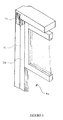
- FIG. 1 is a front perspective view of the mounting bracket embodying the invention
- FIG. 2 is a side elevational view of a support arm of the mounting bracket of FIG. 1;
- FIG. 3 is a front perspective view of a conventional window frame without molding, having an opposite-hand embodiment of the mounting bracket of FIG. 1 mounted thereto;
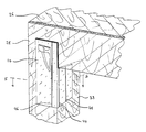
- FIG. 4 is a front perspective view of a corner of a conventional window frame with molding, having an opposite-hand embodiment of the mounting bracket of FIG. 1 mounted thereto;
- FIG. 5 is a sectional view taken along line 5 — 5 of FIG. 4;
- FIG. 5A is a sectional view similar to FIG. 5, showing the mounting bracket mounted to a slightly contoured molding
- FIG. 5B is a sectional view similar to FIG. 5, showing the mounting bracket mounted to a contoured molding
- FIG. 6 is a front perspective view showing an alternative embodiment of the mounting bracket.
- FIG. 7 is a side elevational view of a support arm of the mounting bracket of FIG. 6 .
- FIG. 1 shows the curtain rod mounting bracket 10 according to the invention.
- the mounting bracket 10 can be constructed from a flexible material such as polyvinyl chloride, high impact polystyrene or another type of durable plastic.
- the bracket can be made of a malleable metal such as aluminum or brass.
- Bracket 10 also may be constructed from other materials such as wood.
- bracket 10 can be a single piece injection molded part integrally formed with a front mounting plate 14 for attachment to the facing wall surface adjacent to a window or similar framed opening, a side mounting flange 12 perpendicular thereto for extending into the opening and attaching to an inner side wall, and at a pair of outwardly extending laterally spaced support arms 16 for receiving the end of a curtain rod or the like.
- the side mounting flange 12 extends rearwardly from the outer edge 22 of front mounting plate 14 over only a lower part of the height of plate 14 .
- Support arms 16 extend outwardly from the upper outer corner of front mounting plate 14 such that the curtain rod is placed at the extreme edge of the bracket.
- support arms 16 each have a horizontal bearing surface 17 which supports the weight of curtain rods.
- knobs 18 Protruding upwardly from bearing surfaces 17 are knobs 18 which mate with a corresponding aperture in the hollow curtain rod and prevents the curtain rod from moving in a horizontal direction or rotating downwardly due to cantilevered weight carried by the curtain rod, i.e., the weight of the curtain and any downward force applied to the curtain.
- FIG. 6 An alternative configuration is shown in FIG. 6, wherein a pair of curved hooks 116 extend outwardly from the front mounting plate 114 to form the arms.
- the curved hooks 116 are particularly adapted to receive a tubular curtain rod.
- Support arms 16 and hooks 116 preferably are integral with brackets 10 and 100 respectively.
- hooks 116 and arms 16 can be provided as a separately attached part affixed to front mounting plates 14 , 114 by adhesive or by means of a mechanical fastener such as a screw, rivet or the like.
- front mounting plates 14 , 114 and side mounting flanges 12 , 112 have rear surfaces 34 , 134 and 35 , 135 respectively which have attachment strips 36 , 136 mounted thereto.
- Attachment strip 36 , 136 comprises a relatively thick compressible pad having an adhesive bonding agent on both sides. Strips 36 , 136 adhere to the rear surfaces 34 , 134 and 35 , 135 of brackets 10 , 100 and to the molding and inside wall of a door or window frame.
- the compressible pad allows the brackets 10 , 100 to be better positioned on unevenly contoured molding surfaces and door frames, and accommodates edges that are not precisely plumb, up to the compressible thickness of the pads.
- the pads can be approximately ⁇ fraction (3/16) ⁇ inch (5 mm) thick at rest, and readily compressible to ⁇ fraction (1/16) ⁇ inch (1.6 mm) when mounted.
- the adhesive pads are placed on mutually perpendicular surfaces, either of the pads will remain compressed when mounted because resilient forces normal to the surface, produced by compression of that pad, are resisted substantially along the plane of attachment of the other pad.
- FIG. 3 illustrates a typical window frame structure without molding, in which a frame 26 is disposed in a wall and defines an opening 40 .
- the framed opening is typically occupied by a window or door, but could also be a different type such as an alcove, a framed painting, etc.
- FIG. 4 shows a corner of a conventional window frame with molding, wherein the decorative molding 28 is attached to the face of the frame 26 adjacent the inner face or periphery 38 of frame 26 .
- Decorative molding 28 can be flat and square, but typically is tapered for greater thickness proceeding outwardly, and can be decoratively contoured.
- FIGS. 4 and 5 show frame 26 having a flat molding 28 and FIG.
- FIG. 5A shows a slightly sloped contoured molding 28 A along the door frames 26 , 26 A adjacent the inner periphery 38 , 38 A.
- attachment strip 36 fastens bracket 10 to the molding 28 , 28 A and comprises compressible padding which is coated with an adhesive on two sides.
- the compressible padding of strip 36 allows for compensation in the elevational differences in the ridges of the contoured molding 28 A.
- the attachment strip 36 is compressed along the outside of molding 28 A and remains fully expanded along the inside of molding 28 A. This keeps the rear surface 34 of front mounting plate 14 positioned against the contoured molding 28 A.
- the rear surface 34 can be contoured to complement the molding.
- the side mounting flange 12 can be bent relative to the front mounting plate 14 to better match the slope of the molding.
- the attachment strip 36 lessens the amount of bending which must occur in order to match the slope of the molding 28 B and also conforms to steps and irregularities in the surface.
- the front mounting plate must be bent to ensure that the support arms 16 are properly oriented in a direction perpendicular to door frame 26 .
- the mounting bracket 10 includes creases 44 , 48 and 46 which allow for bending of the side mounting flange 12 and the front mounting plate 14 , respectively.
- brackets 10 are aligned in the upper corners of frame 26 so that the side mounting flange 12 is flush with the inner face 38 of frame 26 and the rear of front mounting plate 14 is flush with the molding, with the top edge of side mounting flange abutted against the top inside of the opening and the bracket set to plumb.
- bracket 10 is attached to flat molding 28 , it is generally only necessary to align the rear surface 34 and press upon the front of bracket 10 which will bond the attachment strips 36 to the molding 28 and the inner face 38 .
- bracket 10 may need to be adjusted depending upon the grade of the slope.
- the compressibly padded attachment strips 36 will compensate for elevational differences in the ridges of the contoured molding.
- the bracket 10 is adjusted to match the grade of the molding by bending side mounting flange 12 relative to front mounting plate 14 along crease 44 . Once the grade is matched, the front face of the bracket is pressed and attachment strip 36 will engage molding 30 . If necessary, the front mounting plate 14 is then bent along crease 46 to align support arms 16 in a direction perpendicular to door frame 26 .
- a curtain rod is fitted with a curtain and placed on brackets 10 , namely on one of the support arms 16 , two being shown for mounting inner and outer curtain rods and curtains.
- the orientation of a curtain rod relative to bracket 10 is such that a rod extends parallel to the top edge of the opening across the tops of brackets 10 and to their extreme outer edges.
- Side mounting flange 12 is attached to the inner periphery 38 of the window frame, 26 .
Landscapes
- Securing Of Glass Panes Or The Like (AREA)
Abstract
A curtain rod mounting bracket is affixed adhesively via a front mounting plate and a side mounting flange to be abutted against the upper inside corner of a window or other framed opening. The front mounting plate extends outwardly from the opening and the side mounting flange extends partway along the height of the front plate and extends rearwardly generally perpendicular to the front plate. One or more curtain rod support hooks are placed at the upper outside edge of the front plate. Relatively thick double sided adhesive strips are attached to the window frame side of the side flange and front mounting plate, securing the bracket to the window frame without damage, and allowing for alignment correction due to an imperfectly squared window frame and/or non-rectilinear moldings.
Description
1. Field of the Invention
This invention relates to mounting apparatus for attachment to wall moldings that frame an opening, to support and correctly position rod elements for carrying curtains, valences and similar window treatments. A bracket having a positioning flange extending into the opening is attachable to the front and inner surfaces of a framed opening, via resilient adhesive pads, thereby preventing damage. The pads have a thickness permitting the bracket to be adjusted in mutually perpendicular directions such that the bracket can accommodate the slope and contour of the molding or support frame, positioning the bracket and therefore the curtain rod correctly relative to the inside corner of the frame.
2. Prior Art
It is often desirable to cover windows, doors and similar framed openings with is curtains or blinds of various types. The window or door is defined by a frame which may include a bordering molding mounted to the frame around the opening. The typical molding is tapered in thickness and protrudes from the wall surface to a greater extend proceeding away from the edge of the opening.
It is customary to attach fixtures on the lateral sides of the opening, for example at the top, for holding the ends of a curtain rod to support curtains that depend across the opening. Venetian blinds are similarly mounted, typically by box-like brackets. Brackets for mounting rods for depending curtains, valences and the like commonly have a flat base plate with openings to receive one or more nails, screws or the like, which are driven or threaded into the molding to fix the bracket in position on opposite sides of the door or window frame. One or more hooked arms extends forward and typically upward from the base plate, and engages in the hollow curtain rod via a hole spaced from the end of the rod near an L-shaped bend at each end of the rod.
According to one type of bracket, the base plate is integral with a side mounting plate that extends rearwardly from the flat base plate to wrap around the outer corner of the molding surrounding the frame. The side mounting plate can also have one or more openings for receiving fasteners such as nails or screws. Brackets with side mounting plates are useful in that the side mounting plates inherently position the curtain rod hooks at a given position relative to the outer edge of the molding. However, this feature is not available for framed openings that do not have a protruding molding defining such outer edge.
A problem with certain curtain rod brackets having a side mounting plate is that the bracket can be conspicuously visible and can interfere with the aesthetic appeal of the window treatment. An additional problem with this type of bracket is that the relatively permanent nails or screws used as fasteners produce holes in the molding and the brackets are often painted over. When the brackets or their positions are changed, nail or screw holes in the molding or frame, and any unevenness in the painted surface, require repairs.
An attempt to provide an improved support bracket is disclosed in U.S. Pat. No. 4,283,034—Sheehan, which discloses a bracket having a rearwardly extending flange which extends over the upper and outer edge of the molding. The flange has tangs which are driven into the top of the molding. Sheehan avoids damage to the front of the molding but requires that the bracket be hung by penetrating the molding from above. The tangs have a wider surface area than a screw or nail and create a larger hole. The bracket is fastened to the molding in a manner which bears vertical force but can only prevent downward and horizontal displacement of the bracket. Upward vertical force can unseat the bracket from the molding.
Further examples of brackets for mounting curtain rods are disclosed in U.S. Pat. Nos. 5,577,700—Williams and 5,230,494—Adams. Williams discloses a bracket which has a sideways extending flange with apertures for receiving nails and screws. The bracket is fixed in place by nailing or screwing the flange to the wall adjacent the molding. Williams avoids damage to the molding at the expense of the wall which is often comprised of more fragile materials such as plaster or dry wall. Attaching screws or nails into dry wall often requires attention to cracking, or expandable screw fittings such as mollies or toggle screws. Adams discloses a bracket which is mounted on an array of suction cups. The suction cups are attached directly to the window. In addition to creating an aesthetically unappealing situation, this type of product cannot be used with windows that open outwardly on a hinge axis.
In general, mounting brackets are not well suited to being mounted on the surfaces of contoured moldings. When a molding around a window or door is substantially rectilinear and has a flat facing surface, the bracket orients the rod hooks directly forwardly when resting flush against the molding. However, most moldings are angled such that they are thinner at the edge of the opening and thicker progressing outwardly. Moldings also are often rounded or otherwise contoured. A contoured or sloped molding at best causes the bracket to rest awkwardly on the molding (for example against a limited width of molding material) and may misalign the rod hooks such that it is difficult to place and remove the rod. Brackets can be shaped to complement the contour of moldings. However, the bracket must be customized to the molding and may be impractical for uncommon molding patterns.
It would be desirable to provide a curtain rod bracket which when mounted is substantially concealed, avoids damage to the wall or frame and particularly to the wall adjacent to an opening framed by a molding, and is adjustable as well as self-positioning to accommodate the contour of the molding.
It is an object of the invention provide a bracket for supporting curtain rods which is substantially concealed when mounted and supporting a curtain.
It is also an object of the invention to provide a bracket for supporting curtain rods and hangers which is adjustable to conform to sloped or otherwise contoured moldings.
It is a further object of the invention to provide a bracket for supporting curtain rods and hangers which does not damage the frame or molding of a door or window.
It is another object of the invention to provide a bracket as described that additionally has self-positioning structures that abut inside edges and surfaces of a framed opening.
These and other objects are accomplished by a bracket comprised of a front mounting plate and a side mounting flange which extends rearwardly from the front mounting plate at substantially a right angle. At least one rod support arm is located in the upper outside corner of the front mounting plate and extends forwardly in a plane parallel to the side mounting flange. The support arm has a horizontal bearing surface for supporting the weight of a curtain rod that is hollow at an end facing the bracket. A knob protrudes upwardly from the bearing surface and mates with a corresponding aperture in the curtain rod such that the arm and knob constrain the curtain rod from moving in a horizontal direction or from rotating downwardly when mounted. The knob can alternatively be formed as the end of an upwardly curved hook shaped arm extending outwardly from the front mounting plate.
Adhesive bonding pads are attached to the surfaces of the side flange and front mounting plate facing the edges of the opening, the pads comprising relatively thick resilient material with adhesive on both sides for securing the curtain rod mounting device to the window frame. The adhesive strip can be provided in different or tapering thicknesses. The adhesive strip is compressible to compensate for ridges encountered in contoured molding and/or to accommodate variations in the surface configuration or orientation of the edges of the opening. Alternatively or in addition, the bracket can comprise a flexible or malleable material which allows the front mounting plate and the side mounting flange to be bent relative to each other to match the slope and contour of the molding.
The top edges of the side mounting flanges for a bracket on each lateral side of the opening is abutted into the respective upper corner of the framed opening as the bracket is mounted. The bracket is simultaneously leveled and affixed to the inside wall of the opening and to the outer surface (e.g., to the face of the molding surrounding the opening). This registers both brackets to the upper edge of the opening and positions the rod engaging hooks at an equal height and distance from the edge of the opening.
In order to hang curtains, two brackets are mounted to the molding in opposite upper corners of the door or window frame. The front mounting plate is juxtaposed to the molding of the door or window so that the side mounting flange extends along the inner part of the door frame perpendicular to the plane of the window. The slotted ends of a curtain rod are then mated with the support arms of the bracket. The registered placement of the support arms in the upper outer corner of the front mounting plates causes the curtain rod to extend across the top of the opening and parallel to its upper edge. The support arms are preferably placed at the extreme outer edge of the mounting plate, and accordingly when curtains are placed on the rod, the bracket is concealed from view.
There are shown in the drawings certain exemplary embodiments of the invention as presently preferred. It should be understood that the invention is not limited to the embodiments disclosed as examples, and is capable of variation within the scope of the appended claims.
In the drawings:
FIG. 1 is a front perspective view of the mounting bracket embodying the invention;
FIG. 2 is a side elevational view of a support arm of the mounting bracket of FIG. 1;
FIG. 3 is a front perspective view of a conventional window frame without molding, having an opposite-hand embodiment of the mounting bracket of FIG. 1 mounted thereto;
FIG. 4 is a front perspective view of a corner of a conventional window frame with molding, having an opposite-hand embodiment of the mounting bracket of FIG. 1 mounted thereto;
FIG. 5 is a sectional view taken along line 5—5 of FIG. 4;
FIG. 5A is a sectional view similar to FIG. 5, showing the mounting bracket mounted to a slightly contoured molding;
FIG. 5B is a sectional view similar to FIG. 5, showing the mounting bracket mounted to a contoured molding;
FIG. 6 is a front perspective view showing an alternative embodiment of the mounting bracket; and,
FIG. 7 is a side elevational view of a support arm of the mounting bracket of FIG. 6.
The invention is described in detail with reference to the accompanying drawings in which the same reference numerals are used throughout to identify corresponding elements. FIG. 1 shows the curtain rod mounting bracket 10 according to the invention. The mounting bracket 10 can be constructed from a flexible material such as polyvinyl chloride, high impact polystyrene or another type of durable plastic. Alternatively, the bracket can be made of a malleable metal such as aluminum or brass. Bracket 10 also may be constructed from other materials such as wood. As formed of plastic, bracket 10 can be a single piece injection molded part integrally formed with a front mounting plate 14 for attachment to the facing wall surface adjacent to a window or similar framed opening, a side mounting flange 12 perpendicular thereto for extending into the opening and attaching to an inner side wall, and at a pair of outwardly extending laterally spaced support arms 16 for receiving the end of a curtain rod or the like. The side mounting flange 12 extends rearwardly from the outer edge 22 of front mounting plate 14 over only a lower part of the height of plate 14. Support arms 16 extend outwardly from the upper outer corner of front mounting plate 14 such that the curtain rod is placed at the extreme edge of the bracket.
As shown in FIG. 2, support arms 16 each have a horizontal bearing surface 17 which supports the weight of curtain rods. Protruding upwardly from bearing surfaces 17 are knobs 18 which mate with a corresponding aperture in the hollow curtain rod and prevents the curtain rod from moving in a horizontal direction or rotating downwardly due to cantilevered weight carried by the curtain rod, i.e., the weight of the curtain and any downward force applied to the curtain.
An alternative configuration is shown in FIG. 6, wherein a pair of curved hooks 116 extend outwardly from the front mounting plate 114 to form the arms. The curved hooks 116 are particularly adapted to receive a tubular curtain rod. Support arms 16 and hooks 116 preferably are integral with brackets 10 and 100 respectively. However, hooks 116 and arms 16 can be provided as a separately attached part affixed to front mounting plates 14, 114 by adhesive or by means of a mechanical fastener such as a screw, rivet or the like.
As shown in FIGS. 1 and 6, front mounting plates 14, 114 and side mounting flanges 12, 112 have rear surfaces 34, 134 and 35, 135 respectively which have attachment strips 36, 136 mounted thereto. Attachment strip 36, 136 comprises a relatively thick compressible pad having an adhesive bonding agent on both sides. Strips 36, 136 adhere to the rear surfaces 34, 134 and 35, 135 of brackets 10, 100 and to the molding and inside wall of a door or window frame. The compressible pad allows the brackets 10, 100 to be better positioned on unevenly contoured molding surfaces and door frames, and accommodates edges that are not precisely plumb, up to the compressible thickness of the pads. For example, the pads can be approximately {fraction (3/16)} inch (5 mm) thick at rest, and readily compressible to {fraction (1/16)} inch (1.6 mm) when mounted. Whereas the adhesive pads are placed on mutually perpendicular surfaces, either of the pads will remain compressed when mounted because resilient forces normal to the surface, produced by compression of that pad, are resisted substantially along the plane of attachment of the other pad.
FIG. 3 illustrates a typical window frame structure without molding, in which a frame 26 is disposed in a wall and defines an opening 40. The framed opening is typically occupied by a window or door, but could also be a different type such as an alcove, a framed painting, etc. FIG. 4 shows a corner of a conventional window frame with molding, wherein the decorative molding 28 is attached to the face of the frame 26 adjacent the inner face or periphery 38 of frame 26. Decorative molding 28 can be flat and square, but typically is tapered for greater thickness proceeding outwardly, and can be decoratively contoured. For illustrating operation of the invention, FIGS. 4 and 5 show frame 26 having a flat molding 28 and FIG. 5A shows a slightly sloped contoured molding 28A along the door frames 26, 26A adjacent the inner periphery 38, 38A. As described above, attachment strip 36 fastens bracket 10 to the molding 28, 28A and comprises compressible padding which is coated with an adhesive on two sides. The compressible padding of strip 36 allows for compensation in the elevational differences in the ridges of the contoured molding 28A. As shown in FIG. 5A, the attachment strip 36 is compressed along the outside of molding 28A and remains fully expanded along the inside of molding 28A. This keeps the rear surface 34 of front mounting plate 14 positioned against the contoured molding 28A.
There are instances when the slope and contour of molding are such that attachment strips cannot compensate for the elevational differences in the contoured molding. Two options are available to remedy this situation. For common molding contours, the rear surface 34 can be contoured to complement the molding. Alternatively and as illustrated in FIG. 5B, the side mounting flange 12 can be bent relative to the front mounting plate 14 to better match the slope of the molding. The attachment strip 36 lessens the amount of bending which must occur in order to match the slope of the molding 28B and also conforms to steps and irregularities in the surface. Once the side flange 12 is bent, the front mounting plate must be bent to ensure that the support arms 16 are properly oriented in a direction perpendicular to door frame 26. The mounting bracket 10 includes creases 44, 48 and 46 which allow for bending of the side mounting flange 12 and the front mounting plate 14, respectively.
In operation, a pair of brackets 10 are aligned in the upper corners of frame 26 so that the side mounting flange 12 is flush with the inner face 38 of frame 26 and the rear of front mounting plate 14 is flush with the molding, with the top edge of side mounting flange abutted against the top inside of the opening and the bracket set to plumb. As shown in FIG. 5, if bracket 10 is attached to flat molding 28, it is generally only necessary to align the rear surface 34 and press upon the front of bracket 10 which will bond the attachment strips 36 to the molding 28 and the inner face 38. As shown in FIG. 5B, if bracket 10 is to attach to sloped contoured molding 28B, the bracket 10 may need to be adjusted depending upon the grade of the slope. In most instances, the compressibly padded attachment strips 36 will compensate for elevational differences in the ridges of the contoured molding. For steep grades the bracket 10 is adjusted to match the grade of the molding by bending side mounting flange 12 relative to front mounting plate 14 along crease 44. Once the grade is matched, the front face of the bracket is pressed and attachment strip 36 will engage molding 30. If necessary, the front mounting plate 14 is then bent along crease 46 to align support arms 16 in a direction perpendicular to door frame 26.
A curtain rod is fitted with a curtain and placed on brackets 10, namely on one of the support arms 16, two being shown for mounting inner and outer curtain rods and curtains. The orientation of a curtain rod relative to bracket 10 is such that a rod extends parallel to the top edge of the opening across the tops of brackets 10 and to their extreme outer edges. Side mounting flange 12 is attached to the inner periphery 38 of the window frame, 26. Thus, when curtains are placed on the rod, the brackets are concealed behind the curtains.
The invention having been disclosed in connection with the foregoing variations and examples, additional variations will now be apparent to persons skilled in the art. The invention is not intended to be limited to the variations specifically mentioned, and accordingly reference should be made to the appended claims rather than the foregoing discussion of preferred examples, to assess the scope of the invention in which exclusive rights are claimed.
Claims (12)
1. A bracket for supporting a curtain rod at a point on an inside wall surface, above and laterally outside a corner of a framed opening in the wall, the corner being defined by said inside wall surface and by vertical and horizontal framed opening surfaces, said inside wall surface and said vertical and horizontal framed opening surfaces being mutually perpendicular and meeting at said corner, said bracket comprising:
a front mounting plate having a rear surface which is mounted flush against said inside wall surface, adjacent to the opening, said front mounting plate extending laterally outwardly from the corner and above and below the corner, on the inside wall surface;
a side mounting flange which depends rearwardly from said front mounting plate at a position spaced from an end of the front mounting plate, the side mounting flange having a rear surface that is perpendicular to the rear surface of the front mounting plate and is mounted flush against one of said vertical and horizontal framed opening surfaces, the side mounting flange having a top edge that is perpendicular to the front mounting plate and spaced from the end of the front mounting plate, the right angle edge being abutted against the other of said vertical and horizontal framed opening surfaces at the corner, for positioning and plumbing the bracket relative to the corner;
at least one support arm extending outwardly from a front surface of said mounting plate for engaging the curtain rod and positioning the curtain rod parallel to the horizontal framed opening surface; and
a non-penetrating attaching means for securing said bracket to at least one of said inside wall surface and said vertical and horizontal framed opening surfaces.
2. The bracket of claim 1 , wherein said attaching means comprises a pad having an adhesive bonding placed on a front and a rear face of said pad.
3. The bracket of claim 2 , wherein said pad has a compressible thickness sufficient to accommodate a molding varying in thickness, on the inside wall surface adjacent to said vertical and horizontal framed opening surfaces.
4. The bracket of claim 1 , wherein said at least one support arm further comprises a horizontal bearing surface to support a vertical weight of a rod and curtain assembly, and a tip protruding upwardly from said horizontal bearing surface to prevent slippage of said rod and curtain assembly from said horizontal bearing surface.
5. The bracket of claim 1 , wherein said support arm comprises an upwardly curved hook extending from said front surface of said front mounting plate.
6. The bracket of claim 2 , wherein said rear surface of said front mounting plate is substantially covered by said pad.
7. The bracket of claim 2 , wherein said rear surface of said side mounting flange is substantially covered by said pad.
8. The bracket of claim 2 , wherein said rear surface of said front mounting plate and said rear surface of said side mounting flange are both substantially covered by said pad.
9. The bracket of claim 1 , wherein at least the front mounting plate and the side mounting flange of said bracket comprise integrally molded polyvinyl chloride.
10. The bracket of claim 1 , wherein at least one of the front mounting plate and the side mounting flange defines at least one crease parallel to one of said vertical and horizontal framed opening surfaces, whereby the bracket is conformable to an angle of a molding.
11. The bracket of claim 10 , wherein said crease is spaced from the side mounting flange along an edge of the front mounting plate.
12. The bracket of claim 1 , wherein said front mounting plate is shaped to coincide with a contour of an unevenly contoured molding.
Priority Applications (1)
| Application Number | Priority Date | Filing Date | Title |
|---|---|---|---|
| US09/565,789 US6554237B1 (en) | 2000-05-05 | 2000-05-05 | Self aligning curtain rod bracket |
Applications Claiming Priority (1)
| Application Number | Priority Date | Filing Date | Title |
|---|---|---|---|
| US09/565,789 US6554237B1 (en) | 2000-05-05 | 2000-05-05 | Self aligning curtain rod bracket |
Publications (1)
| Publication Number | Publication Date |
|---|---|
| US6554237B1 true US6554237B1 (en) | 2003-04-29 |
Family
ID=24260096
Family Applications (1)
| Application Number | Title | Priority Date | Filing Date |
|---|---|---|---|
| US09/565,789 Expired - Fee Related US6554237B1 (en) | 2000-05-05 | 2000-05-05 | Self aligning curtain rod bracket |
Country Status (1)
| Country | Link |
|---|---|
| US (1) | US6554237B1 (en) |
Cited By (17)
| Publication number | Priority date | Publication date | Assignee | Title |
|---|---|---|---|---|
| US20030085023A1 (en) * | 2001-11-06 | 2003-05-08 | Viso Charles J | Bracket for heat exchange ventilation device |
| US20040178310A1 (en) * | 2003-03-10 | 2004-09-16 | Marion Roger K. | Self adhesive shower rod and support |
| US20050023421A1 (en) * | 2003-07-31 | 2005-02-03 | Wood Jeffrey H. | Utility bracket |
| US20050274868A1 (en) * | 2004-06-14 | 2005-12-15 | Mccance Patrick | Window covering support device and method of use thereof |
| US20070056700A1 (en) * | 2005-09-12 | 2007-03-15 | Ajit Hemmady | Quick Install/Remove Curtain Rods/Brackets |
| US20070176064A1 (en) * | 2006-02-01 | 2007-08-02 | Lacy Carl D | Quick mount |
| US20080129040A1 (en) * | 2006-11-21 | 2008-06-05 | Nibco Inc. | Double offset pipe hanger and restrainer |
| US9909035B1 (en) | 2017-09-29 | 2018-03-06 | Mayapple Baby Llc | Mountable articles, dual-adhesive-adhesive tape and mounting methods using them |
| US10765247B2 (en) | 2015-09-16 | 2020-09-08 | House of Atlas, LLC | Support bracket for rod assembly |
| US20220081963A1 (en) * | 2018-12-06 | 2022-03-17 | Zipwall, Llc | Self-closing entryway for door-frame |
| US11452398B2 (en) | 2020-01-22 | 2022-09-27 | House of Atlas, LLC | Bracket for surface mounting |
| US11812882B2 (en) | 2020-07-06 | 2023-11-14 | House of Atlas, LLC | Support bracket |
| USD1038744S1 (en) * | 2022-03-07 | 2024-08-13 | 3M Innovative Properties Company | Curtain rod hanger |
| US12082733B2 (en) | 2022-09-23 | 2024-09-10 | House of Atlas, LLC | Mounting bracket |
| US12188246B2 (en) | 2015-12-28 | 2025-01-07 | Zipwall, Llc. | Self-closing entryway partition |
| US12251040B2 (en) | 2023-02-03 | 2025-03-18 | House of Atlas, LLC | Mounting bracket |
| US12264839B2 (en) | 2002-03-06 | 2025-04-01 | John Chris Karamanos | Pre-piped thermal transfer unit with support mechanism |
Citations (17)
| Publication number | Priority date | Publication date | Assignee | Title |
|---|---|---|---|---|
| US722387A (en) * | 1902-11-14 | 1903-03-10 | John A Scott | Window-shade bracket. |
| US1384273A (en) * | 1920-07-28 | 1921-07-12 | Fredrich C Palosky | Curtain and shade fixture |
| US2703693A (en) * | 1950-10-10 | 1955-03-08 | Cropanese Joseph | Support |
| US3409257A (en) * | 1967-03-10 | 1968-11-05 | Minnesota Mining & Mfg | Cable clip with pressure sensitive attaching means |
| US3800449A (en) * | 1970-01-09 | 1974-04-02 | Nippon Musical Instruments Mfg | A mark carrying member affixed on a rough surface article |
| US3907240A (en) * | 1974-10-24 | 1975-09-23 | Richard Belli | Multi-pose shade, blind and curtain support system |
| US4283034A (en) * | 1979-09-10 | 1981-08-11 | Edward F. McBride | Curtain rod bracket construction |
| US4341254A (en) * | 1980-03-24 | 1982-07-27 | Levolor Lorentzen, Inc. | Frame for a venetian blind |
| GB2098053A (en) * | 1981-05-08 | 1982-11-17 | Faulkner Paul | Fastening blinds curtains and the like |
| US4762162A (en) * | 1985-02-08 | 1988-08-09 | Chochrek Frank S | Shade brackets and assembly |
| US4840337A (en) * | 1987-05-08 | 1989-06-20 | Eta Sa Fabriques D'ebauches | Support formed of rigid plastic material |
| US4961296A (en) | 1988-04-01 | 1990-10-09 | Morehouse David F | Curtain rod hanger |
| US5082226A (en) * | 1988-06-17 | 1992-01-21 | Mahan Larry G | Universal bracket |
| US5230494A (en) | 1992-06-03 | 1993-07-27 | Adams Mfg. Co. | Mounting bracket for window treatments |
| US5564666A (en) * | 1994-06-28 | 1996-10-15 | Kenney Manufacturing Company | Mounting bracket for curtain rods |
| US5577700A (en) | 1994-12-21 | 1996-11-26 | Barry B. Blanchette | Curtain rod mounting device for preventing window molding damage |
| US5887830A (en) * | 1997-08-14 | 1999-03-30 | Liang; Jui-Chang | Spoon holder device |
-
2000
- 2000-05-05 US US09/565,789 patent/US6554237B1/en not_active Expired - Fee Related
Patent Citations (17)
| Publication number | Priority date | Publication date | Assignee | Title |
|---|---|---|---|---|
| US722387A (en) * | 1902-11-14 | 1903-03-10 | John A Scott | Window-shade bracket. |
| US1384273A (en) * | 1920-07-28 | 1921-07-12 | Fredrich C Palosky | Curtain and shade fixture |
| US2703693A (en) * | 1950-10-10 | 1955-03-08 | Cropanese Joseph | Support |
| US3409257A (en) * | 1967-03-10 | 1968-11-05 | Minnesota Mining & Mfg | Cable clip with pressure sensitive attaching means |
| US3800449A (en) * | 1970-01-09 | 1974-04-02 | Nippon Musical Instruments Mfg | A mark carrying member affixed on a rough surface article |
| US3907240A (en) * | 1974-10-24 | 1975-09-23 | Richard Belli | Multi-pose shade, blind and curtain support system |
| US4283034A (en) * | 1979-09-10 | 1981-08-11 | Edward F. McBride | Curtain rod bracket construction |
| US4341254A (en) * | 1980-03-24 | 1982-07-27 | Levolor Lorentzen, Inc. | Frame for a venetian blind |
| GB2098053A (en) * | 1981-05-08 | 1982-11-17 | Faulkner Paul | Fastening blinds curtains and the like |
| US4762162A (en) * | 1985-02-08 | 1988-08-09 | Chochrek Frank S | Shade brackets and assembly |
| US4840337A (en) * | 1987-05-08 | 1989-06-20 | Eta Sa Fabriques D'ebauches | Support formed of rigid plastic material |
| US4961296A (en) | 1988-04-01 | 1990-10-09 | Morehouse David F | Curtain rod hanger |
| US5082226A (en) * | 1988-06-17 | 1992-01-21 | Mahan Larry G | Universal bracket |
| US5230494A (en) | 1992-06-03 | 1993-07-27 | Adams Mfg. Co. | Mounting bracket for window treatments |
| US5564666A (en) * | 1994-06-28 | 1996-10-15 | Kenney Manufacturing Company | Mounting bracket for curtain rods |
| US5577700A (en) | 1994-12-21 | 1996-11-26 | Barry B. Blanchette | Curtain rod mounting device for preventing window molding damage |
| US5887830A (en) * | 1997-08-14 | 1999-03-30 | Liang; Jui-Chang | Spoon holder device |
Cited By (24)
| Publication number | Priority date | Publication date | Assignee | Title |
|---|---|---|---|---|
| US20030085023A1 (en) * | 2001-11-06 | 2003-05-08 | Viso Charles J | Bracket for heat exchange ventilation device |
| US12264839B2 (en) | 2002-03-06 | 2025-04-01 | John Chris Karamanos | Pre-piped thermal transfer unit with support mechanism |
| US20040178310A1 (en) * | 2003-03-10 | 2004-09-16 | Marion Roger K. | Self adhesive shower rod and support |
| US20050023421A1 (en) * | 2003-07-31 | 2005-02-03 | Wood Jeffrey H. | Utility bracket |
| US20080017770A1 (en) * | 2003-07-31 | 2008-01-24 | The Boeing Company | Utility Brackets for Securing Components to Structures |
| US20050274868A1 (en) * | 2004-06-14 | 2005-12-15 | Mccance Patrick | Window covering support device and method of use thereof |
| US7134470B2 (en) | 2004-06-14 | 2006-11-14 | Mccance Patrick | Window covering support device and method of use thereof |
| US20070056700A1 (en) * | 2005-09-12 | 2007-03-15 | Ajit Hemmady | Quick Install/Remove Curtain Rods/Brackets |
| US20070176064A1 (en) * | 2006-02-01 | 2007-08-02 | Lacy Carl D | Quick mount |
| US20080129040A1 (en) * | 2006-11-21 | 2008-06-05 | Nibco Inc. | Double offset pipe hanger and restrainer |
| US9726304B2 (en) * | 2006-11-21 | 2017-08-08 | Cooper B-Line, Inc. | Double offset pipe hanger and restrainer |
| US11266263B2 (en) | 2015-09-16 | 2022-03-08 | House of Atlas, LLC | Support bracket for rod assembly |
| US10765247B2 (en) | 2015-09-16 | 2020-09-08 | House of Atlas, LLC | Support bracket for rod assembly |
| US12188246B2 (en) | 2015-12-28 | 2025-01-07 | Zipwall, Llc. | Self-closing entryway partition |
| US9909035B1 (en) | 2017-09-29 | 2018-03-06 | Mayapple Baby Llc | Mountable articles, dual-adhesive-adhesive tape and mounting methods using them |
| US20220081963A1 (en) * | 2018-12-06 | 2022-03-17 | Zipwall, Llc | Self-closing entryway for door-frame |
| US12098589B2 (en) * | 2018-12-06 | 2024-09-24 | Zipwall, Llc | Self-closing entryway for door-frame |
| US11452398B2 (en) | 2020-01-22 | 2022-09-27 | House of Atlas, LLC | Bracket for surface mounting |
| US11805931B2 (en) | 2020-01-22 | 2023-11-07 | House of Atlas, LLC | Bracket for surface mounting |
| US12137831B2 (en) | 2020-01-22 | 2024-11-12 | House of Atlas, LLC | Bracket for surface mounting |
| US11812882B2 (en) | 2020-07-06 | 2023-11-14 | House of Atlas, LLC | Support bracket |
| USD1038744S1 (en) * | 2022-03-07 | 2024-08-13 | 3M Innovative Properties Company | Curtain rod hanger |
| US12082733B2 (en) | 2022-09-23 | 2024-09-10 | House of Atlas, LLC | Mounting bracket |
| US12251040B2 (en) | 2023-02-03 | 2025-03-18 | House of Atlas, LLC | Mounting bracket |
Similar Documents
| Publication | Publication Date | Title |
|---|---|---|
| US6554237B1 (en) | Self aligning curtain rod bracket | |
| US6186466B1 (en) | Hanging frame stabilizer | |
| CN100502746C (en) | Compression mounting system for shower doors | |
| CA3049293A1 (en) | Door hanger bracket | |
| US5193775A (en) | Assortment of window adornment mounting brackets | |
| US5154019A (en) | Trimless door frame | |
| US6325349B1 (en) | Self-leveling window bracket | |
| US5577700A (en) | Curtain rod mounting device for preventing window molding damage | |
| US5295651A (en) | Klear klip | |
| US20020014044A1 (en) | Garden window hangers | |
| JP3284394B2 (en) | Curtain wall fasteners | |
| US20080230186A1 (en) | Easy Hang Cornice | |
| US20060179736A1 (en) | Apparatus and method for rapidly securing storm covers with an attachment device and concealing the attachment device when not needed | |
| JPS58116319A (en) | Gap preventing apparatus of furniture installing surface | |
| US1867230A (en) | Fascia plate installation | |
| JPS597985Y2 (en) | Window interior finishing equipment | |
| JP3180286B2 (en) | Frame structure of take-out window | |
| US20230119486A1 (en) | Wall Shelf and Slidable Mount | |
| JPS5823910Y2 (en) | Small window satsushi for door ↓− | |
| JPS6325244Y2 (en) | ||
| JPS588860Y2 (en) | Additional sash for aluminum sash installation | |
| JP2931192B2 (en) | Shoji frame structure | |
| JPS5924789Y2 (en) | Attachment device for picture frames in window frames | |
| JP2925232B2 (en) | How to attach the top plate and main plate of bay window | |
| JPS5846215Y2 (en) | Installation equipment for new and old renovated window frames |
Legal Events
| Date | Code | Title | Description |
|---|---|---|---|
| AS | Assignment |
Owner name: WEBER, MICHAEL P., PENNSYLVANIA Free format text: ASSIGNMENT OF ASSIGNORS INTEREST;ASSIGNOR:SIMMONS, DAVID J.;REEL/FRAME:010789/0829 Effective date: 20000424 |
|
| REMI | Maintenance fee reminder mailed | ||
| LAPS | Lapse for failure to pay maintenance fees | ||
| STCH | Information on status: patent discontinuation |
Free format text: PATENT EXPIRED DUE TO NONPAYMENT OF MAINTENANCE FEES UNDER 37 CFR 1.362 |
|
| FP | Lapsed due to failure to pay maintenance fee |
Effective date: 20070429 |