US6538742B1 - Color reproducing system - Google Patents

Color reproducing system Download PDF

Info

Publication number
US6538742B1
US6538742B1 US09/510,787 US51078700A US6538742B1 US 6538742 B1 US6538742 B1 US 6538742B1 US 51078700 A US51078700 A US 51078700A US 6538742 B1 US6538742 B1 US 6538742B1
Authority
US
United States
Prior art keywords
color
color reproduction
projectors
color image
reproduction system
Prior art date
Legal status (The legal status is an assumption and is not a legal conclusion. Google has not performed a legal analysis and makes no representation as to the accuracy of the status listed.)
Expired - Fee Related
Application number
US09/510,787
Inventor
Kenro Ohsawa
Current Assignee (The listed assignees may be inaccurate. Google has not performed a legal analysis and makes no representation or warranty as to the accuracy of the list.)
Olympus Corp
Original Assignee
Olympus Optical Co Ltd
Priority date (The priority date is an assumption and is not a legal conclusion. Google has not performed a legal analysis and makes no representation as to the accuracy of the date listed.)
Filing date
Publication date
Application filed by Olympus Optical Co Ltd filed Critical Olympus Optical Co Ltd
Assigned to OLYMPUS OPTICAL CO., LTD. reassignment OLYMPUS OPTICAL CO., LTD. ASSIGNMENT OF ASSIGNORS INTEREST (SEE DOCUMENT FOR DETAILS). Assignors: OHSAWA, KENRO
Priority to US10/372,348 priority Critical patent/US20030137610A1/en
Application granted granted Critical
Publication of US6538742B1 publication Critical patent/US6538742B1/en
Anticipated expiration legal-status Critical
Expired - Fee Related legal-status Critical Current

Links

Images

Classifications

    • HELECTRICITY
    • H04ELECTRIC COMMUNICATION TECHNIQUE
    • H04NPICTORIAL COMMUNICATION, e.g. TELEVISION
    • H04N9/00Details of colour television systems
    • H04N9/12Picture reproducers
    • H04N9/31Projection devices for colour picture display, e.g. using electronic spatial light modulators [ESLM]
    • H04N9/3179Video signal processing therefor
    • H04N9/3182Colour adjustment, e.g. white balance, shading or gamut
    • HELECTRICITY
    • H04ELECTRIC COMMUNICATION TECHNIQUE
    • H04NPICTORIAL COMMUNICATION, e.g. TELEVISION
    • H04N9/00Details of colour television systems
    • H04N9/12Picture reproducers
    • H04N9/31Projection devices for colour picture display, e.g. using electronic spatial light modulators [ESLM]
    • H04N9/3141Constructional details thereof
    • H04N9/3147Multi-projection systems

Definitions

  • This invention relates to a color reproduction system including a color image processing apparatus for obtaining an input color image signal used to display any desired color on a color image display.
  • display apparatuses such as CRT displays, liquid crystal displays, liquid crystal projectors, etc. are widely used as means for reproducing a digital color image input by an image input device such as a color scanner, a digital camera, etc.
  • RGB red, green and blue
  • the color gamut (color reproduction area) that can be reproduced on a display is limited to a region in which each color is expressed as the sum of color vectors of the three primary colors in the three dimensional color space. For example, in a CRT display for reproducing colors using three kinds of fluorescent substances, i.e.
  • the color reproduction area corresponds to a hexahedron having corners (0, 0, 0), (Xr, Yr, Zr), (Xg, Yg, Zg), (Xb, Yb, Zb), (Xr+Xg, Yr+Yg, Zr+Zg), (Xg+Xb, Yg+Yb, Zg+Zb), (Xb+Xr, Yb+Yr, Zb+Zr), (Xr+Xg+Xb, Yr+Yg+Yb, Zr+Zg+Zb), assuming that (Xr, Yr, Zr), (Xg, Yg, Zg) and (Xb, Yb, Zb) represent X, Y and Z data which belongs to the CIE1931 color system (XYZ color system) which are obtained when RGB fluorescent substances emit maximum light respectively.
  • FIG. 16 schematically shows a color reproduction area in the XYZ space of such a three-primary-color display. If this area is expressed using an xy chromaticity diagram, it corresponds to the interior of a triangle formed by the chromaticity of each primary color, as is shown in FIG. 17 .
  • the relationship between RGB signal values input to the display and XYZ values of each color displayed thereon is uniquely determined in the color reproduction area of the display.
  • Xr, Xg and Xb represent the respective X data items obtained when the RGB fluorescent substances emit maximum light
  • Yr, Yg and Yb represent the respective Y data items obtained when the RGB fluorescent substances emit maximum light
  • Zr, Zg and Zb represent the respective Z data items obtained when the RGB fluorescent substances emit maximum light
  • ⁇ r, ⁇ g and ⁇ b represent functions indicating the relationship between the input signal value and the output luminescence
  • R′, G′ and B′ represent signal values normalized so that they will be “1” when the RGB fluorescent substances emit maximum light.
  • RGB values for displaying desired X, Y and Z data are given by the following formula:
  • the area determined by the chromaticity coordinates of each primary color is the color reproduction area.
  • it is considered to increase the chroma of each primary color or to increase the number of primary colors.
  • FIGS. 18 and 19 show a color reproduction area in the XYZ space of the four primary color display, and a color reproduction area in the xy chromaticity diagram, respectively.
  • the XYZ data of each to-be-displayed color corresponding to signal values can be given by the following formula that is obtained by generalizing the formula (1):
  • Japanese Patent Application KOKAI Publication No. 6-261332 discloses a color conversion method employed in a multi-primary-color display.
  • color reproduction is executed using the linear sum of three primary colors selected on the basis of the chroma values of input colors.
  • accurate color reproduction can be executed within a range in which reproduction can be realized on the basis of the selected three primary colors.
  • the method does not consider a color reproduction area in the direction of brightness in the multi-color display, it cannot deal with all reproducible input colors.
  • linear conversion is executed using multiple primary colors. In this case, however, it is not guaranteed whether a solution that imparts a positive value to any primary color signal can be obtained. Accordingly, there is a case where even a reproducible input color cannot accurately be reproduced.
  • the color conversion method for display apparatuses including a multi-primary-color display that uses four or more primary colors needs to satisfy the following conditions:
  • a color reproduction system having color image display means, and color conversion means for converting input tristimulus values into a color image signal to be input to the color image display means
  • the color conversion means comprising: maximum brightness signal calculating means for calculating three color reproduction area corner vectors that indicate three corners of a plane constituting a color reproduction area surface of the color image display means, the three color reproduction area corner vectors surrounding vectors of the input tristimulus values, the maximum brightness signal calculating means also calculating a weighting factor obtained when the input tristimulus values are expressed as a linear sum of tristimulus values of the color reproduction area corner vectors; and color image signal calculating means for calculating a color image signal used to display the input tristimulus values, on the basis of signal values corresponding to the color reproduction area corner vectors and the weighting factor.
  • a color reproduction system having color image display means, and color conversion means for converting input tristimulus values into a color image signal to be input to the color image display means
  • the color conversion means comprising: chromaticity area calculating means for calculating a chromaticity area surrounded by corners of planes constituting a color reproduction area surface of the color image display means; matrix calculating means for calculating matrix data that provides a relationship between tristimulus values of the corners and the color image signal; matrix data storage means for storing the matrix data in relation to the chromaticity area; and color image signal calculating means for converting the input tristimulus values into the color image signal, using part of the matrix data selected on the basis of chromaticity values of the input tristimulus values.
  • the color reproduction system constructed as above can convert image data XYZ into signals to be input to a display that realizes colorimetrically accurate reproduction, and can satisfy the conditions that there must be continuity between XYZ data and signal values, and that the color reproduction area must be used to the maximum extent. As a result, the system can realize accurate correspondence between the XYZ data and the signal values even in the case of a display in which additive color mixture cannot strictly be executed.
  • FIG. 1 is a schematic view illustrating a multi-primary-color projector system as a color reproduction system according to a first embodiment of the invention
  • FIG. 2 is a graph useful in explaining the spectra of four primary colors employed in the first embodiment
  • FIG. 3 is a block diagram illustrating an example of a detailed structure of an image output unit appearing in FIG. 1;
  • FIG. 4 is a block diagram illustrating an example of a detailed structure of a color conversion unit appearing in FIG. 3;
  • FIG. 5 is a view showing an example of a structure for measuring a display profile
  • FIG. 6 is a block diagram showing an example of a structure of a display signal calculation unit appearing in FIG. 4;
  • FIG. 7 is a graph useful in explaining planes that constitute the color reproduction area of a four-primary-color display
  • FIG. 8 is a view useful in explaining the relationship between XYZ data and a maximum brightness signal
  • FIG. 9 is a view useful in explaining the concept of a maximum brightness vector
  • FIG. 10 is a block diagram showing an example of a structure of a color conversion unit employed in a multi-primary-color projector system as a color reproduction system according to a second embodiment of the invention.
  • FIG. 11 is a graph illustrating an example of two-dimensional table data used for calculating a chromaticity area
  • FIG. 12 is a view illustrating an example of a multi-primary-color overlapping display system as an image processing system according to a third embodiment of the invention.
  • FIG. 13 is a view showing a color reproduction area on the xy chromaticity plane of a six-primary-color display incorporated in the third embodiment
  • FIG. 14 is a view illustrating an image output unit incorporated in the six-primary-color display system of the third embodiment
  • FIG. 15 is a view showing a modification of the third embodiment, in which a dome-shaped screen is used.
  • FIG. 16 is a graph showing a color reproduction area in the XYZ space of a conventional three-primary-color display
  • FIG. 17 is a graph showing a color reproduction area on the xy chromaticity diagram of the conventional three-primary-color display
  • FIG. 18 is a graph showing a color reproduction area in the XYZ space of the conventional four-primary-color display.
  • FIG. 19 is a graph showing a color reproduction area on the xy chromaticity diagram of the conventional four-primary-color display.
  • FIG. 1 is a schematic view illustrating a color reproduction system according to a first embodiment of the invention.
  • This color reproduction system comprises an image data input unit 1 for creating image data by executing predetermined processing on an input image, projectors 3 and 4 for projecting an image onto a screen 2 , and an image output unit 5 for converting image data from the image input unit 1 and outputting the converted data to the projectors 3 and 4 .
  • the image data input unit 1 uses, at the time of image input, data on the spectral response characteristic of the image input unit and on illumination light used at the time of the image input, the image data input unit 1 converts color image data input by an image input unit such as a digital camera, a color scanner, etc. (not shown), into image data that consists of XYZ data belonging to the CIE1931 color system and imparted to each pixel. The converted data is output to the image output unit 5 .
  • an image input unit such as a digital camera, a color scanner, etc. (not shown)
  • image data that consists of XYZ data belonging to the CIE1931 color system and imparted to each pixel.
  • the converted data is output to the image output unit 5 .
  • the image output unit 5 converts the XYZ data into (primary color) signals C 1 and C 2 to be input to the projector 3 , and also into (primary color) signals C 3 and C 4 to be input to the projector 4 , thereby outputting them.
  • the projectors 3 and 4 having received the signals project, onto the screen 2 , a four-primary-color image reproduced on the basis of the input signals C 1 , C 2 , C 3 and C 4 .
  • the projectors 3 and 4 have the same structure except for their respective primary color spectra to be projected onto the screen 2 , and that the positions of images to be projected onto the screen 2 are adjusted in advance so that they will accurately coincide with each other as shown in FIG. 1 .
  • FIG. 2 shows emission spectra of primary colors C 1 , C 2 , C 3 and C 4 of the projectors 3 and 4 . As shown, the emission spectra of the four primary colors distribute within a visible wavelength range of 380-780 nm.
  • the image output unit 5 comprises a color conversion unit 6 and output boards 7 and 8 .
  • the color conversion unit 6 converts XYZ data input by the image data input unit 1 into input signals C 1 , C 2 , C 3 and C 4 to the projectors 3 and 4 for reproducing an image on the screen 2 .
  • the input signals C 1 , C 2 , C 3 and C 4 are input to the projectors 3 and 4 via the output boards 7 and 8 , respectively.
  • the color conversion unit 6 includes a profile data storage unit 9 that stores pre-measured profile data of the projectors 3 and 4 ; a maximum-brightness-signal calculation unit 10 for calculating the signal values (color reproduction area corner signals) of the corner vectors of the color reproduction area surfaces of a display, which enclose the XYZ data, and also calculating their weighting factors, using the profile data; and a display signal calculation unit 11 for converting the XYZ data into the input signals C 1 , C 2 , C 3 and C 4 on the basis of the color reproduction area corner signals, their weighting factors and gradation characteristic data included in the profile data.
  • the profile data storage unit 9 stores XYZ data obtained when each primary color fluorescent substance emits maximum light, and gradation characteristic data which imparts the relationship between input signal values and emission brightness.
  • the obtained measurement data is input to the image output unit 5 , where it is converted into data of a predetermined format. This data is then stored as profile data in the profile data storage unit 9 .
  • the maximum-brightness-signal calculation unit 10 supplies the display signal calculation unit 11 with color reproduction area corner signals corresponding to the XYZ data of the corners of color reproduction area surfaces that enclose input XYZ data (i.e. XYZ data of color reproduction area corners), and also with a weighting factor obtained when the XYZ data is expressed as the linear sum of the XYZ data of color reproduction area corners.
  • XYZ data can be calculated by adding, to a corresponding weighting factor, XYZ data obtained when a primary color corresponding to a primary color signal is at its maximum emission.
  • the surfaces of the color reproduction area of the four-primary-color display consist of twelve quadrilateral planes, and the plane which the XYZ vector intersects is one of eight planes except for the four planes that pass the origin.
  • the quadrilaterals on the chromaticity diagram shown in FIG. 7 indicate the planes, each corner of which consists of a combination of signal values that make each primary color have “maximum value” or “0”. These quadrilaterals are each divided into two triangles, whereby the number of surfaces is 16. Then, which triangle contains the XYZ data is determined by examining the triangles one by one.
  • the determination which triangle contains the XYZ data is executed in the following manner.
  • the XYZ data is expressed as the linear sum of the XYZ values (X 1 , Y 1 , Z 1 ), (X 2 , Y 2 , Z 2 ) and (X 3 , Y 3 , Z 3 ) of the corners of a triangle, using formula (4). Further, weighting factors ⁇ , ⁇ and ⁇ for the XYZ vectors of the corners are obtained using formula (5).
  • the XYZ data of each corner is calculated on the basis of the XYZ data of each primary color at maximum emission.
  • weighting factors ⁇ , ⁇ and ⁇ are all “positive”, it is determined that the XYZ data is contained in the presently examined triangle. On the other hand, if at least one of the factors ⁇ , ⁇ and ⁇ is “negative”, it is determined that the XYZ data is not contained in the triangle. Further, if it is determined that all of the weighting factors ⁇ , ⁇ and ⁇ have all positive values and at least one of them is higher than “1”, or that the XYZ data is not contained in any triangle in all the color reproduction area surfaces, it is determined that the XYZ data does not fall within the color reproduction area of the display.
  • the display signal calculation unit 11 includes a linear signal calculation unit 14 and a gradation correcting unit 15 as shown in FIG. 6 .
  • FIG. 8 shows the relationship between XYZ data and the color reproduction area corners P 1 , P 2 and P 3 .
  • Display signals obtained using the formula (6) are identical to those obtained by multiplying, by a constant value k , input XYZ data to calculate signal values Q 1 m, Q 2 m, Q 3 m and Q 4 m that impart maximum brightness XYZ (XmYmZm) data, and then multiplying them by 1/k.
  • a signal value corresponding to XYZ data can be determined as an output-allowable signal on the color reproduction area surfaces of the display
  • a colorimetrically accurate signal value corresponding to XYZ data that is obtained by multiplying the XmYmZm data by a predetermined constant value and has a lower brightness than the XmYmZm data can be calculated using a single conversion matrix.
  • FIG. 9 two-dimensionally shows the relationship between XYZ data, maximum brightness XYZ data and the color reproduction area of the display.
  • the gradation correcting unit 15 subjects each linear signal (Q 1 , Q 2 , Q 3 , Q 4 ) input from the linear signal calculation unit 14 to gradation correction using gradation characteristic data contained in the profile data, and outputs the correction results as display signals (C 1 , C 2 , C 3 , C 4 ) to the output boards 7 and 8 .
  • Gradation correction is executed using formula (7) that includes an inverse function r ⁇ 1 with respect to the gradation data which imparts output brightness values to input signals.
  • the above-described processing for obtaining a display signal from XYZ data is executed for each pixel, and the obtained display signal is input to the display unit. As a result, a colorimetrically accurate color image can be displayed.
  • projectors are used as color image display units, the invention is not limited to this.
  • the invention is also applicable to any optional display, such as a CRT display, a liquid crystal display, etc., which uses a mixture of primary color beams as a color reproduction principle.
  • the embodiment employs four primary colors, the number of primary colors is not limited to four, but any number N not less than three may be employed.
  • the number of planes that constitute the color reproduction area surfaces is N(N ⁇ 1). Any primary color may be used, and the invention is not limited to such a color of a high chroma as employed in the embodiment.
  • four primary color display is realized by two projectors, a single projector may be used if it can execute four primary color display.
  • the color reproduction area corner XYZ data is calculated by adding, to a corresponding weighting factor, the XYZ data obtained when a primary color corresponding to a primary color signal is at its maximum emission
  • the XYZ data corresponding to each combination of primary color signals of each color reproduction area corner may be measured in advance as profile data. Since in this case, the measurement data can be used as the color reproduction area corner XYZ data, highly accurate conversion can be executed even in a display that cannot satisfy additive color mixture condition.
  • FIG. 10 an example of an image processing apparatus according to a second embodiment of the invention will be described.
  • This embodiment has a similar structure to the above-described first embodiment except for a color conversion unit 16 , and therefore only the characterizing section, i.e. the color conversion unit 16 , of the second embodiment will be described.
  • the color conversion unit 16 comprises a chromaticity area calculation unit 17 , a profile data storage unit 18 , a matrix data calculation unit 19 , a matrix data storage unit 20 , a matrix operation unit 21 and a gradation correcting unit 22 .
  • the chromaticity area calculation unit 17 calculates XYZ data (color reproduction area corner XYZ data) corresponding to signals (color reproduction area corner signals) indicating the corners of the planes of the quadrilaterals that constitute the color reproduction area surfaces of the display, on the basis of combinations of XYZ data items stored in the profile data storage unit 18 and obtained when each primary color is at its maximum emission.
  • the calculated data is input to the matrix data calculation unit 19 .
  • the chromaticity area calculation unit 17 obtains an area of the chromaticity plane, which is enclosed by the color reproduction area corner XYZ data, and supplies it as chromaticity area data to the matrix data storage unit 20 .
  • the matrix data calculation unit 19 calculates color reproduction area corner XYZ data of three of the four corners obtained by the chromaticity area calculation unit 17 , and color reproduction area corner signal values corresponding thereto, thereby calculating matrix data and inputting it to the matrix data storage unit 20 .
  • the matrix data storage unit 20 stores the matrix data in relation to chromaticity area data.
  • Xi(k) represents the X data of the i-th corner of the k-th area. The same can be said of Y and Z.
  • the correspondence between matrix data and chromaticity areas is given by a two-dimensional table that stores an area number k using a predetermined sample chromaticity value as an address.
  • the above-mentioned processing is executed on all chromaticity areas k .
  • the matrix operation unit 21 converts XYZ data input from the image data input unit 1 , into display signals using the pre-prepared matrix data and two-dimensional table data.
  • the display signals are input to the gradation correcting unit 22 , where they are corrected using gradation characteristic data contained in the profile data.
  • the corrected data is output to the output boards 7 and 8 .
  • six primary color display is executed by six-primary-color display units 23 - 26 each including two projectors and a screen divided into four portions. More specifically, four combinations of projectors, i.e. eight projectors in total, are used to establish a six-primary-color overlapping display system with an enlarged color reproduction area, which can display very fine images.
  • the six-primary-color display unit 23 consisting of projectors 23 a and 23 b displays a color image formed of six primary colors on a screen component A that constitutes an upper left portion of the screen.
  • projectors 24 , 25 and 26 display images of six primary colors on screen components B, C and D, respectively.
  • This six-primary-color display system executes color conversion in a similar manner to the four-primary-color display employed in the first or second embodiment, and executes six primary color display by assigning three primary colors to each projector included in each combination.
  • FIG. 13 schematically illustrates a color reproduction area on the xy chromaticity diagram for the six-primary-color display.
  • a multi-primary-color-overlapping display system such as a six-primary-color-overlapping display system, it is necessary to execute image positioning and color matching within each display area, as well as positioning of projected images in the different display areas.
  • a method for positioning to-be-overlapped images is disclosed in Japanese Patent Application KOKAI Publication No. 9-326981 proposed by the same applicant as the present application. This technique is also applicable to the positioning of images projected by two projectors that constitute a multi-primary-color display.
  • FIG. 14 shows an image output device including a device for performing such correction.
  • the image output device employed in the third embodiment comprises a geometric correction unit 27 for performing correction, a color conversion unit 28 for creating, by conversion, a signal to be supplied to projectors, and output boards 29 - 32 for outputting image data to the respective projectors.
  • the geometric correction unit 27 creates X′ Y′ Z′ image data that is obtained on the basis of very fine image data consisting of the XYZ data of each pixel input by the image data input unit 1 , and that is obtained by correcting the position of each projector and/or geometrical distortion of data input thereto.
  • X′ Y′ Z′ image data that is obtained on the basis of very fine image data consisting of the XYZ data of each pixel input by the image data input unit 1 , and that is obtained by correcting the position of each projector and/or geometrical distortion of data input thereto.
  • the color conversion unit 28 converts XYZ image data to be input to each projector, into a signal to be input thereto on the basis of the profile data of each projector obtained by measurement. Since the color conversion method employed in the color conversion unit 28 is the same as that described in the second embodiment, no description will be given of the method.
  • FIG. 15 shows another example of the multi-primary-color-overlapping display system as a modification of the third embodiment.
  • This system has a screen of a dome shape, i.e. a screen of a curved surface.
  • the projection surface of the screen is not limited to this shape, but may be a flat surface, a spherical surface, a curved surface or a combined surface thereof. Basically, it suffices if a single projection surface is seen from the projector side.
  • the screen may have a stepped surface which is, however, seen flat from the projection side of the projectors.
  • the screen may have a plurality of surfaces arranged parallel to each other so that they will be seen as a single projection surface from the projector side.
  • an image formed using an optional number of primary colors and consisting of an optional number of overlapping images can be projected on a screen of any desired shape, and a color image of an excellent color reproductivity, a wide angle of field and a high resolution can be displayed.
  • the invention provides a color reproduction system including a multi-primary-color display, which can realize colorimetrically accurate color reproduction, continuity between XYZ data and signal values, and maximum use of its color reproduction area.

Abstract

A color reproduction system includes a color conversion unit for displaying a color image on a multi-primary-color display. The color conversion unit includes a maximum brightness signal calculating unit for calculating signals corresponding to three color reproduction area corners as the corners of a plane that constitute a color reproduction area surface of the display. The three color reproduction area corners surround the vectors of input tristimulus values. The maximum brightness signal calculating unit also calculates a weighting factor obtained when the input tristimulus values are expressed as a linear sum of the tristimulus values of the color reproduction area corner vectors. The color conversion unit further includes a color image signal calculating unit for calculating a color image signal used to display the input tristimulus values, on the basis of the signals corresponding to the color reproduction area corners and the weighting factor. The color reproduction system can realize colorimetrically accurate reproduction, provide continuity between XYZ data and signal values, and use the color reproduction area to the maximum extent.

Description

CROSS-REFERENCE TO RELATED APPLICATION
This application is based upon and claims the benefit of priority from the prior Japanese Patent Application No. 11-048042, filed Feb. 25, 1999, the entire contents of which are incorporated herein by reference.
BACKGROUND OF THE INVENTION
This invention relates to a color reproduction system including a color image processing apparatus for obtaining an input color image signal used to display any desired color on a color image display.
In general, display apparatuses such as CRT displays, liquid crystal displays, liquid crystal projectors, etc. are widely used as means for reproducing a digital color image input by an image input device such as a color scanner, a digital camera, etc.
In these display apparatuses, various colors are usually reproduced by additive color mixture of three primary colors RGB (red, green and blue).
The color gamut (color reproduction area) that can be reproduced on a display is limited to a region in which each color is expressed as the sum of color vectors of the three primary colors in the three dimensional color space. For example, in a CRT display for reproducing colors using three kinds of fluorescent substances, i.e. Red, Green and Blue, the color reproduction area corresponds to a hexahedron having corners (0, 0, 0), (Xr, Yr, Zr), (Xg, Yg, Zg), (Xb, Yb, Zb), (Xr+Xg, Yr+Yg, Zr+Zg), (Xg+Xb, Yg+Yb, Zg+Zb), (Xb+Xr, Yb+Yr, Zb+Zr), (Xr+Xg+Xb, Yr+Yg+Yb, Zr+Zg+Zb), assuming that (Xr, Yr, Zr), (Xg, Yg, Zg) and (Xb, Yb, Zb) represent X, Y and Z data which belongs to the CIE1931 color system (XYZ color system) which are obtained when RGB fluorescent substances emit maximum light respectively.
FIG. 16 schematically shows a color reproduction area in the XYZ space of such a three-primary-color display. If this area is expressed using an xy chromaticity diagram, it corresponds to the interior of a triangle formed by the chromaticity of each primary color, as is shown in FIG. 17.
In the display using the additive color mixture of three primary colors RGB as the color reproduction principle, the relationship between RGB signal values input to the display and XYZ values of each color displayed thereon is uniquely determined in the color reproduction area of the display.
If it is assumed that the emission spectrum of each primary color is independent of the intensity of any other primary color, and the relative spectral distribution does not depend upon the intensity of emission (i.e., the chromaticity does not vary even if the emission intensity varies), the X, Y and Z data of a to-be-displayed color corresponding to input RGB values are given by the following formula: ( X Y Z ) = ( Xr Xg Xb Yr Yg Yb Zr Zg Zb ) ( R G B ) R = γ r ( R ) G = γ g ( G ) B = γ b ( B ) ( 1 )
Figure US06538742-20030325-M00001
where Xr, Xg and Xb represent the respective X data items obtained when the RGB fluorescent substances emit maximum light, similarly, Yr, Yg and Yb represent the respective Y data items obtained when the RGB fluorescent substances emit maximum light, and Zr, Zg and Zb represent the respective Z data items obtained when the RGB fluorescent substances emit maximum light. Further, γr, γg and γb represent functions indicating the relationship between the input signal value and the output luminescence, and R′, G′ and B′ represent signal values normalized so that they will be “1” when the RGB fluorescent substances emit maximum light.
From the reverse relationship of the above, input RGB values for displaying desired X, Y and Z data are given by the following formula: R = γ r - 1 ( R ) G = γ g - 1 ( G ) B = γ b - 1 ( B ) ( R G B ) = ( Xr Xg Xb Yr Yg Yb Zr Zg Zb ) - 1 ( X Y Z ) ( 2 )
Figure US06538742-20030325-M00002
where “−1” indicates inverse function and inverse matrix. Thus, in the three primary color display, it is easy to model the relationship between XYZ data and RGB values, and a conversion method using matrix conversion and gradation correction is generally used as described in “COLOR IMAGE DUPLICATION” (written by Johji Tajima and published by Maruzen Co., Ltd.).
If in the three primary color display, a point (X, Y, Z) falls out of the color reproduction area of the display, one of R′, G′ and B′ obtained from the formula (2) is “negative” or “higher than 1”.
As described above, in the display apparatus using, as the principle, the additive color mixture of three primary colors, the area determined by the chromaticity coordinates of each primary color is the color reproduction area. In order to enlarge the color reproduction area, it is considered to increase the chroma of each primary color or to increase the number of primary colors.
For example, as is disclosed in NHK Technology Research Published Documents (published by NHK Broadcasting Technology Research, Tokyo 1995), an attempt has been made to realize a wider color reproduction area than the conventional three-primary-color display by using four primary colors instead of three primary colors.
FIGS. 18 and 19 show a color reproduction area in the XYZ space of the four primary color display, and a color reproduction area in the xy chromaticity diagram, respectively.
Also in the case of a multi-primary-color display using a number N of primary colors not less than four primary colors, the XYZ data of each to-be-displayed color corresponding to signal values can be given by the following formula that is obtained by generalizing the formula (1): ( X Y Z ) = ( Xc1 Xc2 Xc3 XcN Yc1 Yc2 Yc3 YcN Zc1 Zc2 Zc3 ZcN ) ( C1 C2 C3 CN ) C1 = γ 1 ( C1 ) C2 = γ 2 ( C2 ) C3 = γ 3 ( C3 ) CN = γ N ( CN ) ( 3 )
Figure US06538742-20030325-M00003
The conversion from XYZ data into signal values, which is considered a reverse relationship with respect to the formula (3), is not directly executed except for the surface of the color reproduction area of the multi-primary-color display.
It is necessary to execute conversion with signal values corresponding to X, Y and Z determined on the basis of certain conditions. For example, Japanese Patent Application KOKAI Publication No. 6-261332 discloses a color conversion method employed in a multi-primary-color display.
In a conversion method as a first invention of the application, color reproduction is executed using the linear sum of three primary colors selected on the basis of the chroma values of input colors. In this method, accurate color reproduction can be executed within a range in which reproduction can be realized on the basis of the selected three primary colors. However, since the method does not consider a color reproduction area in the direction of brightness in the multi-color display, it cannot deal with all reproducible input colors.
Moreover, in a second invention disclosed in the above publication, linear conversion is executed using multiple primary colors. In this case, however, it is not guaranteed whether a solution that imparts a positive value to any primary color signal can be obtained. Accordingly, there is a case where even a reproducible input color cannot accurately be reproduced.
To execute accurate color reproduction, the color conversion method for display apparatuses including a multi-primary-color display that uses four or more primary colors needs to satisfy the following conditions:
First, colorimetrically accurate color reproduction can be executed.
Second, there is continuity between XYZ data and signal values.
Third, conversion that satisfies the above conditions is executed within all the color reproduction area.
In addition to the above conditions, high-speed conversion is demanded. Moreover, it is desirable that colorimetrically accurate conversion can be executed even where additive color mixture cannot strictly be executed (i.e. even where the emission spectra of primary colors are not independent of each other).
BRIEF SUMMARY OF THE INVENTION
It is the object of the invention to provide a color reproduction system including a multi-primary-color display which can realize colorimetrically accurate color reproduction, can impart continuity between XYZ data and signal values, and can use its color reproduction area to the maximum extent.
According to an aspect of the invention, there is provide a color reproduction system having color image display means, and color conversion means for converting input tristimulus values into a color image signal to be input to the color image display means, wherein the color conversion means comprising: maximum brightness signal calculating means for calculating three color reproduction area corner vectors that indicate three corners of a plane constituting a color reproduction area surface of the color image display means, the three color reproduction area corner vectors surrounding vectors of the input tristimulus values, the maximum brightness signal calculating means also calculating a weighting factor obtained when the input tristimulus values are expressed as a linear sum of tristimulus values of the color reproduction area corner vectors; and color image signal calculating means for calculating a color image signal used to display the input tristimulus values, on the basis of signal values corresponding to the color reproduction area corner vectors and the weighting factor.
According to another aspect of the invention, there is provided a color reproduction system having color image display means, and color conversion means for converting input tristimulus values into a color image signal to be input to the color image display means, wherein the color conversion means comprising: chromaticity area calculating means for calculating a chromaticity area surrounded by corners of planes constituting a color reproduction area surface of the color image display means; matrix calculating means for calculating matrix data that provides a relationship between tristimulus values of the corners and the color image signal; matrix data storage means for storing the matrix data in relation to the chromaticity area; and color image signal calculating means for converting the input tristimulus values into the color image signal, using part of the matrix data selected on the basis of chromaticity values of the input tristimulus values.
The color reproduction system constructed as above can convert image data XYZ into signals to be input to a display that realizes colorimetrically accurate reproduction, and can satisfy the conditions that there must be continuity between XYZ data and signal values, and that the color reproduction area must be used to the maximum extent. As a result, the system can realize accurate correspondence between the XYZ data and the signal values even in the case of a display in which additive color mixture cannot strictly be executed.
Additional objects and advantages of the invention will be set forth in the description which follows, and in part will be obvious from the description, or may be learned by practice of the invention. The objects and advantages of the invention may be realized and obtained by means of the instrumentalities and combinations particularly pointed out hereinafter.
BRIEF DESCRIPTION OF THE SEVERAL VIEWS OF THE DRAWING
The accompanying drawings, which are incorporated in and constitute a part of the specification, illustrate presently preferred embodiments of the invention, and together with the general description given above and the detailed description of the preferred embodiments given below, serve to explain the principles of the invention.
FIG. 1 is a schematic view illustrating a multi-primary-color projector system as a color reproduction system according to a first embodiment of the invention;
FIG. 2 is a graph useful in explaining the spectra of four primary colors employed in the first embodiment;
FIG. 3 is a block diagram illustrating an example of a detailed structure of an image output unit appearing in FIG. 1;
FIG. 4 is a block diagram illustrating an example of a detailed structure of a color conversion unit appearing in FIG. 3;
FIG. 5 is a view showing an example of a structure for measuring a display profile;
FIG. 6 is a block diagram showing an example of a structure of a display signal calculation unit appearing in FIG. 4;
FIG. 7 is a graph useful in explaining planes that constitute the color reproduction area of a four-primary-color display;
FIG. 8 is a view useful in explaining the relationship between XYZ data and a maximum brightness signal;
FIG. 9 is a view useful in explaining the concept of a maximum brightness vector;
FIG. 10 is a block diagram showing an example of a structure of a color conversion unit employed in a multi-primary-color projector system as a color reproduction system according to a second embodiment of the invention;
FIG. 11 is a graph illustrating an example of two-dimensional table data used for calculating a chromaticity area;
FIG. 12 is a view illustrating an example of a multi-primary-color overlapping display system as an image processing system according to a third embodiment of the invention;
FIG. 13 is a view showing a color reproduction area on the xy chromaticity plane of a six-primary-color display incorporated in the third embodiment;
FIG. 14 is a view illustrating an image output unit incorporated in the six-primary-color display system of the third embodiment;
FIG. 15 is a view showing a modification of the third embodiment, in which a dome-shaped screen is used;
FIG. 16 is a graph showing a color reproduction area in the XYZ space of a conventional three-primary-color display;
FIG. 17 is a graph showing a color reproduction area on the xy chromaticity diagram of the conventional three-primary-color display;
FIG. 18 is a graph showing a color reproduction area in the XYZ space of the conventional four-primary-color display; and
FIG. 19 is a graph showing a color reproduction area on the xy chromaticity diagram of the conventional four-primary-color display.
DETAILED DESCRIPTION OF THE INVENTION
The embodiments of the invention will be described in detail with reference to the accompanying drawings.
FIG. 1 is a schematic view illustrating a color reproduction system according to a first embodiment of the invention.
This color reproduction system comprises an image data input unit 1 for creating image data by executing predetermined processing on an input image, projectors 3 and 4 for projecting an image onto a screen 2, and an image output unit 5 for converting image data from the image input unit 1 and outputting the converted data to the projectors 3 and 4.
Using, at the time of image input, data on the spectral response characteristic of the image input unit and on illumination light used at the time of the image input, the image data input unit 1 converts color image data input by an image input unit such as a digital camera, a color scanner, etc. (not shown), into image data that consists of XYZ data belonging to the CIE1931 color system and imparted to each pixel. The converted data is output to the image output unit 5.
The image output unit 5 converts the XYZ data into (primary color) signals C1 and C2 to be input to the projector 3, and also into (primary color) signals C3 and C4 to be input to the projector 4, thereby outputting them. The projectors 3 and 4 having received the signals project, onto the screen 2, a four-primary-color image reproduced on the basis of the input signals C1, C2, C3 and C4.
Suppose that the projectors 3 and 4 have the same structure except for their respective primary color spectra to be projected onto the screen 2, and that the positions of images to be projected onto the screen 2 are adjusted in advance so that they will accurately coincide with each other as shown in FIG. 1.
FIG. 2 shows emission spectra of primary colors C1, C2, C3 and C4 of the projectors 3 and 4. As shown, the emission spectra of the four primary colors distribute within a visible wavelength range of 380-780 nm.
Referring then to FIG. 3, the image output unit 5 appearing in FIG. 1 will be described. The image output unit 5 comprises a color conversion unit 6 and output boards 7 and 8.
The color conversion unit 6 converts XYZ data input by the image data input unit 1 into input signals C1, C2, C3 and C4 to the projectors 3 and 4 for reproducing an image on the screen 2. The input signals C1, C2, C3 and C4 are input to the projectors 3 and 4 via the output boards 7 and 8, respectively.
Referring to FIG. 4, a specific structure of the color conversion unit 6 will be described.
The color conversion unit 6 includes a profile data storage unit 9 that stores pre-measured profile data of the projectors 3 and 4; a maximum-brightness-signal calculation unit 10 for calculating the signal values (color reproduction area corner signals) of the corner vectors of the color reproduction area surfaces of a display, which enclose the XYZ data, and also calculating their weighting factors, using the profile data; and a display signal calculation unit 11 for converting the XYZ data into the input signals C1, C2, C3 and C4 on the basis of the color reproduction area corner signals, their weighting factors and gradation characteristic data included in the profile data. The profile data storage unit 9 stores XYZ data obtained when each primary color fluorescent substance emits maximum light, and gradation characteristic data which imparts the relationship between input signal values and emission brightness.
These data items are obtained by displaying on the screen 2 a patch image 12 of a sample signal value for each primary color, and measuring its XYZ data in synchronism with the display of the image by means of a spectrophotometer (or colorimeter) 13, as shown in FIG. 5.
The obtained measurement data is input to the image output unit 5, where it is converted into data of a predetermined format. This data is then stored as profile data in the profile data storage unit 9. The maximum-brightness-signal calculation unit 10 supplies the display signal calculation unit 11 with color reproduction area corner signals corresponding to the XYZ data of the corners of color reproduction area surfaces that enclose input XYZ data (i.e. XYZ data of color reproduction area corners), and also with a weighting factor obtained when the XYZ data is expressed as the linear sum of the XYZ data of color reproduction area corners.
Since each primary color signal of the color reproduction area corners indicates “0” or “maximum emission”, XYZ data can be calculated by adding, to a corresponding weighting factor, XYZ data obtained when a primary color corresponding to a primary color signal is at its maximum emission.
The method for calculating the color reproduction area corner signal will now be described in detail.
The surfaces of the color reproduction area of the four-primary-color display consist of twelve quadrilateral planes, and the plane which the XYZ vector intersects is one of eight planes except for the four planes that pass the origin.
The quadrilaterals on the chromaticity diagram shown in FIG. 7 indicate the planes, each corner of which consists of a combination of signal values that make each primary color have “maximum value” or “0”. These quadrilaterals are each divided into two triangles, whereby the number of surfaces is 16. Then, which triangle contains the XYZ data is determined by examining the triangles one by one.
More specifically, the determination which triangle contains the XYZ data is executed in the following manner. The XYZ data is expressed as the linear sum of the XYZ values (X1, Y1, Z1), (X2, Y2, Z2) and (X3, Y3, Z3) of the corners of a triangle, using formula (4). Further, weighting factors α, β and γ for the XYZ vectors of the corners are obtained using formula (5). The XYZ data of each corner is calculated on the basis of the XYZ data of each primary color at maximum emission.
If the weighting factors α, β and γ are all “positive”, it is determined that the XYZ data is contained in the presently examined triangle. On the other hand, if at least one of the factors α, β and γ is “negative”, it is determined that the XYZ data is not contained in the triangle. Further, if it is determined that all of the weighting factors α, β and γ have all positive values and at least one of them is higher than “1”, or that the XYZ data is not contained in any triangle in all the color reproduction area surfaces, it is determined that the XYZ data does not fall within the color reproduction area of the display. ( X Y Z ) = ( X1 X2 X3 Y1 Y2 Y3 Z1 Z2 Z3 ) ( α β γ ) ( 4 ) ( α β γ ) = ( X1 X2 X3 Y1 Y2 Y3 Z1 Z2 Z3 ) - 1 ( X Y Z ) ( 5 )
Figure US06538742-20030325-M00004
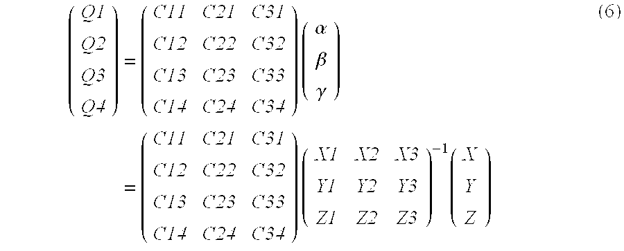
The display signal calculation unit 11 includes a linear signal calculation unit 14 and a gradation correcting unit 15 as shown in FIG. 6.
The linear signal calculation unit 14 calculates display signals (Q1, Q2, Q3, Q4) having a linear relationship to XYZ data, on the basis of the weighting factors and color reproduction area corner signals (C11, C12, C13, C14), (C21, C22, C23, C24) and (C31, C32, C33, C34) corresponding to color reproduction area corners P1, P2 and P3, using the following formula: ( Q1 Q2 Q3 Q4 ) = ( C11 C21 C31 C12 C22 C32 C13 C23 C33 C14 C24 C34 ) ( α β γ ) = ( C11 C21 C31 C12 C22 C32 C13 C23 C33 C14 C24 C34 ) ( X1 X2 X3 Y1 Y2 Y3 Z1 Z2 Z3 ) - 1 ( X Y Z ) ( 6 )
Figure US06538742-20030325-M00005
FIG. 8 shows the relationship between XYZ data and the color reproduction area corners P1, P2 and P3.
Display signals obtained using the formula (6) are identical to those obtained by multiplying, by a constant value k, input XYZ data to calculate signal values Q1m, Q2m, Q3m and Q4m that impart maximum brightness XYZ (XmYmZm) data, and then multiplying them by 1/k.
Since a signal value corresponding to XYZ data can be determined as an output-allowable signal on the color reproduction area surfaces of the display, a colorimetrically accurate signal value corresponding to XYZ data that is obtained by multiplying the XmYmZm data by a predetermined constant value and has a lower brightness than the XmYmZm data can be calculated using a single conversion matrix.
FIG. 9 two-dimensionally shows the relationship between XYZ data, maximum brightness XYZ data and the color reproduction area of the display.
The gradation correcting unit 15 subjects each linear signal (Q1, Q2, Q3, Q4) input from the linear signal calculation unit 14 to gradation correction using gradation characteristic data contained in the profile data, and outputs the correction results as display signals (C1, C2, C3, C4) to the output boards 7 and 8. Gradation correction is executed using formula (7) that includes an inverse function r−1 with respect to the gradation data which imparts output brightness values to input signals.
C 11 −1(Q 1)
C 22 −1(Q 2)
C 33 −1(Q 3)
C 44 −1(Q 4)  (7)
The above-described processing for obtaining a display signal from XYZ data is executed for each pixel, and the obtained display signal is input to the display unit. As a result, a colorimetrically accurate color image can be displayed.
Although in the embodiment, projectors are used as color image display units, the invention is not limited to this. The invention is also applicable to any optional display, such as a CRT display, a liquid crystal display, etc., which uses a mixture of primary color beams as a color reproduction principle.
Further, although the embodiment employs four primary colors, the number of primary colors is not limited to four, but any number N not less than three may be employed.
In this case, the number of planes that constitute the color reproduction area surfaces is N(N−1). Any primary color may be used, and the invention is not limited to such a color of a high chroma as employed in the embodiment.
Moreover, although four primary color display is realized by two projectors, a single projector may be used if it can execute four primary color display.
In addition, although in the embodiment, the color reproduction area corner XYZ data is calculated by adding, to a corresponding weighting factor, the XYZ data obtained when a primary color corresponding to a primary color signal is at its maximum emission, the XYZ data corresponding to each combination of primary color signals of each color reproduction area corner may be measured in advance as profile data. Since in this case, the measurement data can be used as the color reproduction area corner XYZ data, highly accurate conversion can be executed even in a display that cannot satisfy additive color mixture condition.
Referring then to FIG. 10, an example of an image processing apparatus according to a second embodiment of the invention will be described. This embodiment has a similar structure to the above-described first embodiment except for a color conversion unit 16, and therefore only the characterizing section, i.e. the color conversion unit 16, of the second embodiment will be described.
The color conversion unit 16 comprises a chromaticity area calculation unit 17, a profile data storage unit 18, a matrix data calculation unit 19, a matrix data storage unit 20, a matrix operation unit 21 and a gradation correcting unit 22.
The chromaticity area calculation unit 17 calculates XYZ data (color reproduction area corner XYZ data) corresponding to signals (color reproduction area corner signals) indicating the corners of the planes of the quadrilaterals that constitute the color reproduction area surfaces of the display, on the basis of combinations of XYZ data items stored in the profile data storage unit 18 and obtained when each primary color is at its maximum emission. The calculated data is input to the matrix data calculation unit 19.
The chromaticity area calculation unit 17 obtains an area of the chromaticity plane, which is enclosed by the color reproduction area corner XYZ data, and supplies it as chromaticity area data to the matrix data storage unit 20. The matrix data calculation unit 19 calculates color reproduction area corner XYZ data of three of the four corners obtained by the chromaticity area calculation unit 17, and color reproduction area corner signal values corresponding thereto, thereby calculating matrix data and inputting it to the matrix data storage unit 20. The matrix data storage unit 20 stores the matrix data in relation to chromaticity area data. The matrix data of a k-th color reproduction area surface is given by the following formula: ( d11 ( k ) d12 ( k ) d13 ( k ) d21 ( k ) d22 ( k ) d23 ( k ) d31 ( k ) d32 ( k ) d33 ( k ) d41 ( k ) d42 ( k ) d43 ( k ) ) = ( C11 ( k ) C21 ( k ) C31 ( k ) C12 ( k ) C22 ( k ) C32 ( k ) C13 ( k ) C23 ( k ) C33 ( k ) C14 ( k ) C24 ( k ) C34 ( k ) ) ( X1 ( k ) X2 ( k ) X3 ( k ) Y1 ( k ) Y2 ( k ) Y3 ( k ) Z1 ( k ) Z2 ( k ) Z2 ( k ) ) - 1 ( 8 )
Figure US06538742-20030325-M00006
where Cij(k) represents the j-th (j=1-4) signal value of the i-th (i=1-3) color reproduction area corner of the k-th (k=1-8) area. Similarly, Xi(k) represents the X data of the i-th corner of the k-th area. The same can be said of Y and Z.
As is shown in FIG. 11, the correspondence between matrix data and chromaticity areas is given by a two-dimensional table that stores an area number k using a predetermined sample chromaticity value as an address.
The above-mentioned processing is executed on all chromaticity areas k.
The matrix operation unit 21 converts XYZ data input from the image data input unit 1, into display signals using the pre-prepared matrix data and two-dimensional table data.
First, XYZ data is converted into chromaticity data xy, then the area number k to which the data xy belongs is obtained from the two-dimensional table, and display signals (Q1, Q2, Q3, Q4) are calculated using matrix data corresponding to k and the following formula: ( Q1 Q2 Q3 Q4 ) = ( d11 ( k ) d12 ( k ) d13 ( k ) d21 ( k ) d22 ( k ) d23 ( k ) d31 ( k ) d32 ( k ) d33 ( k ) d41 ( k ) d42 ( k ) d43 ( k ) ) ( X Y Z ) ( 9 )
Figure US06538742-20030325-M00007
The display signals are input to the gradation correcting unit 22, where they are corrected using gradation characteristic data contained in the profile data. The corrected data is output to the output boards 7 and 8.
Referring to FIG. 12, an example of an image processing apparatus according to a third embodiment of the invention will be described.
In the third embodiment, six primary color display is executed by six-primary-color display units 23-26 each including two projectors and a screen divided into four portions. More specifically, four combinations of projectors, i.e. eight projectors in total, are used to establish a six-primary-color overlapping display system with an enlarged color reproduction area, which can display very fine images.
For example, the six-primary-color display unit 23 consisting of projectors 23 a and 23 b displays a color image formed of six primary colors on a screen component A that constitutes an upper left portion of the screen. Similarly, projectors 24, 25 and 26 display images of six primary colors on screen components B, C and D, respectively.
This six-primary-color display system executes color conversion in a similar manner to the four-primary-color display employed in the first or second embodiment, and executes six primary color display by assigning three primary colors to each projector included in each combination.
FIG. 13 schematically illustrates a color reproduction area on the xy chromaticity diagram for the six-primary-color display.
In a multi-primary-color-overlapping display system such as a six-primary-color-overlapping display system, it is necessary to execute image positioning and color matching within each display area, as well as positioning of projected images in the different display areas.
A method for positioning to-be-overlapped images is disclosed in Japanese Patent Application KOKAI Publication No. 9-326981 proposed by the same applicant as the present application. This technique is also applicable to the positioning of images projected by two projectors that constitute a multi-primary-color display.
Further, although in an overlapping display system, it is also necessary to match to-be-overlapped images in color or brightness, this kind of matching is not a big problem in the system using projectors of the same type in which there is no great difference in structure and characteristics.
However, in a multi-primary-color-overlapping display system, a great number of primary colors are used and hence it is highly possible that even slight differences in structure and characteristics between projectors will cause not a slight influence on the entire image. Therefore, a color correction device is necessary for each display area.
FIG. 14 shows an image output device including a device for performing such correction.
The image output device employed in the third embodiment comprises a geometric correction unit 27 for performing correction, a color conversion unit 28 for creating, by conversion, a signal to be supplied to projectors, and output boards 29-32 for outputting image data to the respective projectors.
The geometric correction unit 27 creates X′ Y′ Z′ image data that is obtained on the basis of very fine image data consisting of the XYZ data of each pixel input by the image data input unit 1, and that is obtained by correcting the position of each projector and/or geometrical distortion of data input thereto. For further particulars concerning the correction processing of the geometric correction unit 27, see the aforementioned publication No. 9-326981.
The color conversion unit 28 converts XYZ image data to be input to each projector, into a signal to be input thereto on the basis of the profile data of each projector obtained by measurement. Since the color conversion method employed in the color conversion unit 28 is the same as that described in the second embodiment, no description will be given of the method.
FIG. 15 shows another example of the multi-primary-color-overlapping display system as a modification of the third embodiment. This system has a screen of a dome shape, i.e. a screen of a curved surface. It is a matter of course that the projection surface of the screen is not limited to this shape, but may be a flat surface, a spherical surface, a curved surface or a combined surface thereof. Basically, it suffices if a single projection surface is seen from the projector side. For example, the screen may have a stepped surface which is, however, seen flat from the projection side of the projectors. Alternatively, the screen may have a plurality of surfaces arranged parallel to each other so that they will be seen as a single projection surface from the projector side.
In the multi-primary-color-overlapping display system constructed as above, an image formed using an optional number of primary colors and consisting of an optional number of overlapping images can be projected on a screen of any desired shape, and a color image of an excellent color reproductivity, a wide angle of field and a high resolution can be displayed.
As described above in detail, the invention provides a color reproduction system including a multi-primary-color display, which can realize colorimetrically accurate color reproduction, continuity between XYZ data and signal values, and maximum use of its color reproduction area.
Additional advantages and modifications will readily occur to those skilled in the art. Therefore, the invention in its broader aspects is not limited to the specific details and representative embodiments shown and described herein. Accordingly, various modifications may be made without departing from the spirit or scope of the general inventive concept as defined by the appended claims and their equivalents.

Claims (22)

What is claimed is:
1. A color reproduction system having color image display means, arid color conversion means for converting input tristimulus values into a color image signal to be input to the color image display means, wherein the color conversion means comprises:
maximum brightness signal calculating means for calculating three color reproduction area corner vectors that indicate three corners of a plane constituting a color reproduction area surface of the color image display means, the three color reproduction area corner vectors surrounding vectors of the input tristimulus values, the maximum brightness signal calculating means also calculating a weighting factor obtained when the input tristimulus values are expressed as a linear sum of tristimulus values of the color reproduction area corner vectors; and
color image signal calculating means for calculating a color image signal used to display the input tristimulus values, on the basis of signal values corresponding to the color reproduction area corner vectors and the weighting factor.
2. A color reproduction system having color image display means, and color conversion means for converting input tristimulus values into a color image signal to be input to the color image display means, wherein the color conversion means comprises:
chromaticity area calculating means for calculating a chromaticity area surrounded by corners of planes constituting a color reproduction area surface of the color image display means;
matrix calculating means for calculating matrix data that provides a relationship between tristimulus values of the corners and the color image signal;
matrix data storage means for storing the matrix data in relation to the chromaticity area; and
color image signal calculating means for converting the input tristimulus values into the color image signal, using part of the matrix data selected on the basis of chromaticity values of the input tristimulus values.
3. A color reproduction system according to claim 1, further comprising profile data storage means storing profile data of the color image display means to be supplied to the color conversion means, the profile data including XYZ values obtained when each primary color is at its maximum emission and gradation characteristic data that provides a relationship between an input signal and emission brightness.
4. A color reproduction system according to claim 2, further comprising profile data storage means storing profile data of the color image display means to be supplied to the color conversion means, the profile data including gradation characteristic data that provides a relationship between XYZ values obtained when each primary color is at its maximum emission, an input signal and emission brightness.
5. A color reproduction system according to claim 1, wherein the color image display means includes a plurality of projectors for creating and projecting an image based on the color image signal and formed of an optional number of primary colors, the number of the projectors being determined on the basis of a necessary number of colors, the projectors projecting images onto a single screen such that the projected images constitute a single image.
6. A color reproduction system according to claim 2, wherein the color image display means includes a plurality of projectors for creating and projecting an image based on the color image signal and formed of an optional number of primary colors, the number of the projectors being determined on the basis of a necessary number of colors, the projectors projecting images onto a single screen such that the projected images constitute a single image.
7. A color reproduction system according to claim 3, wherein the color image display means includes a plurality of projectors for creating and projecting an image based on the color image signal and formed of an optional number of primary colors, the number of the projectors being determined on the basis of a necessary number of colors, the projectors projecting images onto a single screen such that the projected images constitute a single image.
8. A color reproduction system according to claim 5, wherein the single screen is divided into a plurality of areas, and the number of the projectors is determined on the basis of a necessary number of colors in each of the areas, the projectors projecting images onto the respective areas of the single screen such that the projected images constitute a single image.
9. A color reproduction system according to claim 6, wherein emission spectra of the projectors distribute in a visible wavelength range of 380 nm-780 nm.
10. A color reproduction system according to claim 7, wherein emission spectra of the projectors distribute in a visible wavelength range of 380 nm-780 nm.
11. A color reproduction system according to claim 8, wherein emission spectra of the projectors distribute in a visible wavelength range of 380 nm-780 nm.
12. A color reproduction system according to claim 5, wherein emission spectra of the projectors distribute in a visible wavelength range of 380 nm-780 nm.
13. A color reproduction system according to claim 1, wherein the color image display means includes a CRT display or a liquid crystal display, which performs color reproduction by mixing primary color beams.
14. A color reproduction system according to claim 2, wherein the color image display means includes a CRT display or a liquid crystal display, which performs color reproduction by mixing primary color beams.
15. A color reproduction system according to claim 3, wherein the color image display means includes a CRT display or a liquid crystal display, which performs color reproduction by mixing primary color beams.
16. A color reproduction system according to claim 4, wherein the color image display means includes a CRT display or a liquid crystal display, which performs color reproduction by mixing primary color beams.
17. A color reproduction system according to claim 5, wherein the color image display means includes a CRT display or a liquid crystal display, which performs color reproduction by mixing primary color beams.
18. A color reproduction system according to claim 6, wherein the color image display means includes a CRT display or a liquid crystal display, which performs color reproduction by mixing primary color beams.
19. A color reproduction system according to claim 5, wherein the single screen has a projection surface which is at least one of flat, spherical, and curved.
20. A color reproduction system according to claim 6, wherein the single screen is divided into a plurality of areas, and the number of the projectors is determined on the basis of a necessary number of colors in each of the plurality of areas, the projectors projecting images onto respective areas of the single screen such that the projected images constitute a single image.
21. A color reproduction system according to claim 4, wherein the color image display means includes a plurality of projectors which create and project an image based on the color image signal which is formed of primary colors, the number of the projectors being determined on the basis of a necessary number of colors, the projectors projecting images onto a single screen such that the projected images constitute a single image.
22. A color reproduction system according to claim 6, wherein the single screen has a projection surface which is at least one of flat, spherical, and curved.
US09/510,787 1999-02-25 2000-02-23 Color reproducing system Expired - Fee Related US6538742B1 (en)

Priority Applications (1)

Application Number Priority Date Filing Date Title
US10/372,348 US20030137610A1 (en) 1999-02-25 2003-02-24 Color reproducing system

Applications Claiming Priority (2)

Application Number Priority Date Filing Date Title
JP04804299A JP4197788B2 (en) 1999-02-25 1999-02-25 Color reproduction system
JP11-048042 1999-02-25

Related Child Applications (1)

Application Number Title Priority Date Filing Date
US10/372,348 Division US20030137610A1 (en) 1999-02-25 2003-02-24 Color reproducing system

Publications (1)

Publication Number Publication Date
US6538742B1 true US6538742B1 (en) 2003-03-25

Family

ID=12792281

Family Applications (2)

Application Number Title Priority Date Filing Date
US09/510,787 Expired - Fee Related US6538742B1 (en) 1999-02-25 2000-02-23 Color reproducing system
US10/372,348 Abandoned US20030137610A1 (en) 1999-02-25 2003-02-24 Color reproducing system

Family Applications After (1)

Application Number Title Priority Date Filing Date
US10/372,348 Abandoned US20030137610A1 (en) 1999-02-25 2003-02-24 Color reproducing system

Country Status (2)

Country Link
US (2) US6538742B1 (en)
JP (1) JP4197788B2 (en)

Cited By (39)

* Cited by examiner, † Cited by third party
Publication number Priority date Publication date Assignee Title
US20010024231A1 (en) * 2000-03-21 2001-09-27 Olympus Optical Co., Ltd. Stereoscopic image projection device, and correction amount computing device thereof
US20020021259A1 (en) * 2000-08-11 2002-02-21 Nec Viewtechnology, Ltd. Image display device
US20020149546A1 (en) * 2000-12-18 2002-10-17 Moshe Ben-Chorin Spectrally matched print proofer
US20030034992A1 (en) * 2001-05-09 2003-02-20 Clairvoyante Laboratories, Inc. Conversion of a sub-pixel format data to another sub-pixel data format
US20030098928A1 (en) * 2001-11-28 2003-05-29 Samsung Electronics Co., Ltd. Color signal processing device for multi-primary color display and method thereof
US20030214499A1 (en) * 1999-05-26 2003-11-20 Olympus Optical Co., Ltd. Color reproduction system for making color display of four or more primary colors based on input tristimulus values
US20040046939A1 (en) * 2002-05-23 2004-03-11 Olympus Optical Co., Ltd. Image display device
US20040100589A1 (en) * 2000-06-07 2004-05-27 Ilan Ben-David Device, system and method for electronic true color display
US20040150836A1 (en) * 2002-03-20 2004-08-05 Anton Kraus Method and device for determining the absolute coordinates of an object
US20040174389A1 (en) * 2001-06-11 2004-09-09 Ilan Ben-David Device, system and method for color display
US20040233339A1 (en) * 2003-05-20 2004-11-25 Elliott Candice Hellen Brown Projector systems with reduced flicker
US20040232844A1 (en) * 2003-05-20 2004-11-25 Brown Elliott Candice Hellen Subpixel rendering for cathode ray tube devices
US20040233308A1 (en) * 2003-05-20 2004-11-25 Elliott Candice Hellen Brown Image capture device and camera
US20040246389A1 (en) * 2002-07-24 2004-12-09 Shmuel Roth High brightness wide gamut display
US20040252130A1 (en) * 2003-06-05 2004-12-16 Samsung Electronics Co., Ltd. Color signal processing apparatus and method for reproducing colors on MPD
US20040263638A1 (en) * 2001-11-02 2004-12-30 Telecommunications Advancement Organization Of Japan Color reproduction system
WO2005032151A1 (en) * 2003-09-30 2005-04-07 Koninklijke Philips Electronics, N.V. Universal color decoder and method for decoding input signal for a multiple primary color display system
US20050104908A1 (en) * 2001-05-09 2005-05-19 Clairvoyante Laboratories, Inc. Color display pixel arrangements and addressing means
US20050122294A1 (en) * 2002-04-11 2005-06-09 Ilan Ben-David Color display devices and methods with enhanced attributes
US20050190141A1 (en) * 2002-01-07 2005-09-01 Shmuel Roth Device and method for projection device based soft proofing
US20050270637A1 (en) * 2004-06-04 2005-12-08 Prodisc Technology Inc. Display device
US20050271291A1 (en) * 2004-06-04 2005-12-08 Nai-Yueh Liang Image processing method for display device
US20060001893A1 (en) * 2004-07-05 2006-01-05 Prodisc Technology Inc. Display device and image processing method therefor
US20060001957A1 (en) * 2004-07-05 2006-01-05 Prodisc Technology Inc. Display device and image processing method therefor
EP1676254A2 (en) * 2003-10-21 2006-07-05 Clairvoyante, Inc. Method and apparatus for converting from a source color space to a target color space
US20060187231A1 (en) * 2001-09-18 2006-08-24 Canon Kabushiki Kaisha Image data processing method and apparatus, storage medium product, and program product
US20060285217A1 (en) * 2003-08-04 2006-12-21 Genoa Color Technologies Ltd. Multi-primary color display
US20070001994A1 (en) * 2001-06-11 2007-01-04 Shmuel Roth Multi-primary display with spectrally adapted back-illumination
US7164429B1 (en) 2004-07-07 2007-01-16 Hewlett-Packard Development Company, L.P. Signal conversion system
US20090091582A1 (en) * 2005-05-23 2009-04-09 Olympus Corporation Multi-primary color display method and device
US20090116085A1 (en) * 2007-11-07 2009-05-07 Victor Company Of Japan, Limited Optical system and projection display device
US20090135129A1 (en) * 2001-06-11 2009-05-28 Shmuel Roth Method, device and system for multi-color sequential lcd panel
US20090179826A1 (en) * 2005-11-28 2009-07-16 Doron Malka Sub-pixel rendering of a multiprimary image
US20100097406A1 (en) * 2008-10-21 2010-04-22 Zulch Laboratories, Inc. Color generation using multiple illuminant types
US20110170074A1 (en) * 2009-11-06 2011-07-14 Bran Ferren System for providing an enhanced immersive display environment
US8228275B2 (en) 2003-01-28 2012-07-24 Genoa Color Technologies Ltd. Optimal subpixel arrangement for displays with more than three primary colors
US20130176539A1 (en) * 2010-09-10 2013-07-11 Lemoptix Sa Method and device for projecting a 3-d viewable image
US20170038196A1 (en) * 2014-02-19 2017-02-09 Andong National University Industry-Academic Cooperation Foundation System and method for acquiring color image from monochrome scan camera
US10855962B2 (en) * 2018-08-30 2020-12-01 Seiko Epson Corporation Projector, color correction system, and control method of projector

Families Citing this family (39)

* Cited by examiner, † Cited by third party
Publication number Priority date Publication date Assignee Title
DE60237084D1 (en) 2001-06-07 2010-09-02 Genoa Color Technologies Ltd DATA PROCESSING SYSTEM AND METHOD FOR BIG LEADER INDICATORS
US6962414B2 (en) 2001-07-12 2005-11-08 Genoa Color Technologies Ltd. Sequential projection color display using multiple imaging panels
WO2003010745A1 (en) 2001-07-23 2003-02-06 Genoa Technologies Ltd. Display for simulation of printed material
US6897876B2 (en) * 2003-06-26 2005-05-24 Eastman Kodak Company Method for transforming three color input signals to four or more output signals for a color display
US7483095B2 (en) 2003-12-15 2009-01-27 Genoa Color Technologies Ltd Multi-primary liquid crystal display
US7495722B2 (en) 2003-12-15 2009-02-24 Genoa Color Technologies Ltd. Multi-color liquid crystal display
KR101012790B1 (en) 2003-12-30 2011-02-08 삼성전자주식회사 Apparatus and method of converting image signal for four color display device, and display device comprising the same
DE602004028572D1 (en) 2004-04-30 2010-09-23 Samsung Electronics Co Ltd Apparatus and method for image multicolor transformation
JP4925602B2 (en) * 2004-04-30 2012-05-09 三星電子株式会社 Multicolor conversion device for video, multicolor conversion method for video, and recording medium
US7407295B2 (en) * 2005-07-26 2008-08-05 Niranjan Damera-Venkata Projection of overlapping sub-frames onto a surface using light sources with different spectral distributions
JP4976782B2 (en) * 2005-09-07 2012-07-18 キヤノン株式会社 Signal processing method, image display device, and television device
JP2007116288A (en) * 2005-10-18 2007-05-10 Seiko Epson Corp Image processor, image processing method, and image processing program
JP2007274600A (en) * 2006-03-31 2007-10-18 National Univ Corp Shizuoka Univ Color conversion matrix forming method and color conversion apparatus
US8115410B2 (en) * 2006-12-08 2012-02-14 Koninklijke Philips Electronics N.V. Device for generating light with a variable color
KR101348369B1 (en) 2007-11-12 2014-01-07 삼성전자주식회사 Color conversion method and apparatus for display device
US11532261B1 (en) 2018-10-25 2022-12-20 Baylor University System and method for a multi-primary wide gamut color system
US11037481B1 (en) 2018-10-25 2021-06-15 Baylor University System and method for a multi-primary wide gamut color system
US11373575B2 (en) 2018-10-25 2022-06-28 Baylor University System and method for a multi-primary wide gamut color system
US10950162B2 (en) 2018-10-25 2021-03-16 Baylor University System and method for a six-primary wide gamut color system
US11062638B2 (en) 2018-10-25 2021-07-13 Baylor University System and method for a multi-primary wide gamut color system
US11069279B2 (en) 2018-10-25 2021-07-20 Baylor University System and method for a multi-primary wide gamut color system
US11030934B2 (en) 2018-10-25 2021-06-08 Baylor University System and method for a multi-primary wide gamut color system
US11403987B2 (en) 2018-10-25 2022-08-02 Baylor University System and method for a multi-primary wide gamut color system
US11475819B2 (en) 2018-10-25 2022-10-18 Baylor University System and method for a multi-primary wide gamut color system
US10607527B1 (en) 2018-10-25 2020-03-31 Baylor University System and method for a six-primary wide gamut color system
US11488510B2 (en) 2018-10-25 2022-11-01 Baylor University System and method for a multi-primary wide gamut color system
US10950161B2 (en) 2018-10-25 2021-03-16 Baylor University System and method for a six-primary wide gamut color system
US11043157B2 (en) 2018-10-25 2021-06-22 Baylor University System and method for a six-primary wide gamut color system
US10997896B2 (en) 2018-10-25 2021-05-04 Baylor University System and method for a six-primary wide gamut color system
US11315467B1 (en) 2018-10-25 2022-04-26 Baylor University System and method for a multi-primary wide gamut color system
US11289003B2 (en) 2018-10-25 2022-03-29 Baylor University System and method for a multi-primary wide gamut color system
US11069280B2 (en) 2018-10-25 2021-07-20 Baylor University System and method for a multi-primary wide gamut color system
US11189210B2 (en) 2018-10-25 2021-11-30 Baylor University System and method for a multi-primary wide gamut color system
US11410593B2 (en) 2018-10-25 2022-08-09 Baylor University System and method for a multi-primary wide gamut color system
US11289000B2 (en) 2018-10-25 2022-03-29 Baylor University System and method for a multi-primary wide gamut color system
US11341890B2 (en) 2018-10-25 2022-05-24 Baylor University System and method for a multi-primary wide gamut color system
US11587491B1 (en) 2018-10-25 2023-02-21 Baylor University System and method for a multi-primary wide gamut color system
CN111901578B (en) * 2020-06-28 2021-10-22 成都威爱新经济技术研究院有限公司 Multi-channel cave type projection method
AU2021351632A1 (en) * 2020-10-01 2023-05-18 Baylor University System and method for a multi-primary wide gamut color system

Citations (8)

* Cited by examiner, † Cited by third party
Publication number Priority date Publication date Assignee Title
US4500919A (en) * 1982-05-04 1985-02-19 Massachusetts Institute Of Technology Color reproduction system
JPH06261332A (en) 1993-03-03 1994-09-16 Nippon Hoso Kyokai <Nhk> Primary color conversion method for multiple primary colors display
US5579031A (en) * 1992-12-15 1996-11-26 E. I. Du Pont De Nemours And Company Color matching method and apparatus
US5583666A (en) * 1993-02-12 1996-12-10 Eastman Kodak Company Method for cross-device color calibration and enhancement using explicit constraints
JPH09326981A (en) 1996-06-06 1997-12-16 Olympus Optical Co Ltd Image projection system
US6101272A (en) * 1996-12-12 2000-08-08 Fuji Photo Film Co., Ltd. Color transforming method
US6225974B1 (en) 1997-06-19 2001-05-01 Electronics For Imaging, Inc. Gamut correction with color separation and methods and apparatuses for performing same
US6262744B1 (en) 1996-05-07 2001-07-17 Barco N.V. Wide gamut display driver

Family Cites Families (4)

* Cited by examiner, † Cited by third party
Publication number Priority date Publication date Assignee Title
US5534949A (en) * 1994-04-08 1996-07-09 Hughes Aircraft Company Two channel field sequential color display system
US6377230B1 (en) * 1995-10-05 2002-04-23 Semiconductor Energy Laboratory Co., Ltd. Three dimensional display unit and display method
IL119259A (en) * 1996-09-17 2000-12-06 Comview Graphics Ltd Electro-optical display apparatus and method of using same
US5921650A (en) * 1998-02-27 1999-07-13 International Business Machines Corporation High efficiency field-sequential color projector using two SLMs

Patent Citations (8)

* Cited by examiner, † Cited by third party
Publication number Priority date Publication date Assignee Title
US4500919A (en) * 1982-05-04 1985-02-19 Massachusetts Institute Of Technology Color reproduction system
US5579031A (en) * 1992-12-15 1996-11-26 E. I. Du Pont De Nemours And Company Color matching method and apparatus
US5583666A (en) * 1993-02-12 1996-12-10 Eastman Kodak Company Method for cross-device color calibration and enhancement using explicit constraints
JPH06261332A (en) 1993-03-03 1994-09-16 Nippon Hoso Kyokai <Nhk> Primary color conversion method for multiple primary colors display
US6262744B1 (en) 1996-05-07 2001-07-17 Barco N.V. Wide gamut display driver
JPH09326981A (en) 1996-06-06 1997-12-16 Olympus Optical Co Ltd Image projection system
US6101272A (en) * 1996-12-12 2000-08-08 Fuji Photo Film Co., Ltd. Color transforming method
US6225974B1 (en) 1997-06-19 2001-05-01 Electronics For Imaging, Inc. Gamut correction with color separation and methods and apparatuses for performing same

Non-Patent Citations (2)

* Cited by examiner, † Cited by third party
Title
"Color Image Duplication", pp. 136-137, Johji Tajima, Maruzen Co., Ltd., Tokyo, Japan, Sep. 30, 1996.
"Introduction to Color Reproduction Technology", pp. 37-39, Noburo Ohta, Corona Publishing Co., Ltd., Tokyo, Japan, Sep. 10, 1997.

Cited By (93)

* Cited by examiner, † Cited by third party
Publication number Priority date Publication date Assignee Title
US7511715B2 (en) 1999-05-26 2009-03-31 Olympus Optical Co., Ltd. Color reproduction system for making color display of four or more primary colors based on input tristimulus values
US20030214499A1 (en) * 1999-05-26 2003-11-20 Olympus Optical Co., Ltd. Color reproduction system for making color display of four or more primary colors based on input tristimulus values
US6873339B2 (en) * 1999-05-26 2005-03-29 Olympus Optical Co., Ltd. Color reproduction system for making color display of four or more primary colors based on input tristimulus values
US20010024231A1 (en) * 2000-03-21 2001-09-27 Olympus Optical Co., Ltd. Stereoscopic image projection device, and correction amount computing device thereof
US6870523B1 (en) 2000-06-07 2005-03-22 Genoa Color Technologies Device, system and method for electronic true color display
US7113152B2 (en) 2000-06-07 2006-09-26 Genoa Color Technologies Ltd. Device, system and method for electronic true color display
US20040100589A1 (en) * 2000-06-07 2004-05-27 Ilan Ben-David Device, system and method for electronic true color display
US20020021259A1 (en) * 2000-08-11 2002-02-21 Nec Viewtechnology, Ltd. Image display device
US20080218784A1 (en) * 2000-12-18 2008-09-11 Moshe Ben-Chorin Spectrally matched print proofer
US20020149546A1 (en) * 2000-12-18 2002-10-17 Moshe Ben-Chorin Spectrally matched print proofer
US7352488B2 (en) 2000-12-18 2008-04-01 Genoa Color Technologies Ltd Spectrally matched print proofer
US8310498B2 (en) 2000-12-18 2012-11-13 Samsung Display Co., Ltd. Spectrally matched print proofer
US7864202B2 (en) 2001-05-09 2011-01-04 Samsung Electronics Co., Ltd. Conversion of a sub-pixel format data to another sub-pixel data format
US7689058B2 (en) 2001-05-09 2010-03-30 Samsung Electronics Co., Ltd. Conversion of a sub-pixel format data to another sub-pixel data format
US7688335B2 (en) 2001-05-09 2010-03-30 Samsung Electronics Co., Ltd. Conversion of a sub-pixel format data to another sub-pixel data format
US7916156B2 (en) 2001-05-09 2011-03-29 Samsung Electronics Co., Ltd. Conversion of a sub-pixel format data to another sub-pixel data format
US8223168B2 (en) 2001-05-09 2012-07-17 Samsung Electronics Co., Ltd. Conversion of a sub-pixel format data
US7889215B2 (en) 2001-05-09 2011-02-15 Samsung Electronics Co., Ltd. Conversion of a sub-pixel format data to another sub-pixel data format
US7307646B2 (en) 2001-05-09 2007-12-11 Clairvoyante, Inc Color display pixel arrangements and addressing means
US20070153027A1 (en) * 2001-05-09 2007-07-05 Clairvoyante, Inc Conversion of a sub-pixel format data to another sub-pixel data format
US20050104908A1 (en) * 2001-05-09 2005-05-19 Clairvoyante Laboratories, Inc. Color display pixel arrangements and addressing means
US20070071352A1 (en) * 2001-05-09 2007-03-29 Clairvoyante, Inc Conversion of a sub-pixel format data to another sub-pixel data format
US20030034992A1 (en) * 2001-05-09 2003-02-20 Clairvoyante Laboratories, Inc. Conversion of a sub-pixel format data to another sub-pixel data format
US20070001994A1 (en) * 2001-06-11 2007-01-04 Shmuel Roth Multi-primary display with spectrally adapted back-illumination
US20080192178A1 (en) * 2001-06-11 2008-08-14 Ilan Ben-David Device, system and method for color display
US9196203B2 (en) 2001-06-11 2015-11-24 Samsung Display Co., Ltd. Device and system for a multi-color sequential LCD panel wherein the number of colors in a sequence of display colors is greater than the number of LED colors
US8885120B2 (en) 2001-06-11 2014-11-11 Genoa Color Technologies Ltd. Liquid crystal display device using a color-sequential method wherein the number of different colored LEDs is less than the number of primary colors used in the display
US8558857B2 (en) 2001-06-11 2013-10-15 Genoa Color Technologies Ltd. Device, system and method for color display
EP2273481A2 (en) * 2001-06-11 2011-01-12 Genoa Color Technologies Ltd. Device, system and method for color display
US7990403B2 (en) 2001-06-11 2011-08-02 Genoa Color Technologies Ltd. Device, system and method for color display
US20090135129A1 (en) * 2001-06-11 2009-05-28 Shmuel Roth Method, device and system for multi-color sequential lcd panel
US7995019B2 (en) 2001-06-11 2011-08-09 Genoa Color Technologies Ltd. Device, system and method for color display
US7714824B2 (en) 2001-06-11 2010-05-11 Genoa Color Technologies Ltd. Multi-primary display with spectrally adapted back-illumination
US8289266B2 (en) 2001-06-11 2012-10-16 Genoa Color Technologies Ltd. Method, device and system for multi-color sequential LCD panel
US20040174389A1 (en) * 2001-06-11 2004-09-09 Ilan Ben-David Device, system and method for color display
US8248440B2 (en) 2001-06-11 2012-08-21 Genoa Color Technologies Ltd. Device, system and method for color display
US9430974B2 (en) 2001-06-11 2016-08-30 Samsung Display Co., Ltd. Multi-primary display with spectrally adapted back-illumination
US20080030447A1 (en) * 2001-06-11 2008-02-07 Ilan Ben-David Device, system and method for color display
US20100214311A1 (en) * 2001-06-11 2010-08-26 Shmuel Roth Multi-primary display with spectrally adapted back-illumination
US9851599B2 (en) 2001-06-11 2017-12-26 Samsung Display Co., Ltd. Color display device comprising at least six different primary colors
US7268757B2 (en) 2001-06-11 2007-09-11 Genoa Color Technologies Ltd Device, system and method for color display
US20080024410A1 (en) * 2001-06-11 2008-01-31 Ilan Ben-David Device, system and method for color display
US7750921B2 (en) * 2001-09-18 2010-07-06 Canon Kabushiki Kaisha Image data processing method and apparatus, storage medium product, and program product
US20060187231A1 (en) * 2001-09-18 2006-08-24 Canon Kabushiki Kaisha Image data processing method and apparatus, storage medium product, and program product
EP1450302A4 (en) * 2001-11-02 2006-10-04 Telecomm Advancement Org Japan Color reproduction system
US20040263638A1 (en) * 2001-11-02 2004-12-30 Telecommunications Advancement Organization Of Japan Color reproduction system
US7199839B2 (en) * 2001-11-28 2007-04-03 Samsung Electronics Co., Ltd. Color signal processing device for multi-primary color display and method thereof
US20030098928A1 (en) * 2001-11-28 2003-05-29 Samsung Electronics Co., Ltd. Color signal processing device for multi-primary color display and method thereof
US7999823B2 (en) 2002-01-07 2011-08-16 Samsung Electronics Co., Ltd. Device and method for projection device based soft proofing
US20050190141A1 (en) * 2002-01-07 2005-09-01 Shmuel Roth Device and method for projection device based soft proofing
US6876458B2 (en) * 2002-03-20 2005-04-05 Steinbichler Optotechnik Gmbh Method and device for determining the absolute coordinates of an object
US20040150836A1 (en) * 2002-03-20 2004-08-05 Anton Kraus Method and device for determining the absolute coordinates of an object
US20050122294A1 (en) * 2002-04-11 2005-06-09 Ilan Ben-David Color display devices and methods with enhanced attributes
US9953590B2 (en) 2002-04-11 2018-04-24 Samsung Display Co., Ltd. Color display devices and methods with enhanced attributes
US20040046939A1 (en) * 2002-05-23 2004-03-11 Olympus Optical Co., Ltd. Image display device
US6984043B2 (en) * 2002-05-23 2006-01-10 Olympus Optical Co., Ltd. Image display apparatus for displaying superimposed images from a plurality of projectors
US7916939B2 (en) 2002-07-24 2011-03-29 Samsung Electronics Co., Ltd. High brightness wide gamut display
US20040246389A1 (en) * 2002-07-24 2004-12-09 Shmuel Roth High brightness wide gamut display
US20100134515A1 (en) * 2002-07-24 2010-06-03 Shmuel Roth High brightness wide gamut display
US7471822B2 (en) 2002-07-24 2008-12-30 Genoa Color Technologies Ltd Method and apparatus for high brightness wide color gamut display
US8228275B2 (en) 2003-01-28 2012-07-24 Genoa Color Technologies Ltd. Optimal subpixel arrangement for displays with more than three primary colors
US20040233308A1 (en) * 2003-05-20 2004-11-25 Elliott Candice Hellen Brown Image capture device and camera
US20040232844A1 (en) * 2003-05-20 2004-11-25 Brown Elliott Candice Hellen Subpixel rendering for cathode ray tube devices
US20040233339A1 (en) * 2003-05-20 2004-11-25 Elliott Candice Hellen Brown Projector systems with reduced flicker
US6922198B2 (en) 2003-06-05 2005-07-26 Samsung Electronics Co., Ltd Color signal processing apparatus and method for reproducing colors on MPD
US20040252130A1 (en) * 2003-06-05 2004-12-16 Samsung Electronics Co., Ltd. Color signal processing apparatus and method for reproducing colors on MPD
US7417799B2 (en) 2003-08-04 2008-08-26 Genoa Color Technologies Ltd. Multi-primary color display
US20060285217A1 (en) * 2003-08-04 2006-12-21 Genoa Color Technologies Ltd. Multi-primary color display
WO2005032151A1 (en) * 2003-09-30 2005-04-07 Koninklijke Philips Electronics, N.V. Universal color decoder and method for decoding input signal for a multiple primary color display system
US20070076014A1 (en) * 2003-09-30 2007-04-05 Koninklijke Philips Electronics N.V. Universal color decoder an method for decoding input signal for a multiple primary color display system
EP2309760A3 (en) * 2003-10-21 2011-04-20 Samsung Electronics Co., Ltd. Method and apparatus for efficiently calculating multiprimary color conversion matrices
EP1676254A4 (en) * 2003-10-21 2010-09-08 Samsung Electronics Co Ltd Method and apparatus for converting from a source color space to a target color space
EP1676254A2 (en) * 2003-10-21 2006-07-05 Clairvoyante, Inc. Method and apparatus for converting from a source color space to a target color space
US20050271291A1 (en) * 2004-06-04 2005-12-08 Nai-Yueh Liang Image processing method for display device
US20050270637A1 (en) * 2004-06-04 2005-12-08 Prodisc Technology Inc. Display device
US20060001957A1 (en) * 2004-07-05 2006-01-05 Prodisc Technology Inc. Display device and image processing method therefor
US20060001893A1 (en) * 2004-07-05 2006-01-05 Prodisc Technology Inc. Display device and image processing method therefor
US7164429B1 (en) 2004-07-07 2007-01-16 Hewlett-Packard Development Company, L.P. Signal conversion system
US20090091582A1 (en) * 2005-05-23 2009-04-09 Olympus Corporation Multi-primary color display method and device
US20090179826A1 (en) * 2005-11-28 2009-07-16 Doron Malka Sub-pixel rendering of a multiprimary image
US8587621B2 (en) 2005-11-28 2013-11-19 Genoa Color Technologies Ltd. Sub-pixel rendering of a multiprimary image
US20090116085A1 (en) * 2007-11-07 2009-05-07 Victor Company Of Japan, Limited Optical system and projection display device
US7686455B2 (en) * 2007-11-07 2010-03-30 Victor Company Of Japan, Limited Optical system and projection display device
US8497871B2 (en) 2008-10-21 2013-07-30 Zulch Laboratories, Inc. Color generation using multiple illuminant types
US8665296B2 (en) 2008-10-21 2014-03-04 Zulch Laboratories, Inc. Color generation change using multiple illuminant types
US20100097406A1 (en) * 2008-10-21 2010-04-22 Zulch Laboratories, Inc. Color generation using multiple illuminant types
US20100097407A1 (en) * 2008-10-21 2010-04-22 Zulch Laboratories, Inc. Color generation change using multiple illuminant types
US20110170074A1 (en) * 2009-11-06 2011-07-14 Bran Ferren System for providing an enhanced immersive display environment
US9465283B2 (en) * 2009-11-06 2016-10-11 Applied Minds, Llc System for providing an enhanced immersive display environment
US20130176539A1 (en) * 2010-09-10 2013-07-11 Lemoptix Sa Method and device for projecting a 3-d viewable image
US9164368B2 (en) * 2010-09-10 2015-10-20 Intel Corporation Method and device for projecting a 3-D viewable image
US20170038196A1 (en) * 2014-02-19 2017-02-09 Andong National University Industry-Academic Cooperation Foundation System and method for acquiring color image from monochrome scan camera
US10855962B2 (en) * 2018-08-30 2020-12-01 Seiko Epson Corporation Projector, color correction system, and control method of projector

Also Published As

Publication number Publication date
JP2000253263A (en) 2000-09-14
US20030137610A1 (en) 2003-07-24
JP4197788B2 (en) 2008-12-17

Similar Documents

Publication Publication Date Title
US6538742B1 (en) Color reproducing system
US7511715B2 (en) Color reproduction system for making color display of four or more primary colors based on input tristimulus values
KR100566164B1 (en) Image displaying method and image displaying device
Wallace et al. Color gamut matching for tiled display walls
US7453475B2 (en) Optical display device, program for controlling the optical display device, and method of controlling the optical display device
US6219011B1 (en) Electro-optical display apparatus
JP4363720B2 (en) A device for creating color palettes
Majumder et al. Perceptual photometric seamlessness in projection-based tiled displays
US7088478B2 (en) Chromaticity conversion device and chromaticity conversion method
KR20030031175A (en) Electronic calibration for seamless tiled display using optical function generator
US8805060B2 (en) Color conversion device, image output device, and color conversion method
US20050140612A1 (en) Display device and driving method thereof
US20060203202A1 (en) Image display device and projector
Stone Color balancing experimental projection displays
JP4145888B2 (en) Display device and display method
US6817721B1 (en) System and method for correcting projector non-uniformity
US7609230B2 (en) Display method and system using transmissive and emissive components
WO2020042566A1 (en) System and method for dynamically adjusting color gamut of display system, and display system
JP2001318651A (en) Method for compensating nonuniformity of display by change in primary color of color monitor
Majumder Contrast enhancement of multi-displays using human contrast sensitivity
US7319439B2 (en) Image display device and projector
Kresse et al. Color consistency for digital multi-projector stereo display systems: the heyewall and the digital cave
Majumder et al. Display gamut reshaping for color emulation and balancing
WO2005076252A1 (en) Multi-primary color display and color conversion method for multi-primary color display
Leachtenauer Electronic image display: equipment selection and operation

Legal Events

Date Code Title Description
AS Assignment

Owner name: OLYMPUS OPTICAL CO., LTD., JAPAN

Free format text: ASSIGNMENT OF ASSIGNORS INTEREST;ASSIGNOR:OHSAWA, KENRO;REEL/FRAME:010626/0427

Effective date: 20000214

FEPP Fee payment procedure

Free format text: PAYER NUMBER DE-ASSIGNED (ORIGINAL EVENT CODE: RMPN); ENTITY STATUS OF PATENT OWNER: LARGE ENTITY

Free format text: PAYOR NUMBER ASSIGNED (ORIGINAL EVENT CODE: ASPN); ENTITY STATUS OF PATENT OWNER: LARGE ENTITY

FEPP Fee payment procedure

Free format text: PAYOR NUMBER ASSIGNED (ORIGINAL EVENT CODE: ASPN); ENTITY STATUS OF PATENT OWNER: LARGE ENTITY

FPAY Fee payment

Year of fee payment: 4

REMI Maintenance fee reminder mailed
LAPS Lapse for failure to pay maintenance fees
STCH Information on status: patent discontinuation

Free format text: PATENT EXPIRED DUE TO NONPAYMENT OF MAINTENANCE FEES UNDER 37 CFR 1.362

FP Lapsed due to failure to pay maintenance fee

Effective date: 20110325