US6536812B1 - Adjustable-backset latch system for locksets, and method - Google Patents
Adjustable-backset latch system for locksets, and method Download PDFInfo
- Publication number
- US6536812B1 US6536812B1 US09/636,489 US63648900A US6536812B1 US 6536812 B1 US6536812 B1 US 6536812B1 US 63648900 A US63648900 A US 63648900A US 6536812 B1 US6536812 B1 US 6536812B1
- Authority
- US
- United States
- Prior art keywords
- bolt
- backset
- adjuster
- link
- pin
- Prior art date
- Legal status (The legal status is an assumption and is not a legal conclusion. Google has not performed a legal analysis and makes no representation as to the accuracy of the status listed.)
- Expired - Lifetime
Links
Images


Classifications
-
- E—FIXED CONSTRUCTIONS
- E05—LOCKS; KEYS; WINDOW OR DOOR FITTINGS; SAFES
- E05B—LOCKS; ACCESSORIES THEREFOR; HANDCUFFS
- E05B63/00—Locks or fastenings with special structural characteristics
- E05B63/06—Locks or fastenings with special structural characteristics with lengthwise-adjustable bolts ; with adjustable backset, i.e. distance from door edge
-
- E—FIXED CONSTRUCTIONS
- E05—LOCKS; KEYS; WINDOW OR DOOR FITTINGS; SAFES
- E05B—LOCKS; ACCESSORIES THEREFOR; HANDCUFFS
- E05B55/00—Locks in which a sliding latch is used also as a locking bolt
- E05B55/005—Cylindrical or tubular locks
-
- Y—GENERAL TAGGING OF NEW TECHNOLOGICAL DEVELOPMENTS; GENERAL TAGGING OF CROSS-SECTIONAL TECHNOLOGIES SPANNING OVER SEVERAL SECTIONS OF THE IPC; TECHNICAL SUBJECTS COVERED BY FORMER USPC CROSS-REFERENCE ART COLLECTIONS [XRACs] AND DIGESTS
- Y10—TECHNICAL SUBJECTS COVERED BY FORMER USPC
- Y10S—TECHNICAL SUBJECTS COVERED BY FORMER USPC CROSS-REFERENCE ART COLLECTIONS [XRACs] AND DIGESTS
- Y10S292/00—Closure fasteners
- Y10S292/60—Adjustment provisions
-
- Y—GENERAL TAGGING OF NEW TECHNOLOGICAL DEVELOPMENTS; GENERAL TAGGING OF CROSS-SECTIONAL TECHNOLOGIES SPANNING OVER SEVERAL SECTIONS OF THE IPC; TECHNICAL SUBJECTS COVERED BY FORMER USPC CROSS-REFERENCE ART COLLECTIONS [XRACs] AND DIGESTS
- Y10—TECHNICAL SUBJECTS COVERED BY FORMER USPC
- Y10T—TECHNICAL SUBJECTS COVERED BY FORMER US CLASSIFICATION
- Y10T292/00—Closure fasteners
- Y10T292/06—Adjustable backset
Definitions
- the invention relates to an adjustable-backset latch system for locksets, and a method for adjusting backset and assembling the latch system.
- the latch system enables the user to quickly change a backset by the usual backset increment of 3 ⁇ 8′′ by simply moving a pin through a “U”-shaped slot in a housing member without having to rotate any of the components of the backset latch system.
- the invention also includes improved deadlatching and bolt retraction systems.
- the invention also includes the combination of the latch system with a lockset.
- an adjustable-backset latch system in which the user need only move a detent pin along a “U”-shaped slot in the latch housing to change the backset, without affecting the ability of a bolt operator to retract the latch bolt. It is another object of the present invention to provide a unique adjuster for coordinating the timing and operation of a bolt retraction system and a backset adjustment system. It is still another object of the present invention to provide an improved deadlatching system in which a deadlocking dog cooperates with a housing and a latch bolt and an auxiliary bolt to reliably and consistently provide the deadlatching function.
- a feature by which the above objects can be obtained is by providing a resilient adjuster mounted in one of a set of inner and outer cases which releasably couples the inner and outer cases and front and back links, which together make up a bolt actuator.
- the adjuster includes a member which is engageable by a person to cause the adjuster both to uncouple the cases and links, and to simultaneously adjust the links and cases by a predetermined backset increment.
- Another feature by which the above objects can be attained is by providing a bolt actuation system in which the bolt actuator, responsive to rotation of a bolt operator retracts a linkage that pulls a cam against a portion of the bolt, in such a manner as to multiply the linear travel of the bolt operator to achieve complete bolt retraction. Still another feature by which the above objects can be attained is by providing a deadlatching system in which a spring dog is mounted between a deadlocking dog and an auxiliary bolt such that not only is the auxiliary bolt biased normally to its extended position, but the deadlocking dog is simultaneously biased to a position which blocks the retraction of a main bolt. Still other features by which the above objects may be attained is by forming fastener clearance holes in both the housing and the adjuster, thereby yielding a compact yet structurally sound system.
- Still another object of the present invention is to provide a lockset having one or more handles and knobs which uses one or more elements of the adjuster-backset latch of the present invention.
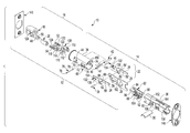
- FIG. 1 is a exploded perspective view of the adjustable backset latch mechanism of the present invention, schematically showing the bolt operator or “half-round”;
- FIG. 2 is an exploded perspective view of the adjustable backset of FIG. 1, rotated 180 degrees;
- FIGS. 3, 4 and 5 are sequential sectional detail views of the bolt retraction system of the latch mechanism of the present invention, with FIG. 3 showing the bolt fully extended, FIG. 4 showing the bolt half-way retracted and FIG. 5 showing the bolt fully retracted, the bolt actuator being formed by the back link connected to the front link(s);
- FIG. 3A is an enlarged schematic detail view of the cam of the present invention shown in FIG. 3;
- FIG. 6 is an enlarged perspective detail view of the adjuster of the present invention.
- FIG. 7 is a series of sequential views showing the operation of the dead latching locking and releasing mechanism of the present invention.
- FIG. 8 is a set of enlarged perspective detail views showing the use of a low-friction insert in the bolt subassembly
- FIG. 9 is a set of enlarged perspective detail views showing the use of a low-friction sleeve in the bolt/latch front plate subassembly
- FIGS. 10 through 19 are step-by-step Figures showing the sequence of operation of a backset adjusting system of the present invention.
- FIGS. 10 and 11 are sectional detail views of the backset set at 23 ⁇ 8′′ with the detent pin “up”,
- FIGS. 12 and 13 are sectional detail views of the backset adjustment system set at the 23 ⁇ 8′′ backset, with the detent pin “down”;
- FIGS. 14 and 15 are sectional detail views of the backset adjustment system of the present invention with the 23 ⁇ 8′′ backset, during adjustment;
- FIGS. 16 and 17 are sectional detail views of the backset adjustment system of the present invention set at a 23 ⁇ 4′′ backset with the detent pin “down”;
- FIGS. 18 and 19 are sectional detail views of the backset adjustment system of the present invention set at 23 ⁇ 4′′ backset, with the detent pin “up”;
- FIGS. 20 through 30 are sequential exploded perspective detail views of the sequence of assembly of the adjustable backset latch mechanism of the present invention.
- FIG. 31 is a sectional detail view of the adjustable backset latch mechanism of the present invention showing an alternative embodiment involving a different method of attaching the deadlocking dog holder to the outer case;
- FIG. 32 is an exploded perspective detail view of the new outer case and holder configuration associated with the second embodiment of the present invention.
- FIG. 33 is an exploded perspective detail view of the second embodiment of the adjustable backset latch mechanism of the present invention.
- FIG. 34 is an exploded view, taken 180 degrees from the exploded view shown in FIG. 34, of the second embodiment of the adjustable backset latch mechanism of the present invention.
- FIG. 35 is an exploded perspective view of a third embodiment of the adjustable backset latch mechanism of the present invention, in which no dead latching dog is used in a plain latch configuration.
- FIG. 36 is an exploded view of a lockset of the present invention incorporating the latch system of the present invention.
- FIGS. 1, 2 and 35 An adjustable-backset latch system for a lockset is shown in FIGS. 1, 2 and 35 generally as 10 .
- a lockset of the present invention incorporating the system 10 is referred to generally as 100 .
- the adjustable backset latch system 10 of the present invention includes a bolt retraction system 12 , a backset adjustment system 14 and a deadlatching system 16 .
- those subsystems 12 , 14 and 16 have been identified generally with brackets.
- the bolt retraction system 12 of the present invention includes a main bolt 18 and an auxiliary bolt 20 which is withdrawn and pulled by bolt actuator 22 .
- Bolt actuator 22 includes a left and right front link ( 24 , 26 ) sandwiched together and connected to a back link 28 .
- the back link in turn is driven along surface 29 by bolt operator 30 , which, in a preferred embodiment, is a conventional half-round spindle or half-round, for short.
- bolt operator 30 which, in a preferred embodiment, is a conventional half-round spindle or half-round, for short.
- the bolt retraction system is a pull-type, in which movement of the elements 18 , 22 and 30 are all in the retracting or rearward direction. This means that the action of the bolt operator 30 and the bolt actuator 22 are in the same direction of movement as the main bolt 18 .
- the front links 24 , 26 and the back link 28 are slideably mounted in a housing 32 (FIG. 3) which is formed by an outer case 34 telescopically receiving an inner case 36 , both preferably made of steel.
- the bolt 18 is slideably mounted in the case 34 while the sandwich of front links 24 , 26 and back link 28 are slideably mounted in inner case 36 .
- the front links 24 , 26 are also mounted so as to be slideably received in a cavity 19 defined by main bolt 18 .
- Main bolt 18 as shown in FIGS. 3-5, is slideably received within outer case 34 . As shown in FIGS.
- an upper detent pin 38 connects left and right front links 24 , 26 to the back link 28 , such that rotation of half-round in the clockwise direction shown in FIGS. 3 through 5 retracts back link 28 and front links 24 , 26 simultaneously.
- a cam 40 defining a bolt-engaging portion 41 is pivotally mounted by a pivot pin 42 to holes 44 in the outer case 34 .
- a cam pin 46 is mounted on the cam 40 so as to be located wholly within the housing 32 .
- the cam 40 is pivotally connected to the outer case 34 to engage main bolt 18 and a bolt slot 50 formed on a rearwardly-extending portion 48 of the main bolt, such that the bolt-engaging portion 41 of cam 40 engages a bolt slot interior surface 49 of the bolt rearwardly-extending portion 48 .
- cam 40 will be pivoted counterclockwise about pivot pin 42 as shown by the arrow 51 of FIG. 4 .
- the rotation of cam 40 will retract main bolt 18 from an extended position as shown in FIG. 3 to a retracted position as shown in FIG. 5 .
- springs 52 and 54 between main bolt 18 and housing 32 normally bias the main bolt 18 to its extended position shown in FIG. 3, so that if the turning force on half-round 30 is released (such as by release of the lever or knob shown in FIG. 36 ), the springs 52 , 54 will return the bolt 18 from its retracted position shown in FIG. 5 to its extended position shown in FIG. 3 .
- the front links 24 , 26 are connected to back link 28 by upper detent pin 38 which rides in first downwardly-opening slots 56 , 56 ′ or 58 , 58 ′ and is carried by closed vertical slot 60 formed in back link 28 .
- the axial distance separating the downwardly opening slots 56 , 56 ′ and 58 , 58 ′ is the desired backset increment, which in a preferred embodiment, is 3 ⁇ 8′′.
- the front links 24 , 26 define respective rearwardly-facing cam pin-engaging surfaces 62 which, as shown in FIGS.
- cam pin 46 bear against cam pin 46 , such that when bolt operator 30 is rotated clockwise as shown in FIGS. 3 through 5, the respective cam pin-engaging surfaces 62 formed on the spaced-apart in front links 24 , 26 moves the cam pin 46 rearwardly as shown by arrow 63 in FIG. 4 .
- pivot pin 42 is fixed relative to the outer case 34
- the bolt-engaging portion 41 of cam 40 must move rearwardly as well, as shown in FIGS. 4 and 5.
- the action is similar to the spaced-apart tines of a rake pulling a long twig rearwardly as someone pulls the rake handle rearwardly. In this case the “twig” is cam pin 46 .
- FIGS. 3 through 5 the distance-multiplying feature of the bolt retraction system of the present invention will be described.
- rotation of the half-round or bolt operator 30 takes place through a relatively short angular distance.
- One of the problems solved by the present invention is how to convert that relatively short angular distance to the much longer linear distance that the bolt 18 must travel from its extended position shown in FIG. 3 to its retracted position shown in FIG. 5 .
- the distance from the bolt-engaging portion 41 of the cam 40 to the location of the pivot pin 44 designated 64 in FIG.
- multiplier is about 2.5.
- Another feature by which this multiplication is obtained is by locating both the bolt-engaging portion 41 on the same side of the pivot pin 44 as the cam pin 46 , in other words, rather than having the cam pin 46 located above the pivot pin 44 as shown in phantom in FIG. 3 A.
- any backset adjustment system it is crucial that the bolt retraction action and the length of the bolt travel, not be affected by the act of changing the backset.
- the trick is how to get the housing in which the bolt is retracted and extended, and the linkage connecting the bolt to the bolt operator, to accommodate the changes in backset.
- Another challenge is to make the backset adjustment in as few motions as possible. This means the user can save time and does not have to adjust the backset through trial and error.
- the housing length adjustment and the bolt or bolt actuator length adjustment are done simultaneously. That certainly saves time and reduces the risk that the adjustment is not going to be made consistently.
- Lower detent pin 76 rides in the “U”-shaped slot 68 which is formed on both sides of the outer case 34 and, during the process for changing backset, the central part of that lower detent pin 76 also engages an upwardly-extending slot 79 in the back link 28 .
- “U”-shaped slot 68 is defined by two parallel vertical slot portions 70 , 74 separated by a horizontal slot portion 72 . As will be seen momentarily, that is how the user can shift the back link 28 rearwardly when engaging the graspable portions 78 of the lower detent pin and moving it along the horizontal slot portion 72 .
- inner case 36 see FIG. 1 in particular
- there is a short vertical slot 80 formed on both sides of inner case 36 .
- Upper detent pin 38 (which is not visible to the user) connects the front and back links via slots 56 , 56 ′ and 58 , 58 ′, and 60 , such that when the upper detent pin 38 is moved from the front or first set of downwardly opening slots to the second or rear set of downwardly opening slots, the length of the bolt actuation system 12 is changed by the desired backset increment.
- the other pin (lower detent pin 76 ) is moved from the first or front vertical slot portion 70 along the horizontal slot portion 72 to a second or rear vertical slot portion 74 , that motion carries the inner case 36 rearwardly via slot 80 by exactly the same backset increment.
- FIGS. 1 and 2 and especially to FIGS. 6 and 10 through 19 the heart of the adjustment system, namely adjuster 82 , can be seen.
- the adjuster 82 is shown as a shaded element in FIGS. 10 through 19, and is shown in detail in the enlarged perspective figure in FIG. 6 .
- Both the upper and lower detent pins 38 , 76 are located in and controlled by adjuster 82 .
- the upper detent pin 38 whose centerline is shown schematically in FIG. 6 as 84 , moves in channel 86 formed on both sides of adjuster 82 .
- Lower detent pin 76 is held from longitudinal movement in holes 88 .
- the centerline for lower detent pin 76 is designated as 90 . Consequently, when the user grasps the ends 78 of lower detent pin 76 to move it along the horizontal portion 72 of “U”-shaped slot 68 in the outer case 34 , the entire adjuster 82 is moved rearwardly (with inner case 36 ). However, upper detent pin 38 must be allowed to move relative to adjuster 82 , inasmuch as that pin 38 must be free to travel back and forth with the sandwich of the front links 24 , 26 and the back link 28 when the main bolt 18 is retracted by the bolt operator 30 .
- channel 84 provides a clearance for an element of the bolt retraction system (upper detent pin 38 ) to move as the bolt operator rotates, either retracting the main bolt 18 or allowing it to extend as biased by springs 52 and 54 .
- the adjuster 82 further defines two resilient feet 92 joined by a curved portion 94 to the body of the adjuster 82 . The purpose of these feet is to normally bias the adjuster upwardly in a “locked” position; this being the normal state of the adjuster when the backset has been adjusted and the user is now ready operate the latch.
- the adjuster is a single-piece of plastic, for example DELRIN/acetal plastic or its equivalent, that provides both good lubricity, strength and resilience.
- the adjuster 82 may be moved up and down as indicated by arrows 95 responsive to either actuation by the user grasping the lower detent pin to push the adjuster downwardly via holes 88 or by releasing the lower detent pin 76 , allowing the resilient feet 92 to bias the adjuster 86 to return to its “locked” position shown in FIG. 6 .
- Adjuster 82 is, in a preferred embodiment, formed as two halves 96 and 96 ′ joined at the rear or inward end by living hinge 98 .
- FIG. 25 A view of the adjuster in its unfolded state is seen in the top of FIG. 25 .
- the adjuster folded as shown in FIG. 1 it is now able to accept in the space between its two halves the sandwich made up of front links 24 and 26 and back link 28 .
- the adjuster 82 is fixed axially relative to inner case 36 by lower detent pin 76 and slot 80 .
- the adjuster moves rearwardly with the inner case 36 .
- a stabilizing tab 104 formed on both sides of the adjuster can be used to stabilize the vertical movement of the adjuster in inner case 36 via vertical slot 106 .
- FIGS. 10 and 11 show the backset adjustment system in its first backset length, which, in a preferred embodiment is 23 ⁇ 8′′.
- the adjuster 82 In this position the adjuster 82 is in its upwardmost or locked state in which the upper detent pin 38 rests in grooves 56 , 56 ′ of the front links 24 , 26 , respectively, and in which the lower detent pin 76 rests in a first or locking state at the top of the outermost vertical groove portion 70 of the “U”-shaped slot 68 .
- This first locking state is maintained by the bias of flexible foot 92 extending from adjuster 82 and bearing against inner case 36 .
- FIGS. 18 and 19 the user allows the adjuster 82 to move to its third or rest state as shown in FIG. 18 by simply releasing the lower detent pin and allowing the bias of spring feet 92 to return adjuster 82 to a locked position.
- lower detent pin 76 is now at the apex of inward vertical slot portion 74 and cannot move axially
- upper detent pin 38 is now nested in rearward or downwardly opening slots 58 , 58 ′.
- the bolt actuating system has now been locked into its backset adjusted position and actuation of the bolt operator 30 by the user will result in the usual retraction of bolt 18 .
- the deadlatching system 16 of the present invention will now be described.
- the elements of the deadlatching system are designed to prevent the main bolt 18 from being fully retracted if the auxiliary bolt has been retracted by the action of the bolt subassembly having encountered a door strike.
- the door strike will have an aperture that admits entry only of the main bolt 18 while maintaining the auxiliary bolt 20 in a retracted position.
- Various mechanisms exist which then block movement of the main bolt 18 beyond a certain distance into a housing.
- a holder 108 is connected to outer case 34 such that pivot pin apertures 110 are in registration with pivot pin aperture 44 in the outer case. Pivot pin 42 will secure the holder 108 , the cam 41 and the outer case 34 together.
- Holder 108 further defines vertical aperture 112 for receiving the front link sandwich, a protuberance or post 114 and a protuberance or post 116 .
- Post 114 usually receives spring 54 and deadlocking dog 118 for pivotable movement about post 114 .
- the deadlocking dog 118 defines a cam follower 120 on one side of the deadlocking dog that coacts with the front links 24 , 26 as will be described shortly.
- the deadlocking dog 118 further defines a bolt-engaging or front portion 124 that, in the deadlatching position, engages a bolt blocking portion 126 formed on an interior surface of bolt 18 .
- the front portion 124 is also engageable with shelf 128 formed on auxiliary bolt 20 .
- the front links 24 , 26 can be received in cavity 130 formed inside the bolt when the bolt is fully retracted as shown in position 6 of FIG. 7 .
- Cam follower 120 coacts with a front link cam groove 132 , which is defined by a substantially axial portion 134 and an angled portion 136 .
- a first spring 52 is mounted over post 116 while second spring 54 is mounted between deadlocking dog 118 and auxiliary bolt 20 in such a way as to normally bias auxiliary bolt 20 to its extended position, and further normally biasing the loosely-mounted deadlocking dog 118 in a direction to pivot downwardly so that the front or bolt-engaging portion 124 engages a blocking shelf 126 formed on an interior surface of bolt 18 .
- the action of the deadlatching system 16 of the present invention in the deadlatching is shown in positions 1 , 2 and 3
- the action of system 16 after retraction of front links 24 and 26 by the user is shown in positions 4 , 5 and 6 .
- positions 1 through 3 as the bolt 18 and auxiliary bolt 20 are swung into place to engage the strike and door strike receptacle in the door frame, the auxiliary bolt 20 (and consequently the auxiliary bolt shelf 128 ) is moved rearwardly (see the change from position 1 to position 2 ). This allows the front portion 124 of deadlocking dog 118 to drop or pivot downwardly under the bias of spring 54 .
- the cam follower 120 formed on the deadlocking dog is moved upwardly (see position 5 ) such that front portion 124 of the deadlocking dog is raised above an interfering relationship with the bolt blocking portion 126 .
- the substantially axial portion 134 of the cam groove 132 permits the deadlocking dog 118 to travel axially into the bolt clearance cavity 130 as shown in position 6 .
- the arrangements of the various elements of the deadlatching system 16 of the present invention bides the timing of the various elements. Note, for example, in position 5 of FIG.
- a low-friction plastic bolt insert 138 is inserted into the main bolt 18 such that its surface is flush with the flat surface 140 of the bolt. This will reduce friction between the bolt 18 and the strike plate located in the doorframe.
- the insert 138 is press-fit into place into the main bolt 18 .
- a low friction sleeve 142 which has an outer flange portion 144 , and conforms to the configuration of the main bolt 18 and auxiliary bolt 20 mounted over outer case 34 so as to be in a butting relationship with a back plate 146 which in turn will ultimately be sandwiched against latch front 148 .
- This arrangement permits several styles of latch fronts to be used with the same latch system.
- Additional features of the adjustment backset latch system 10 of the present invention includes locating various clearance holes in the cases 34 , 36 to be in registration with one another and with a clearance hole in adjuster 82 . As will be seen, this contributes to a very compact system, while preserving sufficient metal in the latch parts to provide structural integrity.
- Clearance holes, rose post or bolt clearance holes 150 , 152 are formed in both sides of the outer case 34 and the inner case 36 , respectively, to accommodate the posts 154 of the rose as shown in FIG. 36 .
- partial clearance holes 156 are also formed in the outer case 34 .
- adjuster 82 defines in both of its portions 96 , 96 ′ a rose or bolt clearance hole 160 .
- post holes 150 and 152 formed in the outer and inner cases 34 , 36 , respectively, are in registration with clearance hole 160 defined by the adjuster 82 .
- Partial clearance hole 158 is formed in the rearmost portion of inner case 36 to accommodate the rearmost rose post or fastener.
- FIGS. 20 through 30 The assembly sequence of the adjuster backset latch system 10 of the present invention is illustrated in FIGS. 20 through 30. Note that in each of the figures an exploded view of the subassembly is shown in the upper portion, and the assembled view is shown in the lower drawing.
- the holder 108 is inserted into outer case 34 .
- the deadlocking dog 118 is installed over the post 114 on the holder 108 .
- Spring 54 is then placed over the top of the deadlocking dog 118 .
- Spring 52 is then placed over the other protuberance post 116 .
- insert 138 is assembled to main bolt 18 followed by auxiliary bolt 20 , and the bolt/auxiliary bolt subassembly is then inserted into the outer case 34 .
- front links 24 , 26 are inserted through the rear of the outer case 34 and through the holder 108 via vertical aperture 112 .
- cam 40 with its cam pin 46 is inserted between the front links 24 , 26 and hooked into the slot 50 formed in the rearward protrusion 48 of main bolt 18 .
- a rivet or pivot pin 42 is inserted through the aperture 110 in the holder, the holes 44 in the outer case and through the cam 40 .
- the back link 28 is placed between the two halves of the adjuster and pin 46 is inserted in slot 60 such that it rests in pockets 86 , 86 ′.
- the lower detent pin or rivet 76 is pushed through the outer case 34 , the adjuster 82 , the back link 28 and the inner case 36 .
- This step is followed by placing the back plate 146 over the outer case until seated on flange 160 formed on the outer case 34 .
- the sleeve 142 and front plate 148 are slipped over the bolt 18 .
- FIGS. 31 through 35 illustrate a latch subassembly with a different configuration in which the holder 108 ′ for example has been modified to include spring clips 166 to engage holes 168 formed in the outer case 34 ′. Also, note that the holes 110 defined in the previous embodiment of the holder 108 of the present invention have been moved closer to the center of the holder 108 ′ so that, as shown in FIG. 31, the holder subassembly now snaps into place and is more compact.
- FIG. 35 illustrates a plain latch of the embodiment of the present invention which does not use a deadlatching dog.
- FIG. 36 is an exploded view of a lockset of the present invention incorporating the present invention.
Landscapes
- Engineering & Computer Science (AREA)
- Structural Engineering (AREA)
- Lock And Its Accessories (AREA)
- Invalid Beds And Related Equipment (AREA)
- Casings For Electric Apparatus (AREA)
- Devices For Conveying Motion By Means Of Endless Flexible Members (AREA)
- Portable Nailing Machines And Staplers (AREA)
- Orthopedics, Nursing, And Contraception (AREA)
- Surgical Instruments (AREA)
- Legs For Furniture In General (AREA)
- Clamps And Clips (AREA)
Abstract
Description
Claims (53)
Priority Applications (1)
| Application Number | Priority Date | Filing Date | Title |
|---|---|---|---|
| US09/636,489 US6536812B1 (en) | 1999-08-13 | 2000-08-11 | Adjustable-backset latch system for locksets, and method |
Applications Claiming Priority (2)
| Application Number | Priority Date | Filing Date | Title |
|---|---|---|---|
| US14898099P | 1999-08-13 | 1999-08-13 | |
| US09/636,489 US6536812B1 (en) | 1999-08-13 | 2000-08-11 | Adjustable-backset latch system for locksets, and method |
Publications (1)
| Publication Number | Publication Date |
|---|---|
| US6536812B1 true US6536812B1 (en) | 2003-03-25 |
Family
ID=22528291
Family Applications (1)
| Application Number | Title | Priority Date | Filing Date |
|---|---|---|---|
| US09/636,489 Expired - Lifetime US6536812B1 (en) | 1999-08-13 | 2000-08-11 | Adjustable-backset latch system for locksets, and method |
Country Status (7)
| Country | Link |
|---|---|
| US (1) | US6536812B1 (en) |
| CN (1) | CN1185397C (en) |
| AU (1) | AU6770100A (en) |
| BR (1) | BR0013139B1 (en) |
| CA (2) | CA2383064C (en) |
| MX (1) | MXPA02001556A (en) |
| WO (1) | WO2001012930A1 (en) |
Cited By (17)
| Publication number | Priority date | Publication date | Assignee | Title |
|---|---|---|---|---|
| US20050006911A1 (en) * | 2002-09-10 | 2005-01-13 | Wen-Pin Wu | Adjustable latch assembly |
| US20060208509A1 (en) * | 2005-03-04 | 2006-09-21 | Schlage Lock Company | 360 Degree adjustable deadbolt assembly |
| US20070052245A1 (en) * | 2005-09-08 | 2007-03-08 | Schlage Lock Company | Depressible snap finger for a deadbolt assembly |
| US20070290514A1 (en) * | 2006-06-05 | 2007-12-20 | Halac Jason M | Adjustable deadbolt backset latch |
| US20080079266A1 (en) * | 2006-10-03 | 2008-04-03 | Ellis Philip C | Tubular lock latch assembly |
| US20090064737A1 (en) * | 2007-09-12 | 2009-03-12 | Fangchang Fan | Latch Assembly |
| US20090152875A1 (en) * | 2007-12-13 | 2009-06-18 | John Steven Gray | Adjustable Backset lockset |
| US20100307207A1 (en) * | 2009-06-09 | 2010-12-09 | Yale Security Inc. | Adjustable backset lockset |
| US20130038073A1 (en) * | 2011-08-08 | 2013-02-14 | Jeanette Vy Bui | Six-way adjustable push latch |
| US9003845B2 (en) | 2002-01-03 | 2015-04-14 | Master Lock Company Llc | Lock apparatus and method |
| CN108104598A (en) * | 2017-12-27 | 2018-06-01 | 李浩远 | Connecting rod of lock |
| US10233673B2 (en) | 2015-01-26 | 2019-03-19 | Schlage Lock Company Llc | Adjustable backset latch |
| US20200056403A1 (en) * | 2018-08-17 | 2020-02-20 | Sargent Manufacturing Company | Lock with a lockable push-through latch |
| US10697203B1 (en) * | 2019-05-30 | 2020-06-30 | Digilock Asia Ltd. | Electromechanical lock with adjustable backset |
| WO2021030736A1 (en) * | 2019-08-15 | 2021-02-18 | Sargent Manufacturing Company | Adjustable button mechanism |
| US11326371B2 (en) | 2017-02-01 | 2022-05-10 | Assa Abloy Access And Egress Hardware Group, Inc. | Tool for use with adjustable backset latch |
| US11377877B1 (en) * | 2018-12-03 | 2022-07-05 | Rockwell Collins, Inc. | Collinear latch and lock |
Families Citing this family (4)
| Publication number | Priority date | Publication date | Assignee | Title |
|---|---|---|---|---|
| US7077437B2 (en) * | 2004-03-26 | 2006-07-18 | Sargent Manufacturing Company | Mortise lock integrated trim assembly with a retracting spindle |
| US9458651B2 (en) * | 2009-11-30 | 2016-10-04 | Jason L. Stile | Adjustable door lock and associated method |
| CN102980785B (en) * | 2012-12-17 | 2015-10-14 | 中国地质大学(武汉) | A kind of landslide physical model test manual lifting type deadweight charger |
| US11598131B2 (en) * | 2016-03-16 | 2023-03-07 | Spectrum Brands, Inc. | Latch assembly |
Citations (20)
| Publication number | Priority date | Publication date | Assignee | Title |
|---|---|---|---|---|
| US4038726A (en) * | 1975-07-01 | 1977-08-02 | Kohshoh Limited | Plastic adjuster for a belt |
| US4593542A (en) * | 1983-07-29 | 1986-06-10 | Tre Corporation | Deadbolt assembly having selectable backset distance |
| US4602490A (en) | 1985-04-26 | 1986-07-29 | Amerock Corporation | Latching device with adjustable backset |
| US4639025A (en) | 1986-03-17 | 1987-01-27 | Tong Lung Metal Industry Co., Ltd. | Adjustable dead bolt assembly |
| US4653787A (en) | 1985-08-06 | 1987-03-31 | Tong Lung Metal Industry Co. | Backset-adjustable latch of a cylindrical lock |
| US4656849A (en) | 1983-07-29 | 1987-04-14 | Tre Corporation | Deadbolt assembly having selectable backset distance |
| US4708379A (en) | 1986-08-05 | 1987-11-24 | Kambo Security Products Ltd. | Adjustable latch |
| US4729586A (en) | 1986-05-20 | 1988-03-08 | Posse Lock Manufacturing Co. Ltd. | Cylinder door lock with a dead bolt adjustable in two sizes |
| US4736973A (en) | 1986-11-21 | 1988-04-12 | Posse Lock Manufacturing Co., Ltd. | Tubular door lock with a dead bolt adjustable in two sizes without anti-burglary device |
| US4768817A (en) | 1986-03-17 | 1988-09-06 | Tong Lung Metal Industry Co. Ltd. | Dead bolt assembly |
| US4772055A (en) | 1986-08-06 | 1988-09-20 | Posse Lock Manufacturing Co., Ltd. | Auxiliary lock with an extensible device |
| US4902057A (en) | 1989-07-17 | 1990-02-20 | Hing Wai Metal Factory Ltd. | Adjustable deadlatch |
| US4957315A (en) * | 1989-11-22 | 1990-09-18 | Lin Jui C | Auxiliary lock with an extensible device |
| US4976122A (en) | 1988-08-15 | 1990-12-11 | Pease Industries, Inc. | Deadbolt assembly having selectable backset |
| US5149151A (en) * | 1991-08-27 | 1992-09-22 | Shen Chao C | Adjustable latch assembly of lever lock |
| US5456503A (en) | 1994-06-17 | 1995-10-10 | Master Lock Company | Transfer adjustable backset |
| US5498037A (en) | 1995-01-04 | 1996-03-12 | Fan Lai; Ho-Tzu | Door lock assembly |
| US5562314A (en) * | 1993-05-10 | 1996-10-08 | Masco Corporation Of Indiana | Door latch assembly with backset adjustment |
| US5647617A (en) * | 1995-10-30 | 1997-07-15 | Master Lock Company | Adjustable backset spring latch and deadlocking latch |
| US5944366A (en) * | 1996-07-24 | 1999-08-31 | Talleres De Escoriaza, S.A. | Latch bolt adapter |
-
2000
- 2000-08-11 CA CA 2383064 patent/CA2383064C/en not_active Expired - Lifetime
- 2000-08-11 US US09/636,489 patent/US6536812B1/en not_active Expired - Lifetime
- 2000-08-11 CA CA 2627702 patent/CA2627702C/en not_active Expired - Lifetime
- 2000-08-11 CN CNB008133700A patent/CN1185397C/en not_active Expired - Lifetime
- 2000-08-11 WO PCT/US2000/022214 patent/WO2001012930A1/en active Application Filing
- 2000-08-11 MX MXPA02001556A patent/MXPA02001556A/en active IP Right Grant
- 2000-08-11 AU AU67701/00A patent/AU6770100A/en not_active Abandoned
- 2000-08-11 BR BRPI0013139-3A patent/BR0013139B1/en not_active IP Right Cessation
Patent Citations (20)
| Publication number | Priority date | Publication date | Assignee | Title |
|---|---|---|---|---|
| US4038726A (en) * | 1975-07-01 | 1977-08-02 | Kohshoh Limited | Plastic adjuster for a belt |
| US4593542A (en) * | 1983-07-29 | 1986-06-10 | Tre Corporation | Deadbolt assembly having selectable backset distance |
| US4656849A (en) | 1983-07-29 | 1987-04-14 | Tre Corporation | Deadbolt assembly having selectable backset distance |
| US4602490A (en) | 1985-04-26 | 1986-07-29 | Amerock Corporation | Latching device with adjustable backset |
| US4653787A (en) | 1985-08-06 | 1987-03-31 | Tong Lung Metal Industry Co. | Backset-adjustable latch of a cylindrical lock |
| US4768817A (en) | 1986-03-17 | 1988-09-06 | Tong Lung Metal Industry Co. Ltd. | Dead bolt assembly |
| US4639025A (en) | 1986-03-17 | 1987-01-27 | Tong Lung Metal Industry Co., Ltd. | Adjustable dead bolt assembly |
| US4729586A (en) | 1986-05-20 | 1988-03-08 | Posse Lock Manufacturing Co. Ltd. | Cylinder door lock with a dead bolt adjustable in two sizes |
| US4708379A (en) | 1986-08-05 | 1987-11-24 | Kambo Security Products Ltd. | Adjustable latch |
| US4772055A (en) | 1986-08-06 | 1988-09-20 | Posse Lock Manufacturing Co., Ltd. | Auxiliary lock with an extensible device |
| US4736973A (en) | 1986-11-21 | 1988-04-12 | Posse Lock Manufacturing Co., Ltd. | Tubular door lock with a dead bolt adjustable in two sizes without anti-burglary device |
| US4976122A (en) | 1988-08-15 | 1990-12-11 | Pease Industries, Inc. | Deadbolt assembly having selectable backset |
| US4902057A (en) | 1989-07-17 | 1990-02-20 | Hing Wai Metal Factory Ltd. | Adjustable deadlatch |
| US4957315A (en) * | 1989-11-22 | 1990-09-18 | Lin Jui C | Auxiliary lock with an extensible device |
| US5149151A (en) * | 1991-08-27 | 1992-09-22 | Shen Chao C | Adjustable latch assembly of lever lock |
| US5562314A (en) * | 1993-05-10 | 1996-10-08 | Masco Corporation Of Indiana | Door latch assembly with backset adjustment |
| US5456503A (en) | 1994-06-17 | 1995-10-10 | Master Lock Company | Transfer adjustable backset |
| US5498037A (en) | 1995-01-04 | 1996-03-12 | Fan Lai; Ho-Tzu | Door lock assembly |
| US5647617A (en) * | 1995-10-30 | 1997-07-15 | Master Lock Company | Adjustable backset spring latch and deadlocking latch |
| US5944366A (en) * | 1996-07-24 | 1999-08-31 | Talleres De Escoriaza, S.A. | Latch bolt adapter |
Cited By (25)
| Publication number | Priority date | Publication date | Assignee | Title |
|---|---|---|---|---|
| US9003845B2 (en) | 2002-01-03 | 2015-04-14 | Master Lock Company Llc | Lock apparatus and method |
| US20050006911A1 (en) * | 2002-09-10 | 2005-01-13 | Wen-Pin Wu | Adjustable latch assembly |
| US20060208509A1 (en) * | 2005-03-04 | 2006-09-21 | Schlage Lock Company | 360 Degree adjustable deadbolt assembly |
| US7695032B2 (en) | 2005-03-04 | 2010-04-13 | Schlage Lock Company | 360 degree adjustable deadbolt assembly |
| US20070052245A1 (en) * | 2005-09-08 | 2007-03-08 | Schlage Lock Company | Depressible snap finger for a deadbolt assembly |
| US20070290514A1 (en) * | 2006-06-05 | 2007-12-20 | Halac Jason M | Adjustable deadbolt backset latch |
| US20080079266A1 (en) * | 2006-10-03 | 2008-04-03 | Ellis Philip C | Tubular lock latch assembly |
| US20090064737A1 (en) * | 2007-09-12 | 2009-03-12 | Fangchang Fan | Latch Assembly |
| US7922221B2 (en) * | 2007-09-12 | 2011-04-12 | Eversafety Precision Industry (Tianjin) Co., Ltd. | Latch assembly |
| US20090152875A1 (en) * | 2007-12-13 | 2009-06-18 | John Steven Gray | Adjustable Backset lockset |
| US20100307207A1 (en) * | 2009-06-09 | 2010-12-09 | Yale Security Inc. | Adjustable backset lockset |
| US8727396B2 (en) * | 2011-08-08 | 2014-05-20 | Price Pfister, Inc. | Six-way adjustable push latch |
| US20130038073A1 (en) * | 2011-08-08 | 2013-02-14 | Jeanette Vy Bui | Six-way adjustable push latch |
| WO2013022875A1 (en) * | 2011-08-08 | 2013-02-14 | Newfrey Llc | Six-way adjustable push latch |
| US10233673B2 (en) | 2015-01-26 | 2019-03-19 | Schlage Lock Company Llc | Adjustable backset latch |
| US11761244B2 (en) | 2015-01-26 | 2023-09-19 | Schlage Lock Company Llc | Adjustable backset latch |
| US11162281B2 (en) | 2015-01-26 | 2021-11-02 | Schlage Lock Company Llc | Adjustable backset latch |
| US11326371B2 (en) | 2017-02-01 | 2022-05-10 | Assa Abloy Access And Egress Hardware Group, Inc. | Tool for use with adjustable backset latch |
| CN108104598A (en) * | 2017-12-27 | 2018-06-01 | 李浩远 | Connecting rod of lock |
| US20200056403A1 (en) * | 2018-08-17 | 2020-02-20 | Sargent Manufacturing Company | Lock with a lockable push-through latch |
| US11377877B1 (en) * | 2018-12-03 | 2022-07-05 | Rockwell Collins, Inc. | Collinear latch and lock |
| US11725420B2 (en) | 2018-12-03 | 2023-08-15 | Rockwell Collins, Inc. | Collinear latch and lock |
| US10697203B1 (en) * | 2019-05-30 | 2020-06-30 | Digilock Asia Ltd. | Electromechanical lock with adjustable backset |
| WO2021030736A1 (en) * | 2019-08-15 | 2021-02-18 | Sargent Manufacturing Company | Adjustable button mechanism |
| US11668115B2 (en) | 2019-08-15 | 2023-06-06 | Sargent Manufacturing Company | Adjustable button mechanism |
Also Published As
| Publication number | Publication date |
|---|---|
| CN1185397C (en) | 2005-01-19 |
| BR0013139B1 (en) | 2009-01-13 |
| CA2383064C (en) | 2010-04-06 |
| CA2383064A1 (en) | 2001-02-22 |
| MXPA02001556A (en) | 2002-08-30 |
| CN1376232A (en) | 2002-10-23 |
| CA2627702C (en) | 2011-01-18 |
| AU6770100A (en) | 2001-03-13 |
| BR0013139A (en) | 2002-07-23 |
| WO2001012930A1 (en) | 2001-02-22 |
| CA2627702A1 (en) | 2001-02-22 |
Similar Documents
| Publication | Publication Date | Title |
|---|---|---|
| US6536812B1 (en) | Adjustable-backset latch system for locksets, and method | |
| US4593542A (en) | Deadbolt assembly having selectable backset distance | |
| US4602490A (en) | Latching device with adjustable backset | |
| US5257837A (en) | Door latch with adjustable backset and deadlocking feature | |
| KR100186498B1 (en) | Multi-point locking device | |
| US4138869A (en) | Self-locking key-controlled door lock | |
| US6048001A (en) | Push-button actuated latching mechanism | |
| US5647617A (en) | Adjustable backset spring latch and deadlocking latch | |
| US4921290A (en) | Backset adjustable door latch | |
| CA2081653C (en) | Door latch assembly | |
| US6209364B1 (en) | Espagnolette-lock for a door, french window or the like | |
| US20020117866A1 (en) | Slide | |
| DE8626167U1 (en) | Locking device for a rear seat backrest | |
| CA2185769C (en) | Latch with adjustable backset | |
| JPH0726503B2 (en) | Latch structure | |
| US5570912A (en) | Latch with adjustable backset | |
| US20020117867A1 (en) | Rose locking mechanism | |
| US6398274B1 (en) | Retracting spindle for mortise lock | |
| JP2003527510A (en) | Lock | |
| US7770948B2 (en) | Tubular lock latch assembly | |
| JP2003527506A (en) | Lock | |
| US5667258A (en) | Latch assembly | |
| US8727396B2 (en) | Six-way adjustable push latch | |
| KR102146710B1 (en) | Door Locking device for Push-Pull Door Lock | |
| US6196035B1 (en) | Door lock assembly having an automatically actuated latch mechanism |
Legal Events
| Date | Code | Title | Description |
|---|---|---|---|
| AS | Assignment |
Owner name: EMHART INC., DELAWARE Free format text: ASSIGNMENT OF ASSIGNORS INTEREST;ASSIGNOR:WINARDI, MICHAEL;REEL/FRAME:011298/0245 Effective date: 20001106 |
|
| AS | Assignment |
Owner name: EMHART LLC, DELAWARE Free format text: CHANGE OF NAME - CONVERSION TO LLC;ASSIGNOR:EMHART INC.;REEL/FRAME:012967/0624 Effective date: 20011029 |
|
| AS | Assignment |
Owner name: NEWFREY LLC, DELAWARE Free format text: CHANGE OF NAME;ASSIGNOR:EMHART LLC;REEL/FRAME:013678/0528 Effective date: 20021030 |
|
| STCF | Information on status: patent grant |
Free format text: PATENTED CASE |
|
| FPAY | Fee payment |
Year of fee payment: 4 |
|
| FPAY | Fee payment |
Year of fee payment: 8 |
|
| AS | Assignment |
Owner name: SPECTRUM BRANDS, INC., WISCONSIN Free format text: ASSIGNMENT OF ASSIGNORS INTEREST;ASSIGNOR:NEWFREY LLC;REEL/FRAME:029510/0820 Effective date: 20121217 |
|
| AS | Assignment |
Owner name: KWIKSET CORPORATION, CALIFORNIA Free format text: PATENT ASSIGNMENT AGREEMENT;ASSIGNOR:SPECTRUM BRANDS, INC.;REEL/FRAME:029537/0001 Effective date: 20121217 Owner name: WELLS FARGO BANK, NATIONAL ASSOCIATION, GEORGIA Free format text: PATENT SECURITY AGREEMENT;ASSIGNORS:PRICE PFISTER, INC.;KWIKSET CORPORATION;NATIONAL MANUFACTURING CO.;REEL/FRAME:029538/0186 Effective date: 20121217 |
|
| AS | Assignment |
Owner name: BANK OF AMERICA, N.A., AS AGENT, CONNECTICUT Free format text: SECURITY AGREEMENT;ASSIGNORS:PRICE PFISTER, INC.;KWIKSET CORPORATION;NATIONAL MANUFACTURING CO.;REEL/FRAME:029731/0589 Effective date: 20121217 |
|
| FPAY | Fee payment |
Year of fee payment: 12 |
|
| AS | Assignment |
Owner name: ROVCAL, INC., WISCONSIN Free format text: RELEASE BY SECURED PARTY;ASSIGNOR:BANK OF AMERICA, N.A., AS AGENT;REEL/FRAME:036052/0845 Effective date: 20150623 Owner name: TOASTMASTER INC., FLORIDA Free format text: RELEASE BY SECURED PARTY;ASSIGNOR:BANK OF AMERICA, N.A., AS AGENT;REEL/FRAME:036052/0845 Effective date: 20150623 Owner name: TETRA HOLDING (US), INC., WISCONSIN Free format text: RELEASE BY SECURED PARTY;ASSIGNOR:BANK OF AMERICA, N.A., AS AGENT;REEL/FRAME:036052/0845 Effective date: 20150623 Owner name: TELL MANUFACTURING, INC., PENNSYLVANIA Free format text: RELEASE BY SECURED PARTY;ASSIGNOR:BANK OF AMERICA, N.A., AS AGENT;REEL/FRAME:036052/0845 Effective date: 20150623 Owner name: KWIKSET CORPORATION, CALIFORNIA Free format text: RELEASE BY SECURED PARTY;ASSIGNOR:BANK OF AMERICA, N.A., AS AGENT;REEL/FRAME:036052/0845 Effective date: 20150623 Owner name: LIQUID HOLDING COMPANY, INC., PENNSYLVANIA Free format text: RELEASE BY SECURED PARTY;ASSIGNOR:BANK OF AMERICA, N.A., AS AGENT;REEL/FRAME:036052/0845 Effective date: 20150623 Owner name: NATIONAL MANUFACTURING CO., CALIFORNIA Free format text: RELEASE BY SECURED PARTY;ASSIGNOR:BANK OF AMERICA, N.A., AS AGENT;REEL/FRAME:036052/0845 Effective date: 20150623 Owner name: SALIX ANIMAL HEALTH, LLC, FLORIDA Free format text: RELEASE BY SECURED PARTY;ASSIGNOR:BANK OF AMERICA, N.A., AS AGENT;REEL/FRAME:036052/0845 Effective date: 20150623 Owner name: SEED RESOURCES, L.L.C., MICHIGAN Free format text: RELEASE BY SECURED PARTY;ASSIGNOR:BANK OF AMERICA, N.A., AS AGENT;REEL/FRAME:036052/0845 Effective date: 20150623 Owner name: APPLICA CONSUMER PRODUCTS, INC., FLORIDA Free format text: RELEASE BY SECURED PARTY;ASSIGNOR:BANK OF AMERICA, N.A., AS AGENT;REEL/FRAME:036052/0845 Effective date: 20150623 Owner name: UNITED PET GROUP, INC., WISCONSIN Free format text: RELEASE BY SECURED PARTY;ASSIGNOR:BANK OF AMERICA, N.A., AS AGENT;REEL/FRAME:036052/0845 Effective date: 20150623 Owner name: SPECTRUM BRANDS, INC., WISCONSIN Free format text: RELEASE BY SECURED PARTY;ASSIGNOR:BANK OF AMERICA, N.A., AS AGENT;REEL/FRAME:036052/0845 Effective date: 20150623 Owner name: PRICE PFISTER, INC., CALIFORNIA Free format text: RELEASE BY SECURED PARTY;ASSIGNOR:BANK OF AMERICA, N.A., AS AGENT;REEL/FRAME:036052/0845 Effective date: 20150623 Owner name: RUSSELL HOBBS, INC., FLORIDA Free format text: RELEASE BY SECURED PARTY;ASSIGNOR:BANK OF AMERICA, N.A., AS AGENT;REEL/FRAME:036052/0845 Effective date: 20150623 |
|
| AS | Assignment |
Owner name: APPLICA CONSUMER PRODUCTS, INC., A CORP. OF FLORIDA, FLORIDA Free format text: RELEASE BY SECURED PARTY;ASSIGNOR:WELLS FARGO BANK, NATIONAL ASSOCIATION, AS COLLATERAL TRUSTEE;REEL/FRAME:036102/0001 Effective date: 20150623 Owner name: SPECTRUM BRANDS, INC. AS SUCCESSOR IN INTEREST TO ROVCAL, INC., WISCONSIN Free format text: RELEASE BY SECURED PARTY;ASSIGNOR:WELLS FARGO BANK, NATIONAL ASSOCIATION, AS COLLATERAL TRUSTEE;REEL/FRAME:036102/0001 Effective date: 20150623 Owner name: SPECTRUM BRANDS, INC., A CORP. OF DELAWARE, WISCONSIN Free format text: RELEASE BY SECURED PARTY;ASSIGNOR:WELLS FARGO BANK, NATIONAL ASSOCIATION, AS COLLATERAL TRUSTEE;REEL/FRAME:036102/0001 Effective date: 20150623 Owner name: TETRA HOLDING (US), INC., A CORP. OF DELAWARE, VIRGINIA Free format text: RELEASE BY SECURED PARTY;ASSIGNOR:WELLS FARGO BANK, NATIONAL ASSOCIATION, AS COLLATERAL TRUSTEE;REEL/FRAME:036102/0001 Effective date: 20150623 Owner name: UNITED INDUSTRIES CORPORATION AS SUCCESSOR IN INTEREST TO LIQUID HOLDING COMPANY, INC., MISSOURI Free format text: RELEASE BY SECURED PARTY;ASSIGNOR:WELLS FARGO BANK, NATIONAL ASSOCIATION, AS COLLATERAL TRUSTEE;REEL/FRAME:036102/0001 Effective date: 20150623 Owner name: UNITED PET GROUP, INC., A CORP. OF DELAWARE, WISCONSIN Free format text: RELEASE BY SECURED PARTY;ASSIGNOR:WELLS FARGO BANK, NATIONAL ASSOCIATION, AS COLLATERAL TRUSTEE;REEL/FRAME:036102/0001 Effective date: 20150623 Owner name: SEED RESOURCES, L.L.C., MICHIGAN Free format text: RELEASE BY SECURED PARTY;ASSIGNOR:WELLS FARGO BANK, NATIONAL ASSOCIATION, AS COLLATERAL TRUSTEE;REEL/FRAME:036102/0001 Effective date: 20150623 Owner name: RUSSELL HOBBS, INC., A CORP. OF DELAWARE, ILLINOIS Free format text: RELEASE BY SECURED PARTY;ASSIGNOR:WELLS FARGO BANK, NATIONAL ASSOCIATION, AS COLLATERAL TRUSTEE;REEL/FRAME:036102/0001 Effective date: 20150623 Owner name: TELL MANUFACTURING, INC., PENNSYLVANIA Free format text: RELEASE BY SECURED PARTY;ASSIGNOR:WELLS FARGO BANK, NATIONAL ASSOCIATION, AS COLLATERAL TRUSTEE;REEL/FRAME:036102/0001 Effective date: 20150623 Owner name: SPECTRUM BRANDS, INC., WISCONSIN Free format text: RELEASE BY SECURED PARTY;ASSIGNOR:WELLS FARGO BANK, NATIONAL ASSOCIATION, AS COLLATERAL TRUSTEE;REEL/FRAME:036102/0001 Effective date: 20150623 Owner name: APPLICA CONSUMER PRODUCTS, INC., FLORIDA Free format text: RELEASE BY SECURED PARTY;ASSIGNOR:WELLS FARGO BANK, NATIONAL ASSOCIATION, AS COLLATERAL TRUSTEE;REEL/FRAME:036102/0001 Effective date: 20150623 Owner name: PRICE PFISTER, INC., CALIFORNIA Free format text: RELEASE BY SECURED PARTY;ASSIGNOR:WELLS FARGO BANK, NATIONAL ASSOCIATION, AS COLLATERAL TRUSTEE;REEL/FRAME:036102/0001 Effective date: 20150623 Owner name: ROVCAL, INC., A CORP. OF CALIFORNIA, WISCONSIN Free format text: RELEASE BY SECURED PARTY;ASSIGNOR:WELLS FARGO BANK, NATIONAL ASSOCIATION, AS COLLATERAL TRUSTEE;REEL/FRAME:036102/0001 Effective date: 20150623 Owner name: NATIONAL MANUFACTURING CO., CALIFORNIA Free format text: RELEASE BY SECURED PARTY;ASSIGNOR:WELLS FARGO BANK, NATIONAL ASSOCIATION, AS COLLATERAL TRUSTEE;REEL/FRAME:036102/0001 Effective date: 20150623 Owner name: UNITED INDUSTRIES CORPORATION AS SUCCESSOR IN INTE Free format text: RELEASE BY SECURED PARTY;ASSIGNOR:WELLS FARGO BANK, NATIONAL ASSOCIATION, AS COLLATERAL TRUSTEE;REEL/FRAME:036102/0001 Effective date: 20150623 Owner name: ROV HOLDING, INC., A CORP. OF DELAWARE, DELAWARE Free format text: RELEASE BY SECURED PARTY;ASSIGNOR:WELLS FARGO BANK, NATIONAL ASSOCIATION, AS COLLATERAL TRUSTEE;REEL/FRAME:036102/0001 Effective date: 20150623 Owner name: UNITED PET GROUP, INC., WISCONSIN Free format text: RELEASE BY SECURED PARTY;ASSIGNOR:WELLS FARGO BANK, NATIONAL ASSOCIATION, AS COLLATERAL TRUSTEE;REEL/FRAME:036102/0001 Effective date: 20150623 Owner name: KWIKSET CORPORATION, CALIFORNIA Free format text: RELEASE BY SECURED PARTY;ASSIGNOR:WELLS FARGO BANK, NATIONAL ASSOCIATION, AS COLLATERAL TRUSTEE;REEL/FRAME:036102/0001 Effective date: 20150623 Owner name: LIQUID HOLDING COMPANY, INC., PENNSYLVANIA Free format text: RELEASE BY SECURED PARTY;ASSIGNOR:WELLS FARGO BANK, NATIONAL ASSOCIATION, AS COLLATERAL TRUSTEE;REEL/FRAME:036102/0001 Effective date: 20150623 Owner name: TETRA HOLDINGS (US), INC., VIRGINIA Free format text: RELEASE BY SECURED PARTY;ASSIGNOR:WELLS FARGO BANK, NATIONAL ASSOCIATION, AS COLLATERAL TRUSTEE;REEL/FRAME:036102/0001 Effective date: 20150623 Owner name: SALIX ANIMAL HEALTH, LLC, FLORIDA Free format text: RELEASE BY SECURED PARTY;ASSIGNOR:WELLS FARGO BANK, NATIONAL ASSOCIATION, AS COLLATERAL TRUSTEE;REEL/FRAME:036102/0001 Effective date: 20150623 Owner name: UNITED INDUSTRIES CORPORATION, MISSOURI Free format text: RELEASE BY SECURED PARTY;ASSIGNOR:WELLS FARGO BANK, NATIONAL ASSOCIATION, AS COLLATERAL TRUSTEE;REEL/FRAME:036102/0001 Effective date: 20150623 Owner name: TETRA HOLDING (US), INC., A CORP. OF DELAWARE, VIR Free format text: RELEASE BY SECURED PARTY;ASSIGNOR:WELLS FARGO BANK, NATIONAL ASSOCIATION, AS COLLATERAL TRUSTEE;REEL/FRAME:036102/0001 Effective date: 20150623 Owner name: UNITED PET GROUP, INC., A CORP. OF DELAWARE, WISCO Free format text: RELEASE BY SECURED PARTY;ASSIGNOR:WELLS FARGO BANK, NATIONAL ASSOCIATION, AS COLLATERAL TRUSTEE;REEL/FRAME:036102/0001 Effective date: 20150623 Owner name: SPECTRUM BRANDS, INC., A CORP. OF DELAWARE, WISCON Free format text: RELEASE BY SECURED PARTY;ASSIGNOR:WELLS FARGO BANK, NATIONAL ASSOCIATION, AS COLLATERAL TRUSTEE;REEL/FRAME:036102/0001 Effective date: 20150623 Owner name: SPECTRUM BRANDS, INC. AS SUCCESSOR IN INTEREST TO Free format text: RELEASE BY SECURED PARTY;ASSIGNOR:WELLS FARGO BANK, NATIONAL ASSOCIATION, AS COLLATERAL TRUSTEE;REEL/FRAME:036102/0001 Effective date: 20150623 Owner name: APPLICA CONSUMER PRODUCTS, INC., A CORP. OF FLORID Free format text: RELEASE BY SECURED PARTY;ASSIGNOR:WELLS FARGO BANK, NATIONAL ASSOCIATION, AS COLLATERAL TRUSTEE;REEL/FRAME:036102/0001 Effective date: 20150623 Owner name: ROVCAL, INC., WISCONSIN Free format text: RELEASE BY SECURED PARTY;ASSIGNOR:WELLS FARGO BANK, NATIONAL ASSOCIATION, AS COLLATERAL TRUSTEE;REEL/FRAME:036102/0001 Effective date: 20150623 |
|
| AS | Assignment |
Owner name: DEUTSCHE BANK AG NEW YORK BRANCH, AS COLLATERAL AGENT, NEW YORK Free format text: SECURITY INTEREST;ASSIGNOR:SPECTRUM BRANDS, INC.;REEL/FRAME:036131/0272 Effective date: 20150623 Owner name: DEUTSCHE BANK AG NEW YORK BRANCH, AS COLLATERAL AG Free format text: SECURITY INTEREST;ASSIGNOR:SPECTRUM BRANDS, INC.;REEL/FRAME:036131/0272 Effective date: 20150623 |
|
| AS | Assignment |
Owner name: SPECTRUM BRANDS, INC., WISCONSIN Free format text: MERGER;ASSIGNOR:KWIKSET CORPORATION;REEL/FRAME:039116/0293 Effective date: 20141104 |
|
| AS | Assignment |
Owner name: ROYAL BANK OF CANADA, ONTARIO Free format text: NOTICE OF SUCCESSOR AGENT AND ASSIGNMENT OF SECURITY INTEREST (INTELLECTUAL PROPERTY) REEL/FRAME 036131/0272;ASSIGNOR:DEUTSCHE BANK AG NEW YORK BRANCH;REEL/FRAME:046301/0425 Effective date: 20180601 |
|
| AS | Assignment |
Owner name: SPECTRUM BRANDS, INC., WISCONSIN Free format text: RELEASE BY SECURED PARTY;ASSIGNOR:ROYAL BANK OF CANADA;REEL/FRAME:064029/0313 Effective date: 20230620 |