US6529673B1 - Manual variable optical attenuator and method - Google Patents
Manual variable optical attenuator and method Download PDFInfo
- Publication number
- US6529673B1 US6529673B1 US09/773,854 US77385401A US6529673B1 US 6529673 B1 US6529673 B1 US 6529673B1 US 77385401 A US77385401 A US 77385401A US 6529673 B1 US6529673 B1 US 6529673B1
- Authority
- US
- United States
- Prior art keywords
- reflector
- moving part
- mechanical device
- screw
- attenuator
- Prior art date
- Legal status (The legal status is an assumption and is not a legal conclusion. Google has not performed a legal analysis and makes no representation as to the accuracy of the status listed.)
- Expired - Lifetime
Links
Images


Classifications
-
- G—PHYSICS
- G02—OPTICS
- G02B—OPTICAL ELEMENTS, SYSTEMS OR APPARATUS
- G02B6/00—Light guides; Structural details of arrangements comprising light guides and other optical elements, e.g. couplings
- G02B6/24—Coupling light guides
- G02B6/26—Optical coupling means
- G02B6/264—Optical coupling means with optical elements between opposed fibre ends which perform a function other than beam splitting
- G02B6/266—Optical coupling means with optical elements between opposed fibre ends which perform a function other than beam splitting the optical element being an attenuator
Definitions
- the present invention relates generally to the field of optical devices, and particularly a variable optical attenuator.
- WDM Wavelength Division Multiplexing
- VOA variable optical attenuator
- the present invention discloses an optical variable attenuator having a reflector in a first position, and a mechanical device for positioning the reflector from the first position to a second position.
- the optical variable mechanical device comprises a first and second guide slots, a moving part, and a screw, where a first guide slot is placed parallel to the second guide slot.
- the moving part is placed in between and extending in the parallel direction to the first and second guide slots, the screw extending into and away from the moving part.
- a first and second spring loaded lock pins are used to mount a moving part to avoid injecting any tip and tilt errors.
- the lock pins are guided by two machined slots on a main body of a variable optical attenuator.
- the two guide slots can be replaced with a pair of precision pins mounted side-by-side.
- the present invention significantly simplifies the complexity in the adjustment of a variable optical attenuator.
- FIG. 1 is a pictorial diagram illustrating a variable optical attenuator in accordance with the present invention.
- FIG. 2 is a pictorial diagram illustrating a variable optical attenuator in accordance with the present invention.
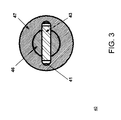
- FIG. 3 is a pictorial diagram illustrating one embodiment of a variable optical attenuator with lock pin in accordance with the present invention.
- FIG. 4 is a pictorial diagram illustrating another embodiment of a variable optical attenuator that hermetically sealed in accordance with the present invention.
- FIG. 5 is a flow diagram illustrating a process in adjusting the variable optical attenuator in accordance with the present invention.
- FIG. 1 is a pictorial diagram illustrating a variable optical attenuator 10 in accordance with the present invention.
- An incident light from a waveguide 11 is collimated by lens 13 and strikes on a reflector 14 .
- the reflected beam passes through the lens 13 and returns back to a waveguide 12 . If the reflector 14 is moved away from original focal position A to position A 2 , the incident beam into the reflector 14 will result the reflected beam lateral shift from a beam path b to a beam path b 2 . Thus, certain portion of the light cannot be returned back to the receiving waveguide 12 . Therefore, the optical power into the receiving waveguide 12 is attenuated.
- FIG. 2 is a pictorial diagram illustrating the cross-section of a variable optical attenuator device 20 .
- a dual-fiber collimator 21 is soldered on a main body 27 , while a moving screw 25 is mounted on an auxiliary body 28 .
- a reflective mirror 22 is mounted on a moving part 26 .
- the main body 27 and auxiliary body 28 are joined together over the solder area 29 .
- the moving part 26 When the screw 25 is screwed into the auxiliary body 28 at maximum extension, the moving part 26 is pushed toward the collimator 21 , and the spring 32 is fully compressed. The mirror position is located at the focal position of the dual-fiber collimator 21 . At this situation, the VOA is at minimal attenuation. With the screw 25 is screwed out of the auxiliary body 28 , the spring force pushes the moving part 26 away, and consequently, moves the reflective mirror 22 away from the focal position. Therefore, the attenuation is increased. Therefore, by adjusting the position of the screw 25 with respect to the auxiliary body 28 , the continuous attenuation is achieved. In order to maintain the continuous variation of the attenuation, the mirror 22 has to move without any tip and tilt error. Two locking pins 23 a and 23 b are mounted on the moving part 26 , and are positioned along the guide slots 33 a and 33 b.
- an O-ring 31 is mounted on the moving part 26 .
- This structure allows the en-longed path for blocking the moisture from entering the package.
- the movement of the screw 25 is not affected by is this hermetically seal O-ring 31 , and still able to freely adjust the position of the mirror 22 .
- the spring 32 also provides the forward stop position of the screw 25 to prevent the clashing of the reflector 22 into the collimator 21 .
- FIG. 3 is a pictorial diagram illustrating one embodiment 30 of a variable optical attenuator apparatus with a lock pin, representing the cross-section of A—A in FIG. 2 .
- An objective of the VOA 20 is that the movement of a moving part 46 does not introduced any tip and tilt errors, as these errors will cause the non-monotonous variation of the attenuation during the adjustment.
- One embodiment of the VOA 20 uses two lock pins 23 a and 23 b mounted on the moving part 26 , and the pins is guided by the two machined slots 33 a and 33 b on the main body 27 .
- FIG. 4 is a pictorial diagram illustrating another embodiment 40 of a variable optical attenuator that is hermetically sealed.
- the movement guide uses two sets of springs loaded balls assembled on the moving part 26 to replace the two sets of lock pins 23 a and 23 b shown in FIG. 2 .
- the spring force tightly contacts the two balls 41 a and 41 b with the two guide slots on the main body 27 .
- the advantage of using spring balls is to keep the tight contact of the guide slots, and the required machined tolerance of the guide slots 33 a and 33 b can also be reduced.
- FIG. 5 is a flow diagram illustrating a process 50 in adjusting the variable optical attenuator 20 .
- the amount of attenuation will either be adjusted to a lower attenuation or a higher attenuation.
- the screw 25 is turned inward 53 if the desirable result is to reduce 52 the amount of attenuation.
- the screw 25 is turned outward 55 if the desirable result is to increase 54 the amount of attenuation.
- the spring 32 and screw 25 maintain the attenuation value in place 56 .
Abstract
Description
Claims (21)
Priority Applications (1)
| Application Number | Priority Date | Filing Date | Title |
|---|---|---|---|
| US09/773,854 US6529673B1 (en) | 2001-01-31 | 2001-01-31 | Manual variable optical attenuator and method |
Applications Claiming Priority (1)
| Application Number | Priority Date | Filing Date | Title |
|---|---|---|---|
| US09/773,854 US6529673B1 (en) | 2001-01-31 | 2001-01-31 | Manual variable optical attenuator and method |
Publications (1)
| Publication Number | Publication Date |
|---|---|
| US6529673B1 true US6529673B1 (en) | 2003-03-04 |
Family
ID=25099523
Family Applications (1)
| Application Number | Title | Priority Date | Filing Date |
|---|---|---|---|
| US09/773,854 Expired - Lifetime US6529673B1 (en) | 2001-01-31 | 2001-01-31 | Manual variable optical attenuator and method |
Country Status (1)
| Country | Link |
|---|---|
| US (1) | US6529673B1 (en) |
Cited By (7)
| Publication number | Priority date | Publication date | Assignee | Title |
|---|---|---|---|---|
| US6684022B2 (en) * | 2001-08-29 | 2004-01-27 | Hon Hai Precision Ind. Co., Ltd. | Manual variable optical attenuator having sealing gasket |
| US20040037493A1 (en) * | 2002-08-23 | 2004-02-26 | Asia Pacific Microsystems, Inc. | Optical signal processing apparatus based on movable tilted reflection mirror |
| US20040096177A1 (en) * | 2002-11-15 | 2004-05-20 | Chang-Kyu Kim | Variable optical attenuator with tunable wavelength selectivity |
| US6904223B1 (en) * | 2003-04-04 | 2005-06-07 | Optiworks, Inc. | Tilted-translation variable optical attenuator |
| US7340125B1 (en) * | 2004-09-03 | 2008-03-04 | The Mind Institute | Optical switches and switching methods |
| US20080253731A1 (en) * | 2007-04-04 | 2008-10-16 | O-Net Communications (Shenzhen) Limited | Variable optical attenuator |
| CN104310301A (en) * | 2014-11-12 | 2015-01-28 | 深圳市盛喜路科技有限公司 | MEMS (micro-electromechanical systems) variable optical attenuator chip with integrated micro-gasket and manufacturing method of chip |
Citations (2)
| Publication number | Priority date | Publication date | Assignee | Title |
|---|---|---|---|---|
| US4516827A (en) | 1982-07-16 | 1985-05-14 | The United States Of America As Represented By The Secretary Of The Army | Variable optical attenuator |
| US6137941A (en) * | 1998-09-03 | 2000-10-24 | Lucent Technologies, Inc. | Variable optical attenuator |
-
2001
- 2001-01-31 US US09/773,854 patent/US6529673B1/en not_active Expired - Lifetime
Patent Citations (2)
| Publication number | Priority date | Publication date | Assignee | Title |
|---|---|---|---|---|
| US4516827A (en) | 1982-07-16 | 1985-05-14 | The United States Of America As Represented By The Secretary Of The Army | Variable optical attenuator |
| US6137941A (en) * | 1998-09-03 | 2000-10-24 | Lucent Technologies, Inc. | Variable optical attenuator |
Cited By (11)
| Publication number | Priority date | Publication date | Assignee | Title |
|---|---|---|---|---|
| US6684022B2 (en) * | 2001-08-29 | 2004-01-27 | Hon Hai Precision Ind. Co., Ltd. | Manual variable optical attenuator having sealing gasket |
| US20040037493A1 (en) * | 2002-08-23 | 2004-02-26 | Asia Pacific Microsystems, Inc. | Optical signal processing apparatus based on movable tilted reflection mirror |
| US20040096177A1 (en) * | 2002-11-15 | 2004-05-20 | Chang-Kyu Kim | Variable optical attenuator with tunable wavelength selectivity |
| US20050191025A1 (en) * | 2002-11-15 | 2005-09-01 | Electronics And Telecommunications Research Institute | Variable optical attenuator with tunable wavelength selectivity |
| US6947656B2 (en) * | 2002-11-15 | 2005-09-20 | Electronics And Telecommunications Research Institute | Variable optical attenuator with tunable wavelength selectivity |
| US6904223B1 (en) * | 2003-04-04 | 2005-06-07 | Optiworks, Inc. | Tilted-translation variable optical attenuator |
| US7340125B1 (en) * | 2004-09-03 | 2008-03-04 | The Mind Institute | Optical switches and switching methods |
| US20080253731A1 (en) * | 2007-04-04 | 2008-10-16 | O-Net Communications (Shenzhen) Limited | Variable optical attenuator |
| US7522808B2 (en) * | 2007-04-04 | 2009-04-21 | O-Net Communications (Shenzhen) Limited | Variable optical attenuator |
| CN104310301A (en) * | 2014-11-12 | 2015-01-28 | 深圳市盛喜路科技有限公司 | MEMS (micro-electromechanical systems) variable optical attenuator chip with integrated micro-gasket and manufacturing method of chip |
| CN104310301B (en) * | 2014-11-12 | 2023-08-08 | 苏州盛维新电子科技有限公司 | MEMS adjustable optical attenuator chip integrated with micro-pad and manufacturing method thereof |
Similar Documents
| Publication | Publication Date | Title |
|---|---|---|
| US7019883B2 (en) | Dynamic optical filter having a spatial light modulator | |
| US6307657B1 (en) | Optomechanical platform | |
| US5018816A (en) | Optical delay switch and variable delay system | |
| US6222656B1 (en) | Fiber optics signal attenuator | |
| US7295748B2 (en) | Variable optical attenuator with wavelength dependent loss compensation | |
| US6718114B2 (en) | Variable optical attenuator of optical path conversion | |
| JP2786322B2 (en) | Reflection reduction assembly | |
| US6149278A (en) | Wavelength independent variable optical attenuator | |
| US6529673B1 (en) | Manual variable optical attenuator and method | |
| US10182275B1 (en) | Passive optical subassembly with a signal pitch router | |
| US6915061B2 (en) | Variable optical attenuator with MEMS devices | |
| US20020097977A1 (en) | Variable optical attenuator | |
| US6751374B2 (en) | Light-signal delaying device | |
| US20050041973A1 (en) | Optical component provided with demultiplexing function and wavelength dispersion compensator | |
| EP2083298B1 (en) | Optical device comprising a compact dispersing system | |
| US6374032B1 (en) | Variable optical attenuator | |
| US6253005B1 (en) | Apparatus and method for compensating for misalignment in reflective packages | |
| US6614958B1 (en) | Optical imaging system | |
| US20050031256A1 (en) | Temperature compensation method of an optical wdm component and temperature-compensated optical wdm component | |
| US6904223B1 (en) | Tilted-translation variable optical attenuator | |
| US6600762B2 (en) | Wavelength-variable light source, and optical component loss measuring device | |
| US6665485B2 (en) | Variable optical attenuator | |
| US20020176685A1 (en) | Variable optical attenuator | |
| US6633721B2 (en) | Variable optical attenuator | |
| US20030091318A1 (en) | Dual fiber variable optical attenuator |
Legal Events
| Date | Code | Title | Description |
|---|---|---|---|
| AS | Assignment |
Owner name: AVANEX CORPORATION, CALIFORNIA Free format text: ASSIGNMENT OF ASSIGNORS INTEREST;ASSIGNORS:LIU, YONGSHENG;NGUYEN, VINCENT;REEL/FRAME:011513/0363 Effective date: 20010131 |
|
| STCF | Information on status: patent grant |
Free format text: PATENTED CASE |
|
| REMI | Maintenance fee reminder mailed | ||
| FPAY | Fee payment |
Year of fee payment: 4 |
|
| SULP | Surcharge for late payment | ||
| FEPP | Fee payment procedure |
Free format text: PAYOR NUMBER ASSIGNED (ORIGINAL EVENT CODE: ASPN); ENTITY STATUS OF PATENT OWNER: LARGE ENTITY |
|
| FPAY | Fee payment |
Year of fee payment: 8 |
|
| AS | Assignment |
Owner name: WELLS FARGO CAPITAL FINANCE, INC., AS AGENT, CALIF Free format text: PATENT SECURITY AGREEMENT;ASSIGNOR:OCLARO (NORTH AMERICA), INC.;REEL/FRAME:028487/0373 Effective date: 20110726 |
|
| AS | Assignment |
Owner name: OCLARO (NORTH AMERICA), INC., CALIFORNIA Free format text: ASSIGNMENT OF ASSIGNORS INTEREST;ASSIGNOR:AVANEX CORPORATION;REEL/FRAME:032494/0343 Effective date: 20090707 |
|
| AS | Assignment |
Owner name: II-VI INCORPORATED, PENNSYLVANIA Free format text: ASSIGNMENT OF ASSIGNORS INTEREST;ASSIGNORS:OCLARO TECHNOLOGY LIMITED;OCLARO, INC.;OCLARO (NORTH AMERICA), INC.;AND OTHERS;REEL/FRAME:032554/0818 Effective date: 20131101 |
|
| AS | Assignment |
Owner name: OCLARO TECHNOLOGY LIMITED, CALIFORNIA Free format text: RELEASE OF SECURITY INTEREST;ASSIGNOR:WELLS FARGO CAPITAL FINANCE, LLC;REEL/FRAME:032982/0222 Effective date: 20131101 Owner name: OCLARO, INC., CALIFORNIA Free format text: RELEASE OF SECURITY INTEREST;ASSIGNOR:WELLS FARGO CAPITAL FINANCE, LLC;REEL/FRAME:032982/0222 Effective date: 20131101 |
|
| FPAY | Fee payment |
Year of fee payment: 12 |
|
| AS | Assignment |
Owner name: BANK OF AMERICA, N.A., AS ADMINISTRATIVE AGENT, NO Free format text: NOTICE OF GRANT OF SECURITY INTEREST IN PATENTS;ASSIGNORS:II-VI INCORPORATED;MARLOW INDUSTRIES, INC.;EPIWORKS, INC.;AND OTHERS;REEL/FRAME:050484/0204 Effective date: 20190924 Owner name: BANK OF AMERICA, N.A., AS ADMINISTRATIVE AGENT, NORTH CAROLINA Free format text: NOTICE OF GRANT OF SECURITY INTEREST IN PATENTS;ASSIGNORS:II-VI INCORPORATED;MARLOW INDUSTRIES, INC.;EPIWORKS, INC.;AND OTHERS;REEL/FRAME:050484/0204 Effective date: 20190924 |
|
| AS | Assignment |
Owner name: II-VI DELAWARE, INC., DELAWARE Free format text: ASSIGNMENT OF ASSIGNORS INTEREST;ASSIGNOR:II-VI INCORPORATED;REEL/FRAME:051210/0411 Effective date: 20191202 |
|
| AS | Assignment |
Owner name: PHOTOP TECHNOLOGIES, INC., CALIFORNIA Free format text: PATENT RELEASE AND REASSIGNMENT;ASSIGNOR:BANK OF AMERICA, N.A., AS ADMINISTRATIVE AGENT;REEL/FRAME:060574/0001 Effective date: 20220701 Owner name: II-VI OPTOELECTRONIC DEVICES, INC., NEW JERSEY Free format text: PATENT RELEASE AND REASSIGNMENT;ASSIGNOR:BANK OF AMERICA, N.A., AS ADMINISTRATIVE AGENT;REEL/FRAME:060574/0001 Effective date: 20220701 Owner name: II-VI DELAWARE, INC., PENNSYLVANIA Free format text: PATENT RELEASE AND REASSIGNMENT;ASSIGNOR:BANK OF AMERICA, N.A., AS ADMINISTRATIVE AGENT;REEL/FRAME:060574/0001 Effective date: 20220701 Owner name: II-VI PHOTONICS (US), INC., MASSACHUSETTS Free format text: PATENT RELEASE AND REASSIGNMENT;ASSIGNOR:BANK OF AMERICA, N.A., AS ADMINISTRATIVE AGENT;REEL/FRAME:060574/0001 Effective date: 20220701 Owner name: M CUBED TECHNOLOGIES, INC., CONNECTICUT Free format text: PATENT RELEASE AND REASSIGNMENT;ASSIGNOR:BANK OF AMERICA, N.A., AS ADMINISTRATIVE AGENT;REEL/FRAME:060574/0001 Effective date: 20220701 Owner name: II-VI OPTICAL SYSTEMS, INC., CALIFORNIA Free format text: PATENT RELEASE AND REASSIGNMENT;ASSIGNOR:BANK OF AMERICA, N.A., AS ADMINISTRATIVE AGENT;REEL/FRAME:060574/0001 Effective date: 20220701 Owner name: FINISAR CORPORATION, CALIFORNIA Free format text: PATENT RELEASE AND REASSIGNMENT;ASSIGNOR:BANK OF AMERICA, N.A., AS ADMINISTRATIVE AGENT;REEL/FRAME:060574/0001 Effective date: 20220701 Owner name: OPTIUM CORPORATION, CALIFORNIA Free format text: PATENT RELEASE AND REASSIGNMENT;ASSIGNOR:BANK OF AMERICA, N.A., AS ADMINISTRATIVE AGENT;REEL/FRAME:060574/0001 Effective date: 20220701 Owner name: COADNA PHOTONICS, INC., PENNSYLVANIA Free format text: PATENT RELEASE AND REASSIGNMENT;ASSIGNOR:BANK OF AMERICA, N.A., AS ADMINISTRATIVE AGENT;REEL/FRAME:060574/0001 Effective date: 20220701 Owner name: KAILIGHT PHOTONICS, INC., CALIFORNIA Free format text: PATENT RELEASE AND REASSIGNMENT;ASSIGNOR:BANK OF AMERICA, N.A., AS ADMINISTRATIVE AGENT;REEL/FRAME:060574/0001 Effective date: 20220701 Owner name: LIGHTSMYTH TECHNOLOGIES, INC., OREGON Free format text: PATENT RELEASE AND REASSIGNMENT;ASSIGNOR:BANK OF AMERICA, N.A., AS ADMINISTRATIVE AGENT;REEL/FRAME:060574/0001 Effective date: 20220701 Owner name: EPIWORKS, INC., ILLINOIS Free format text: PATENT RELEASE AND REASSIGNMENT;ASSIGNOR:BANK OF AMERICA, N.A., AS ADMINISTRATIVE AGENT;REEL/FRAME:060574/0001 Effective date: 20220701 Owner name: MARLOW INDUSTRIES, INC., TEXAS Free format text: PATENT RELEASE AND REASSIGNMENT;ASSIGNOR:BANK OF AMERICA, N.A., AS ADMINISTRATIVE AGENT;REEL/FRAME:060574/0001 Effective date: 20220701 Owner name: II-VI INCORPORATED, PENNSYLVANIA Free format text: PATENT RELEASE AND REASSIGNMENT;ASSIGNOR:BANK OF AMERICA, N.A., AS ADMINISTRATIVE AGENT;REEL/FRAME:060574/0001 Effective date: 20220701 |