US6529010B1 - Location of fault on series-compensated power transmission lines - Google Patents

Location of fault on series-compensated power transmission lines Download PDF

Info

Publication number
US6529010B1
US6529010B1 US09/582,087 US58208700A US6529010B1 US 6529010 B1 US6529010 B1 US 6529010B1 US 58208700 A US58208700 A US 58208700A US 6529010 B1 US6529010 B1 US 6529010B1
Authority
US
United States
Prior art keywords
fault
post
distance
transmission line
power transmission
Prior art date
Legal status (The legal status is an assumption and is not a legal conclusion. Google has not performed a legal analysis and makes no representation as to the accuracy of the status listed.)
Expired - Lifetime
Application number
US09/582,087
Inventor
Murari Saha
Jan Izykowski
Eugeniusz Rosolowski
Bogdan Kasztenny
Current Assignee (The listed assignees may be inaccurate. Google has not performed a legal analysis and makes no representation or warranty as to the accuracy of the list.)
Hitachi Energy Switzerland AG
Original Assignee
ABB AB
Priority date (The priority date is an assumption and is not a legal conclusion. Google has not performed a legal analysis and makes no representation as to the accuracy of the date listed.)
Filing date
Publication date
Application filed by ABB AB filed Critical ABB AB
Assigned to ABB AB reassignment ABB AB ASSIGNMENT OF ASSIGNORS INTEREST (SEE DOCUMENT FOR DETAILS). Assignors: SAHA, MURARI, IZYKOWSKI, JAN, KASZTENNY, BOGDAN, ROSOLOWSKI, EUGENIUSZ
Application granted granted Critical
Publication of US6529010B1 publication Critical patent/US6529010B1/en
Anticipated expiration legal-status Critical
Assigned to ABB POWER GRIDS SWITZERLAND AG reassignment ABB POWER GRIDS SWITZERLAND AG ASSIGNMENT OF ASSIGNORS INTEREST (SEE DOCUMENT FOR DETAILS). Assignors: ABB SCHWEIZ AG
Expired - Lifetime legal-status Critical Current

Links

Images

Classifications

    • GPHYSICS
    • G01MEASURING; TESTING
    • G01RMEASURING ELECTRIC VARIABLES; MEASURING MAGNETIC VARIABLES
    • G01R31/00Arrangements for testing electric properties; Arrangements for locating electric faults; Arrangements for electrical testing characterised by what is being tested not provided for elsewhere
    • G01R31/08Locating faults in cables, transmission lines, or networks
    • G01R31/081Locating faults in cables, transmission lines, or networks according to type of conductors
    • G01R31/085Locating faults in cables, transmission lines, or networks according to type of conductors in power transmission or distribution lines, e.g. overhead

Definitions

  • the present invention forms an integral part of a protection system for power transmission lines which are series-compensated with capacitors. Specifically, the invention relates to a method and a device for locating a fault which has occurred on the power transmission line. The distance from a station, located at one end of the power transmission line, to the fault is determined with the aid of calculating algorithms based on impedance models of the power transmission line and voltages and currents measured at the station before and after the occurrence of the fault.
  • a method for fault location on a three-phase power transmission line is known from U.S. Pat. No. 4,559,491.
  • the method for fault location on a three-phase power transmission line, described in U.S. Pat. No. 4,559,491 is based on an impedance model of the power transmission line.
  • a condition for the method according to U.S. Pat. No. 4,559,491 is that the power transmission line has a linear impedance also when a fault has occurred.
  • Series capacitors for phase compensation are normally provided with overvoltage protection devices in the form of some protection component with a non-linear characteristic in the area of interference and the method according to U.S. Pat. No. 4,559,491 is therefore not applicable to a three-phase power transmission line with series capacitors for phase compensation.
  • fault location on a three-phase power transmission line may be made according to method based on a waveguide model of the power transmission line.
  • Fault location on a power transmission line with series capacitors for phase compensation based on a waveguide model of the power transmission line may, for certain types of faults, give a misleading result and this fault-location technique has therefore not been accepted by the users.
  • a method for fault location based on an impedance model of the power transmission line should take into consideration the fact that the occurrence of a fault on the monitored power transmission line entails the feeding of electric power from both ends of the power transmission line to the site of the fault in question since otherwise the fault location cannot be performed with sufficient accuracy.
  • fault location based on an impedance model of the power transmission line assumes that the power inputs from the two ends of the power transmission line are determined by measuring or calculating the two power inputs. From U.S. Pat. No. 5,455,776 it is known that fault location on a three-phase transmission line may be made with a method which assumes measurement of voltage and current at the two ends of the monitored transmission line.
  • the method could be adapted to series-compensated transmission lines but has the disadvantage of being dependent on measured values from the two ends of the transmission line, which complicates the fault location and makes it more expensive compared with methods operating with measured values from one end of the transmission line only, normally the end of the transmission line where the fault location is arranged.
  • FIG. 1 shows an impedance model of a faultless power transmission line, series-compensated with capacitors with overvoltage protection device, between two stations A and B.
  • FIG. 2 shows an impedance model of the same power transmission line when a fault has occurred between the series capacitors and station B.
  • FIG. 3 shows an impedance model of the same power transmission line when a fault has occurred between station A and the series capacitors.
  • FIG. 4 shows possible fault configurations on the power transmission line.
  • FIGS. 5 and 6 show how the parallel connection of the series capacitors and the overvoltage protection device may be replaced by a model-equivalent impedance consisting of a series connection of a resistance and a reactance.
  • FIG. 7 shows how the parameters of the model equivalent as a function of a current, passing through the impedance, may be determined.
  • FIG. 8 shows how a device for carrying out the method may be designed.
  • FIG. 1 A single-line diagram for a faultless power transmission line, series-compensated with capacitors, between two stations A and B is shown in FIG. 1 .
  • the terms “backward” and “forward” are often used when referring to the location of a power network in relation to the power transmission line.
  • a backward power network according to FIG. 1 is represented by an emf E A and an impedance Z A .
  • a forward network is represented by an emf E B and an impedance Z B .
  • FIG. 1 shows
  • the capacitors in series-compensated power networks are normally provided with a parallel-connected overvoltage protection device.
  • the parallel connection will be referred to below as “SC&OVP” and is represented by a non-linear impedance because of the non-linear current/voltage characteristic of the overvoltage protection device.
  • (1-d)dZ L the impedance of the power transmission line between SC&OVP and station B.
  • the faultless power transmission line that is, prior to the occurrence of a fault, may thus, according to FIG. 1, be described, in matrix form, by the equation
  • the index “pre” implies that the value of the quantity in question is the value prior to the occurrence of a fault.
  • equations with quantities with the index “post” will also be described, which, in a corresponding manner, implies that the value of the quantity in question is the value after the occurrence of a fault.
  • a condition for the distance-to-fault calculation is thus that a continuous measurement and storage of a number of consecutively measured voltage and current values is performed.
  • FIG. 2 shows an impedance model of a series-compensated power transmission line when a fault has occurred between SC&OVP and station B.
  • a fault which has occurred within this area will be referred to below as a fault 1 .
  • the impedance model according to FIG. 2 may, in matrix form, be described with the equation
  • E A ⁇ E B [Z A +x 1 Z L +Z SC — post ]I A — post ⁇ [(1 ⁇ x 1 ) Z L +Z B ]I B — post (2)
  • x 1 designates the distance from the end point A of the monitored power transmission line to the fault.
  • FIG. 3 shows an impedance model and a series-compensated power transmission line when a fault has occurred between station A and SC&OVP.
  • a fault which has occurred within this area will be referred to below as a fault 2 .
  • the impedance model according to FIG. 3 may, in matrix form, be described with the equation
  • E A ⁇ E B [Z A +x 2 Z L ]I A — post ⁇ [(1 ⁇ x 2 ) Z L +Z B +Z SC — post ]I B — post (3)
  • the fault is represented by a fault resistance R f to ground or zero.
  • a fault on a three-phase line R, S and T may occur in a plurality of different ways.
  • FIG. 4 shows how a fault with a fault resistance R R , R S and R T may occur between any of the phases and ground and as R RS , R ST etc. between different phases. A combination of the individual cases may also occur.
  • the voltage at the fault site is defined as V fR , V fS and V fT and the corresponding currents as I fR , I fS and I fT.
  • K f The elements in K f are determined in dependence on the type of fault as follows:
  • non-diagonal elements are given the value 0 if the phase in question is not concerned by the relevant fault and the value ⁇ 1 if the phase is concerned by the relevant fault
  • the diagonal elements are given the value 1 if the phase in question has a fault to ground at the fault in question and to this is added the sum of the absolute values of the non-diagonal elements in the relevant line.
  • K f [ 1 0 0 0 0 0 0 0 0 0 ⁇ ] ⁇ ⁇ for ⁇ ⁇ fault ⁇ ⁇ R ⁇ - ⁇ ground
  • K f [ ⁇ 2 - 1 - 1 - 1 2 - 1 - 1 - 1 2 ⁇ ] ⁇ ⁇ for ⁇ ⁇ fault ⁇ ⁇ R ⁇ - ⁇ S ⁇ - ⁇ T ⁇
  • K f [ ⁇ 3 - 1 - 1 - 1 3 - 1 - 1 - 1 3 ⁇ ] ⁇ ⁇ for ⁇ ⁇ fault ⁇ ⁇ R ⁇ - ⁇ S ⁇ - ⁇ T ⁇ - ⁇ ground
  • Z SC the value of the non-linear impedance as a function of the actual current flowing through the impedance.
  • One way of determining Z SC is to transform the parallel connection according to FIG. 5 into a model-equivalent impedance according to FIG. 6 in the form of a series connection of a resistance R SC and a reactance X SC .
  • R SC and X SC may be determined individually as functions of a traversing current I SC , according to FIG. 7, or in the form of a corresponding analytic function. This implies that, when the current through Z SC is known, Z SC may be determined as
  • both R SC and X SC i.e. Z SC , can be determined with the current I A measured in station A.
  • I B ((1 ⁇ x 2 ) Z L +Z B +Z SC ) ⁇ 1 .(( Z A +x 2 Z L ) I A ⁇ ( E A ⁇ E B )) (6)
  • the value of I B thus obtained determines, in its turn, a preliminary value of Z SC in the same way as above and will be used in the calculating algorithm which will be described below for the distance-to-fault calculation.
  • the calculating algorithms according to the invention which calculate the distances from station A to the fault are based on the impedance models related above and corresponding equations in matrix form. Since the impedance models are different depending on whether the fault is located between SC&OVP and station B or between station A and SC&OVP, also the calculating algorithms will be different.
  • the calculating algorithm for calculating a fault 1 that is, calculating the distance from station A to a fault which is located between SC&OVP and station B, consists of the equations
  • E A ⁇ E B [Z A +x 1 Z L +Z SC — post ]I A — post ⁇ [(1 ⁇ x 1 ) Z L +Z B ]I B — post (2)
  • V A — post ⁇ V f ( x 1 Z L +Z SC — post ) I A — post (7)
  • D 1 T which designates the transpose matrix of D 1
  • a _ 1 D 1 T D 1 T ⁇ D 1 ⁇ Z L ⁇ K f ⁇ Z L ⁇ I A_post ( 11 )
  • b _ 1 D 1 T D 1 T ⁇ D 1 ⁇ ⁇ ( Z L ⁇ K f ⁇ [ V A_post + ( Z L - Z SC_post ) ⁇ I A_post ] + Z B ⁇ K f ⁇ Z L ⁇ I A_post ) ( 12 )
  • c _ 1 D 1 T D 1 T ⁇ D 1 ⁇ ( Z L + Z B ) ⁇ ( V A_post - Z SC_post ⁇ I A_post ) ⁇ K f ( 13 )
  • Im(a 1 ), Im(b 1 ) och Im(c 1 ) are equal to the imaginary part of the coefficients.
  • Re(a 1 ), Re(b 1 ) and Re(c 1 ) are equal to the real part of the coefficients.
  • Determination of distance to fault and fault resistance is made by an iterative process which will be described below.
  • the calculating algorithm for the distance-to-fault calculation in case of fault 2 consists of the following equation system:
  • E A ⁇ E B [Z A +x 2 Z L ]I A — post ⁇ [(1 ⁇ x 2 ) Z L +Z B +Z SC — post ]I B — post (3)
  • V A — post ⁇ V 1 x 2 Z L I A — post (16)
  • a _ 2 D 2 T D 2 T ⁇ D 2 ⁇ Z L ⁇ K f ⁇ Z L ⁇ I A_post ( 20 )
  • b _ 2 D 2 T D 2 T ⁇ D 2 ⁇ ⁇ ( Z L ⁇ K f ⁇ V A_post + [ Z L + Z SC_post + Z B ] ⁇ K f ⁇ Z L ⁇ I A_post ) ( 21 )
  • c _ 2 D 2 T D 2 T ⁇ D 2 ⁇ ( Z L + Z B + Z SC_post ) ⁇ K f ⁇ V A_post ( 22 )
  • R f2 Re ( a 2 ) x 21 2 ⁇ Re ( b 2 ) x 21 +Re ( c 2 ) (24)
  • Determination of distance to fault and fault resistance is made by an iterative process which will be described below.
  • the type of fault and hence also the K f matrix may be determined.
  • R SC and X SC are determined, for example with FIG. 7, whereupon Z SC in equation (2) may be determined.
  • the first calculated value of the distance to the fault is compared with the assumed value of the distance to the fault. If the difference between the values is greater than a pre-set maximally permissible difference value S 1 , the assumed value in equations (2) and (7) is replaced by the first calculated value of the distance to the fault and the fault resistance.
  • a preliminary value of the current through Z SC is calculated by means of equation (5).
  • a first value of R SC and X SC that is also Z SC , may be obtained.
  • the first calculated values are compared with the assumed value of Z SC . If the difference between the values is greater than a preset maximally permissible difference value S 2 , the set value in equation (6) is replaced by the first calculated value of Z SC . This iteration continues until the difference value of two consecutive calculation procedures is smaller than the set maximally permissible difference value, whereupon the last calculated value of Z SC constitutes the assumption of Z SC which is needed in equations (3) and (16).
  • the first calculated value of the distance to the fault is compared with the set value of the distance to the fault. If the difference between the values is greater than a pre-set maximally permissible difference value S 3 , the set value in equations (3) and (16) is replaced by the first calculated value of the distance to the fault and the fault resistance.
  • a method for determining which of the distance-to-fault values represents the actual distance to the fault is different depending on whether the fault is a three-phase fault or if it is an unsymmetrical fault, that is, if one or more phases is/are faultless.
  • the fault is a fault 2 and it is asked whether R f2 >R 0 ? where R 0 is a preset minimum value. If the answer is yes, the fault is a fault 2 , that is, the calculated value of x 21 is the true value of the distance to the fault. If the answer is no, it is a fault 1 , that is, the calculated value of x 11 is the true value of the distance to the fault.
  • the fault is a fault 1 and it is asked whether R f1 >R 0 ? where R 0 is a preset minimum value. If the answer is yes, the fault is a fault 1 , that is, the calculated value of x 1 is the true value of the distance to the fault. If the answer is no, it is a fault 2 , that is, the calculated value of x 21 is the true value of the distance to the fault.
  • the currents through the fault resistances must first be determined for the two cases of fault.
  • phase currents through the fault resistance may be determined with the aid of
  • i f(R,S,T)1 i A(R,S,T) +i B(R,S,T)1 (25)
  • phase currents through the fault resistance may be determined with the aid of
  • the method for determining whether it is a question of a fault 1 or a fault 2 comprises, after a faultless phase has been identified in conventional manner, first determining the currents at the site of the fault in the faultless phase or phases for the two cases of fault according to equations (25), (2) and (26), (3), that is i ff1 och i ff2 . Then follows the following procedure:
  • the continued determination procedure is exactly identical with the procedure when the fault is a three-phase fault, that is: In case of a fault 2 , it is asked whether R f2 >R 0 ? where R 0 is a preset minimum value. If the answer is yes, the fault is a fault 2 , that is, the calculated value of x 21 is the true value of the distance to the fault. If the answer is no, it is a fault 1 , that is, the calculated value of x 11 is the true value of the distance to the fault.
  • a fault 1 it is asked whether R f1 >R 0 ? where R 0 is a preset minimum value. If the answer is yes, the fault is a fault 1 , that is, the calculated value of x 11 is the true value of the distance to the fault. If the answer is no, it is a fault 2 , that is, the calculated value of x 21 is the true value of the distance to the fault.
  • a device for determining the distance from a station, at one end of a transmission line, until the occurrence of a fault on the transmission line according to the described method comprises certain measuring devices, measurement value converters, members for iterative treatment of the calculating algorithms of the method, a possibility of inputting to the member known conditions regarding the parameters of the power networks and assumed values of distance to fault, fault resistance, etc., a VDU indicating the calculated distance to fault, and a printer for printout of the calculated distance to fault.
  • FIG. 8 largely shows an embodiment of the device. Embodiments similar to those of FIG. 8 are within the scope of the invention.
  • FIG. 8 shows a transmission line 1 between two stations A and B.
  • the line is provided with capacitors, protecting against overvoltages, forming the impedance Z SC .
  • Station A accommodates measuring devices 2 and 3 for continuous measurement of all the phase currents and phase voltages.
  • a number of these consecutively measured values which in case of a fault are passed to a calculating unit 6 , are filtered and stored.
  • the calculating unit is provided with the calculating algorithms described, programmed for the iterative processes which are needed for calculating the distance to fault and the fault resistance.
  • the calculating unit was provided with a number of conditions and assumptions to be able to perform the calculation of the distance to fault etc. These conditions comprise values of the emf and the impedance of both a forward and a backward power network.
  • the calculating unit is also supplied with known values of the length and impedance of the transmission line, the distance from station A to the series capacitors, set values of the distance to fault, the fault resistance, Z SC and the maximally permissible difference values S 1 , S 2 and S 3 .
  • information about the type of fault may be supplied to the calculating unit for determining the fault-type matrix K f .
  • the calculating procedure starts with the necessary iterations to obtain difference values which fall below the maximally permissible ones.
  • the finally calculated values will then be transferred to a VDU which shows the distance to the fault and the magnitude of the fault resistance, respectively, for further actions.
  • the device also comprises possibilities for printout of the result.
  • parts of the embodiment according to FIG. 8 may be more or less integrated in the calculating unit.

Abstract

The present invention relates to a method for locating a fault on a power transmission line which is series-compensated with capacitors. The site of the fault is determined with the aid of measured currents and voltages at one of the two ends of the power transmission line before and after the occurrence of the fault and a calculating algorithm based on impedance models of the power transmission line before and after the occurrence of the fault.

Description

TECHNICAL FIELD
The present invention forms an integral part of a protection system for power transmission lines which are series-compensated with capacitors. Specifically, the invention relates to a method and a device for locating a fault which has occurred on the power transmission line. The distance from a station, located at one end of the power transmission line, to the fault is determined with the aid of calculating algorithms based on impedance models of the power transmission line and voltages and currents measured at the station before and after the occurrence of the fault.
BACKGROUND ART, PROBLEMS
A method for fault location on a three-phase power transmission line is known from U.S. Pat. No. 4,559,491. The method for fault location on a three-phase power transmission line, described in U.S. Pat. No. 4,559,491, is based on an impedance model of the power transmission line. A condition for the method according to U.S. Pat. No. 4,559,491 is that the power transmission line has a linear impedance also when a fault has occurred. Series capacitors for phase compensation are normally provided with overvoltage protection devices in the form of some protection component with a non-linear characteristic in the area of interference and the method according to U.S. Pat. No. 4,559,491 is therefore not applicable to a three-phase power transmission line with series capacitors for phase compensation.
From U.S. Pat. No. 4,719,580 it is known that fault location on a three-phase power transmission line may be made according to method based on a waveguide model of the power transmission line. Fault location on a power transmission line with series capacitors for phase compensation based on a waveguide model of the power transmission line may, for certain types of faults, give a misleading result and this fault-location technique has therefore not been accepted by the users.
A method for fault location based on an impedance model of the power transmission line should take into consideration the fact that the occurrence of a fault on the monitored power transmission line entails the feeding of electric power from both ends of the power transmission line to the site of the fault in question since otherwise the fault location cannot be performed with sufficient accuracy. To obtain a result with satisfactory accuracy in the fault-position determination, fault location based on an impedance model of the power transmission line assumes that the power inputs from the two ends of the power transmission line are determined by measuring or calculating the two power inputs. From U.S. Pat. No. 5,455,776 it is known that fault location on a three-phase transmission line may be made with a method which assumes measurement of voltage and current at the two ends of the monitored transmission line. The method could be adapted to series-compensated transmission lines but has the disadvantage of being dependent on measured values from the two ends of the transmission line, which complicates the fault location and makes it more expensive compared with methods operating with measured values from one end of the transmission line only, normally the end of the transmission line where the fault location is arranged.
A method for fault location based on measurement at one end of the transmission line only is described in IEEE Transaction on Power Apparatus and Systems, Vol. PAS-104, No. 2, February 1985, pp. 424-436. This method assumes that the monitored part of the transmission line is described by a linear model and the method is thus not useful for series-compensated transmission lines with non-linear protection devices for protecting the capacitors against overvoltage.
BRIEF DESCRIPTION OF THE DRAWINGS
FIG. 1 shows an impedance model of a faultless power transmission line, series-compensated with capacitors with overvoltage protection device, between two stations A and B.
FIG. 2 shows an impedance model of the same power transmission line when a fault has occurred between the series capacitors and station B.
FIG. 3 shows an impedance model of the same power transmission line when a fault has occurred between station A and the series capacitors.
FIG. 4 shows possible fault configurations on the power transmission line.
FIGS. 5 and 6 show how the parallel connection of the series capacitors and the overvoltage protection device may be replaced by a model-equivalent impedance consisting of a series connection of a resistance and a reactance.
FIG. 7 shows how the parameters of the model equivalent as a function of a current, passing through the impedance, may be determined.
FIG. 8 shows how a device for carrying out the method may be designed.
SUMMARY OF THE INVENTION, ADVANTAGES
A single-line diagram for a faultless power transmission line, series-compensated with capacitors, between two stations A and B is shown in FIG. 1. In this context, the terms “backward” and “forward” are often used when referring to the location of a power network in relation to the power transmission line. A backward power network according to FIG. 1 is represented by an emf EA and an impedance ZA. In a corresponding way, a forward network is represented by an emf EB and an impedance ZB. Further, FIG. 1 shows
ZL the impedance of the power transmission line
d the distance in per unit from station A to the series capacitors
dZL the impedance of the power transmission line between station A and the series-compensated capacitors.
The capacitors in series-compensated power networks are normally provided with a parallel-connected overvoltage protection device. The parallel connection will be referred to below as “SC&OVP” and is represented by a non-linear impedance because of the non-linear current/voltage characteristic of the overvoltage protection device.
ZSC non-linear impedance consisting of the series capacitors and their overvoltage protection devices
(1-d)dZL the impedance of the power transmission line between SC&OVP and station B.
The faultless power transmission line, that is, prior to the occurrence of a fault, may thus, according to FIG. 1, be described, in matrix form, by the equation
E A −E B =[Z A +Z B +Z L +Z SC pre ]I A pre  (1)
The index “pre” implies that the value of the quantity in question is the value prior to the occurrence of a fault. In the following description, equations with quantities with the index “post” will also be described, which, in a corresponding manner, implies that the value of the quantity in question is the value after the occurrence of a fault. A condition for the distance-to-fault calculation is thus that a continuous measurement and storage of a number of consecutively measured voltage and current values is performed.
As regards the post-fault situation, it must be distinguished whether the fault is located between station A and SC&OVP or if the fault is located between SC&OVP and station B.
FIG. 2 shows an impedance model of a series-compensated power transmission line when a fault has occurred between SC&OVP and station B. A fault which has occurred within this area will be referred to below as a fault 1. The impedance model according to FIG. 2 may, in matrix form, be described with the equation
E A −E B =[Z A +x 1 Z L +Z SC post ]I A post−[(1−x 1)Z L +Z B ]I B post  (2)
where x1 designates the distance from the end point A of the monitored power transmission line to the fault.
FIG. 3 shows an impedance model and a series-compensated power transmission line when a fault has occurred between station A and SC&OVP. A fault which has occurred within this area will be referred to below as a fault 2. The impedance model according to FIG. 3 may, in matrix form, be described with the equation
E A −E B =[Z A +x 2 Z L ]I A post−[(1−x 2)Z L +Z B +Z SC post ]I B post  (3)
In FIGS. 2 and 3, the fault is represented by a fault resistance Rf to ground or zero. A fault on a three-phase line R, S and T may occur in a plurality of different ways. FIG. 4 shows how a fault with a fault resistance RR, RS and RT may occur between any of the phases and ground and as RRS, RST etc. between different phases. A combination of the individual cases may also occur. The voltage at the fault site is defined as VfR, VfS and VfT and the corresponding currents as IfR, IfS and IfT.
To be able to distinguish the different types of fault that may occur, the distance-to-fault calculation makes use of a fault-type matrix which has the general form K f = [ k RR k SR k TR k RS k SS k TS k RT k ST k TT ]
Figure US06529010-20030304-M00001
The elements in Kf are determined in dependence on the type of fault as follows:
non-diagonal elements are given the value 0 if the phase in question is not concerned by the relevant fault and the value −1 if the phase is concerned by the relevant fault
The diagonal elements are given the value 1 if the phase in question has a fault to ground at the fault in question and to this is added the sum of the absolute values of the non-diagonal elements in the relevant line.
A few examples of a filled-in matrix Kf for some typical types of fault are shown below K f = [ 1 0 0 0 0 0 0 0 0 ] for fault R - ground K f = [ 2 - 1 - 1 - 1 2 - 1 - 1 - 1 2 ] for fault R - S - T K f = [ 3 - 1 - 1 - 1 3 - 1 - 1 - 1 3 ] for fault R - S - T - ground K f = [ 1 - 1 0 - 1 1 0 0 0 0 ] for fault R - S K f = [ 2 - 1 0 - 1 2 0 0 0 0 ] for fault R - S - ground
Figure US06529010-20030304-M00002
The vectorial relationship between the fault current If, i.e. IfR, IfS and IfT, the fault voltage Vf, i.e. VfR, VfS and VfT, the equivalent fault resistance Rf and the fault matrix is clear from the equation
I f =K f V f /R f  (4)
In connection with the calculation of the distance to the fault (hereinafter referred to as the distance-to-fault calculation) which is described below, knowledge of ZSC is needed, that is, the value of the non-linear impedance as a function of the actual current flowing through the impedance. One way of determining ZSC is to transform the parallel connection according to FIG. 5 into a model-equivalent impedance according to FIG. 6 in the form of a series connection of a resistance RSC and a reactance XSC. By, for example, a transient test, RSC and XSC may be determined individually as functions of a traversing current ISC, according to FIG. 7, or in the form of a corresponding analytic function. This implies that, when the current through ZSC is known, ZSC may be determined as
Z SC =R SC +jX SC  (5)
In the case of a fault 1 according to FIG. 2 and equations (2), both RSC and XSC, i.e. ZSC, can be determined with the current IA measured in station A.
In case of a fault 2 according to FIG. 3 and equation (3), however, it is the unknown current IB which traverses ZSC. It is, therefore, an integral part of the invention to obtain a measure of the current IB by means of an iterative process. This current is then calculated by means of equation (6) with an assumption of ZSC and the distance x2.
I B=((1−x 2)Z L +Z B +Z SC)−1.((Z A +x 2 Z L)I A−(E A −E B))  (6)
The value of IB thus obtained determines, in its turn, a preliminary value of ZSC in the same way as above and will be used in the calculating algorithm which will be described below for the distance-to-fault calculation.
The calculating algorithms according to the invention which calculate the distances from station A to the fault are based on the impedance models related above and corresponding equations in matrix form. Since the impedance models are different depending on whether the fault is located between SC&OVP and station B or between station A and SC&OVP, also the calculating algorithms will be different.
The calculating algorithm for calculating a fault 1, that is, calculating the distance from station A to a fault which is located between SC&OVP and station B, consists of the equations
E A −E B =[Z A +Z B +Z L +Z SC pre ]I A pre  (1)
E A −E B =[Z A +x 1 Z L +Z SC post ]I A post−[(1−x 1)Z L +Z B ]I B post  (2)
V A post −V f=(x 1 Z L +Z SC post)I A post  (7)
I f =I A post +I B post  (8)
where x1 designates the unknown distance from the end point A of the monitored transmission line to the site of the fault, and Vf is obtained by means of equation (4).
If (1) is combined with (2, 4, 7, 8), a first distance-to-fault equation is obtained, after simplification, according to the following scalar quadratic equation
a 1 x 1 2 b 1 x 1 +c 1 −R f1=0  (9)
where a 1, b 1 and c 1 designate complex coefficients. By means of a first auxiliary vector
D 1=(Z A +Z B +Z L)(I A post −I A pre)+Z SC post I A post −Z SC pre I A pre  (10)
and
D1 T which designates the transpose matrix of D1
The coefficients a1, b1 and c1 may be calculated as follows a _ 1 = D 1 T D 1 T D 1 Z L K f Z L I A_post ( 11 ) b _ 1 = D 1 T D 1 T D 1 ( Z L K f [ V A_post + ( Z L - Z SC_post ) I A_post ] + Z B K f Z L I A_post ) ( 12 ) c _ 1 = D 1 T D 1 T D 1 ( Z L + Z B ) ( V A_post - Z SC_post I A_post ) K f ( 13 )
Figure US06529010-20030304-M00003
The first distance-to-fault equation is solved by means of an iterative process which is to be described in greater detail below. of the two solutions of the quadratic equation, only one gives a practical solution, namely a distance to fault equal to x 11 = Im ( b _ 1 ) - Im ( b _ 1 ) Im ( b _ 1 ) - 4 Im ( a _ 1 ) Im ( c _ 1 ) 2 Im ( a _ 1 ) ( 14 )
Figure US06529010-20030304-M00004
where Im(a1), Im(b1) och Im(c1) are equal to the imaginary part of the coefficients.
It has been found out that the second root of the distance-to-fault equation (9) gives unreasonable values of the distance to the fault and that the equation (14) therefore represents a sought solution to the first distance-to-fault equation (9).
By inserting the obtained value x11 into the first distance-to-fault equation (9), a corresponding fault resistance Rf1 is obtained by the relationship
R f1 =Re( a 1)x 11 2 −Re( b 1)x 11 +Re( c 1)  (15)
where Re(a1), Re(b1) and Re(c1) are equal to the real part of the coefficients.
Determination of distance to fault and fault resistance is made by an iterative process which will be described below.
The calculating algorithm for the distance-to-fault calculation in case of fault 2 consists of the following equation system:
E A −E B =[Z A +Z B +Z L +Z SC pre ]I A pre  (1)
E A −E B =[Z A +x 2 Z L ]I A post−[(1−x 2)Z L +Z B +Z SC post ]I B post  (3)
V A post −V 1 =x 2 Z L I A post  (16)
I f =I A post +I B post  (17)
where x2 designates the unknown distance from the end point A of the monitored transmission line to the site of the fault, and Vf is obtained by means of equation (4). If (1) is combined with (3, 5, 16, 17), a second distance-to-fault equation is obtained, after simplification, according to the following scalar quadratic equation with x2 as variable
a 2 x 2 2 b 2 x 2 +c 2 −R f2=0  (18)
where a 2, b 2 and c 2 designate complex coefficients. By means of a second auxiliary vector
D 2=(Z A +Z B +Z L)(I A post −I A pre)+Z SC post I A post −Z SC pre I A pre  (19)
and
D2 T which designates the transpose matrix of D2
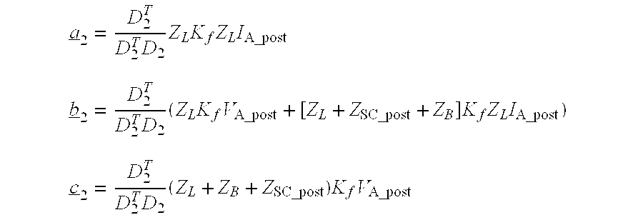
The coefficients a2, b2 and c2 may be calculated as follows: a _ 2 = D 2 T D 2 T D 2 Z L K f Z L I A_post ( 20 ) b _ 2 = D 2 T D 2 T D 2 ( Z L K f V A_post + [ Z L + Z SC_post + Z B ] K f Z L I A_post ) ( 21 ) c _ 2 = D 2 T D 2 T D 2 ( Z L + Z B + Z SC_post ) K f V A_post ( 22 )
Figure US06529010-20030304-M00005
The solution to the second distance-to-fault equation (16) gives a sought distance to the site of the fault as x 21 = Im ( b _ 2 ) - Im ( b _ 2 ) Im ( b _ 2 ) - 4 Im ( a _ 2 ) Im ( c _ 2 ) 2 Im ( a _ 2 ) ( 23 )
Figure US06529010-20030304-M00006
It has been found out that the second root of the distance-to-fault equation (18) gives unreasonable values of the distance to the fault and that the equation (23) therefore represents a sought solution to the first distance-to-fault equation (18).
By inserting the obtained value x21 into the second distance-to-fault equation (18), the corresponding fault resistance Rf2 is obtained by the relationship
R f2 =Re( a 2)x 21 2 −Re( b 2)x 21 +Re( c 2)  (24)
Determination of distance to fault and fault resistance is made by an iterative process which will be described below.
Before the iterative process for calculating the distance to fault can be started, a number of conditions must be fulfilled:
Independently of whether the fault is a category 1 fault or a category 2 fault, information about the value of fixed parameters, included in the equation systems, must be available. This relates to values of the backward and forward power networks, the length of the power transmission line, the impedance, the distance from station A to the series capacitors, and so on.
An assumption must be made on an initial value of distance to fault and fault resistance. This assumption may be made with arbitrary values within permissible limits.
When a fault has occurred, the type of fault and hence also the Kf matrix may be determined.
To be able to determine which of the calculating algorithms is to be used, knowledge must be gained as to on which side of SC&OVP the fault has occurred, that is, whether it is a fault 1 or a fault 2.
There must be a continuous access, both before and after a fault has occurred, of filtered values of current and voltage measured in one of the stations (A).
After the above conditions have been fulfilled, the distance-to-fault calculation is initiated.
In case of a fault 1, the following occurs:
Based on the current IA measured in station A after the occurrence of the fault, RSC and XSC are determined, for example with FIG. 7, whereupon ZSC in equation (2) may be determined.
the D1 auxiliary vectors are calculated according to equation (10)
the coefficients a1, b1 and c1 for the first distance-to-fault equation (9) are calculated according to equations (11), (12) and (13)
a first calculated value of the distance to the fault is calculated according to equation (14), and
a first value of the fault resistance is calculated according to equation (15).
The first calculated value of the distance to the fault is compared with the assumed value of the distance to the fault. If the difference between the values is greater than a pre-set maximally permissible difference value S1, the assumed value in equations (2) and (7) is replaced by the first calculated value of the distance to the fault and the fault resistance.
Thereafter, a new calculation procedure is carried out according to the above, which provides new values of the distance to the fault and the fault resistance. If the difference between the last calculated value of the distance to the fault and the first calculated value is greater than the maximally permissible difference value, the first calculated value in equations (2) and (7) is replaced by the last calculated values of the distance to fault and the fault resistance.
This iteration continues until the difference value of two consecutive calculation procedures is smaller than the set maximally permissible difference value, whereupon the last calculated values of the distance to fault and the fault resistance are regarded as the real values.
In case of a fault 2, the following occurs:
Based on the current IA measured in station A and an assumption of ZSC, after the occurrence of the fault, a preliminary value of the current through ZSC is calculated by means of equation (5). By means of the preliminary value of the current, a first value of RSC and XSC, that is also ZSC, may be obtained. The first calculated values are compared with the assumed value of ZSC. If the difference between the values is greater than a preset maximally permissible difference value S2, the set value in equation (6) is replaced by the first calculated value of ZSC. This iteration continues until the difference value of two consecutive calculation procedures is smaller than the set maximally permissible difference value, whereupon the last calculated value of ZSC constitutes the assumption of ZSC which is needed in equations (3) and (16).
the D2 auxiliary vectors are calculated according to equation (19)
the coefficients a2, b2 and c2 of the second distance-to-fault equation (18) are calculated according to equations (20), (21) and (22)
a first calculated value of the distance to the fault is calculated according to equation (23), and
a first value of the fault resistance is calculated according to equation (22).
The first calculated value of the distance to the fault is compared with the set value of the distance to the fault. If the difference between the values is greater than a pre-set maximally permissible difference value S3, the set value in equations (3) and (16) is replaced by the first calculated value of the distance to the fault and the fault resistance.
Thereafter, a new calculation procedure is carried out according to the above, which provides new values of the distance to the fault and the fault resistance. If the difference between the last calculated value of the distance to the fault and the first calculated value is greater than the maximally permissible difference value, the first calculated value in equations (3) and (16) is replaced by the last calculated values of the distance to fault and the fault resistance.
This iteration continues until the difference value of two consecutive calculation procedures is smaller than the set maximally permissible difference value, whereupon the last calculated values of the distance to fault and the fault resistance are regarded as the real values.
With access to the calculated values of the distances to fault, x11 and x21, and the corresponding fault resistances Rf1 and Rf2 and the equations described in the description, there is, according to the invention, a method for determining which of the distance-to-fault values represents the actual distance to the fault. The method is different depending on whether the fault is a three-phase fault or if it is an unsymmetrical fault, that is, if one or more phases is/are faultless.
If the fault is a three-phase fault, the following occurs:
Is Rf1>Rf2?Yes
If the answer is yes, it is assumed, as a first assumption, that the fault is a fault 2 and it is asked whether Rf2>R0? where R0 is a preset minimum value. If the answer is yes, the fault is a fault 2, that is, the calculated value of x21 is the true value of the distance to the fault. If the answer is no, it is a fault 1, that is, the calculated value of x11 is the true value of the distance to the fault.
Is Rf1>Rf2? No
If the answer is no, it is assumed, as a first assumption, that the fault is a fault 1 and it is asked whether Rf1>R0? where R0 is a preset minimum value. If the answer is yes, the fault is a fault 1, that is, the calculated value of x1 is the true value of the distance to the fault. If the answer is no, it is a fault 2, that is, the calculated value of x21 is the true value of the distance to the fault.
If the fault is an unsymmetrical fault, the currents through the fault resistances must first be determined for the two cases of fault.
For fault 1, the phase currents through the fault resistance may be determined with the aid of
i f(R,S,T)1 =i A(R,S,T) +i B(R,S,T)1  (25)
where
iA(R,S,T) are the phase currents measured in station A
iB(R,S,T)1 is determined with the aid of equation (2) (iB=Ia-post)
and for fault 2, the phase currents through the fault resistance may be determined with the aid of
i f(R,S,T)2 ==i A(R,S,T) +i B(R,S,T)2  (26)
 where
 iB(R,S,T)2 is determined with the aid of equation (3) (iB=I B-post)
The method for determining whether it is a question of a fault 1 or a fault 2 comprises, after a faultless phase has been identified in conventional manner, first determining the currents at the site of the fault in the faultless phase or phases for the two cases of fault according to equations (25), (2) and (26), (3), that is iff1 och iff2. Then follows the following procedure:
Is iff1>iff2?
Now, if iff1>iff2 it is considered, as a first assumption, that the fault is a fault 2 and if iff1<iff2 fit is considered, as a first assumption, that the fault is a fault 1.
The continued determination procedure is exactly identical with the procedure when the fault is a three-phase fault, that is: In case of a fault 2, it is asked whether Rf2>R0? where R0 is a preset minimum value. If the answer is yes, the fault is a fault 2, that is, the calculated value of x21 is the true value of the distance to the fault. If the answer is no, it is a fault 1, that is, the calculated value of x11 is the true value of the distance to the fault.
In case of a fault 1, it is asked whether Rf1>R0? where R0 is a preset minimum value. If the answer is yes, the fault is a fault 1, that is, the calculated value of x11 is the true value of the distance to the fault. If the answer is no, it is a fault 2, that is, the calculated value of x21 is the true value of the distance to the fault.
DESCRIPTION OF THE PREFERRED EMBODIMENTS
A device for determining the distance from a station, at one end of a transmission line, until the occurrence of a fault on the transmission line according to the described method comprises certain measuring devices, measurement value converters, members for iterative treatment of the calculating algorithms of the method, a possibility of inputting to the member known conditions regarding the parameters of the power networks and assumed values of distance to fault, fault resistance, etc., a VDU indicating the calculated distance to fault, and a printer for printout of the calculated distance to fault. FIG. 8 largely shows an embodiment of the device. Embodiments similar to those of FIG. 8 are within the scope of the invention.
FIG. 8 shows a transmission line 1 between two stations A and B. The line is provided with capacitors, protecting against overvoltages, forming the impedance ZSC. Station A accommodates measuring devices 2 and 3 for continuous measurement of all the phase currents and phase voltages. In the measurement converters 4 and 5, a number of these consecutively measured values, which in case of a fault are passed to a calculating unit 6, are filtered and stored. The calculating unit is provided with the calculating algorithms described, programmed for the iterative processes which are needed for calculating the distance to fault and the fault resistance.
Even before a fault occurred on the transmission line, the calculating unit was provided with a number of conditions and assumptions to be able to perform the calculation of the distance to fault etc. These conditions comprise values of the emf and the impedance of both a forward and a backward power network. The calculating unit is also supplied with known values of the length and impedance of the transmission line, the distance from station A to the series capacitors, set values of the distance to fault, the fault resistance, ZSC and the maximally permissible difference values S1, S2 and S3. In connection with the occurrence of a fault, information about the type of fault may be supplied to the calculating unit for determining the fault-type matrix Kf. In addition, after the occurrence of the fault, information is supplied as to whether the fault is positioned between the series capacitors and station B or whether the fault is positioned between station A and the series capacitors, that is, whether the fault is a fault 1 or a fault 2.
Then, when a fault has occurred, and the external conditions are fulfilled, the calculating procedure starts with the necessary iterations to obtain difference values which fall below the maximally permissible ones. The finally calculated values will then be transferred to a VDU which shows the distance to the fault and the magnitude of the fault resistance, respectively, for further actions. The device also comprises possibilities for printout of the result.
In the similar embodiments indicated above, parts of the embodiment according to FIG. 8 may be more or less integrated in the calculating unit.

Claims (12)

What is claimed is:
1. A method for location of a fault, and determination of a resultant fault resistance, occurring on a power transmission line which is series-compensated with capacitors, with a parallel-connected overvoltage protection device, between two stations (A) and (B), wherein distance to the fault from station (A) and the fault resistance are determined by means of values measured in station (A) of a voltage before (pre) and a voltage and a current after (post) the occurrence of the fault, wherein, if the fault occurred between the series capacitors and station B, the distance to the fault is determined by the steps of:
solving the expression: x 11 = Im ( b _ 1 ) - Im ( b _ 1 ) Im ( b _ 1 ) - 4 Im ( a _ 1 ) Im ( c _ 1 ) 2 Im ( a _ 1 )
Figure US06529010-20030304-M00007
which represents a first distance-to-fault equation;
solving the expression:
a 1 x 1 2 −b 1 x 1 +c 1 −R f1=0
for a, b and c, where a1, b1 and c1 designate complex coefficients and x1 represents the distance to the fault, and
employing a first auxiliary vector
D 1=(Z A +Z B +Z L)(I A post I A pre)+Z SC post I A post −Z SC pre I A pre
Or where
ZA is a source impedance of a backward power network;
ZB is a source impedance of a forward power network;
ZL is an impedance of a power transmission line;
Index, Post identifies a value after the occurrence of a fault;
Index, Pre identifies a value before the occurrence of the fault;
IA is a fault current;
ZS is a complex impedance; and
D1 T, which designates a transpose matrix of D1,
calculating a, b and c as follows: a _ 1 = D 1 T D 1 T D 1 Z L K f Z L I A_post b _ 1 = D 1 T D 1 T D 1 ( Z L K f [ V A_post + ( Z L - Z SC_post ) I A_post ] + Z B K f Z L I A_post ) ( 12 ) c _ 1 = D 1 T D 1 T D 1 ( Z L + Z B ) ( V A_post - Z SC_post I A_post ) K f ( 13 )
Figure US06529010-20030304-M00008
and where Im(a1), Im(b1) and Im(c1) are an imaginary part of the complex coefficients a, b1 and c, respectively, and
the fault resistance equals
R f1 =Re( a 1)x 11 2 −Re( b 1)x 11 +Re( c 1)
where Re(a1), Re(b1) and Re(c1) are a real part of the coefficients a 1, b 1 and c 1.
2. A method for location of a fault, and determination of the resultant fault resistance, which has occurred on a series-compensated power transmission line according to claim 1, wherein:
EA(R,S,R) is the emf of the backward power network
ZA(R,S,T) is the source impedances of the backward power network;
EB(R,S,T) is the emf of the forward power network;
ZB(R,S,T) is the source impedances of the forward power network;
ZL is the impedance of the power transmission line;
d is the distance in per unit from station A up to the series capacitor;
dZL is the impedance of the power transmission line between station A and the series-compensated capacitor; and
(1−d)dZL is the impedance of the power transmission line between the series capacitor and station B.
3. A method for location of a fault, and determination of the resultant fault resistance, which has occurred on a series-compensated power transmission line according to claim 1, wherein, when a fault has occurred, in order to characterize which type of fault has occurred, determining a fault-type matrix K f = [ k RR k SR k TR k RS k SS k TS k RT k ST k TT ]
Figure US06529010-20030304-M00009
according to the steps of:
determinism elements kRR . . . kTT in Kf depending on the type of fault according to a procedure wherein,
non-diagonal elements are given the value 0 if the phase in question is not concerned with the relevant fault and the value −1 if the phase is concerned with the relevant fault; and
The diagonal elements are given the value 1 if the phase in question has a fault to ground at the fault in question and adding the sum of the absolute values of the non-diagonal elements in the relevant row.
4. A method for location of a fault, and determination of the resultant fault resistance, which has occurred on a series-compensated power transmission line according to claim 1, wherein a parallel connection of the series capacitors and the overvoltage protection device comprises a non-linear impedance ZSC represented by a model equivalent impedance in the form of a series connection of a resistance RSC and a reactance XSC, individually determining the reactance and resistance as a function of a traversing current, determining an actual value of resistance and reactance, employing actual current which, after the occurrence of the fault, flows through the impedance, such that a non-lineat impedance is set as
Z SC =R SC +jX SC.
5. A method for location of a fault, and determination of a resultant fault resistance, which has occurred on a series-compensated power transmission line according to claim 4, wherein, if the fault occurred between the series capacitors and station B, measuring the actual current in station A for determining the non-linear impedance.
6. A method for location of a fault, and determination of a resultant fault resistance, which has occurred on a series-compensated power transmission line according to claim 5, wherein, if the fault occurred between station A and the series capacitors, an actual current IB is used for determining the non-linear impedance said current IB calculated in station B according to:
I B=((1−x 2)Z L +Z B +Z SC)−1.((Z A +x 2 Z L)I A−(E A −E B))
a value for assuming the non-linear impedance ZSC and the distance to fault x2, which current is used for determining a new value of ZSC which is compared with the assumed value of ZSC, and if the difference between the assumed value of ZSC and the new value is greater than a maximally permissible difference value S2, the assumed value in IB is replaced by the first calculated value of ZSC, repeating the previous calculation until the difference value of two consecutive calculating procedures is smaller than a maximum permissible difference value, whereupon a last obtained value of ZSC constitutes an assumed value which is employed for a final determination of the distance to fault and the fault resistance.
7. A method for location of a fault, and determination of the resultant fault resistance, which has occurred on a series-compensated power transmission line according to claim 1, wherein an assumption is made on a distance to fault “x” from station A and a fault resistance Rf.
8. A method for location of a fault, and determination of the resultant fault resistance, which has occurred on a series-compensated power transmission line according to claim 1, wherein, if the fault occurred between the series capacitors and station A, calculating an actual distance to fault and the fault resistance based on a calculating algorithm which comprises the equations
E A −E B =[Z A +Z B +Z L +Z SC pre ]I A pre  (1)
E A −E B =[Z A +x 1 Z L +Z SC post ]I A post−[(1−x 1)Z L +Z B ]I B post  (2)
V A post −V f=(x 1 Z L +Z SC post)I A post
I f =I A post +I B post
where quantities with an index “pre” relate to the value prevailing before a fault has occurred and
where quantities with an index “post” relate to the value prevailing immediately after the fault has occurred, and
where equation (1) is a vectorial equation of a power transmission line corresponding to the conditions immediately before the fault has occurred, and
where equation (2) is a vectorial equation of the power transmission line corresponding to the conditions immediately after the fault has occurred, and
where VA represents voltage measured in station A, and
where Vf relates to the voltage on the power transmission line where the fault has occurred and which is determined with the aid of
I f =K f V f/Rf
where If is the fault current through the fault resistance, and
where x1 is an unknown distance to fault from the power transmission line to the fault.
9. A method for location of a fault, and determination of the resultant fault resistance, which has occurred on a series-compensated power transmission line according to claim 8, wherein, if the fault occurred between station A and the series capacitors, the calculation of the actual distance to fault and the fault resistance is based on a calculating algorithm which comprises the equations
E A −E B [Z A +Z B +Z L +Z SC pre ]I A pre;  (1)
E A −E B [Z A +x 2 Z L ]I A post−[(1−x2)Z L +Z B +Z SC post ]I B post;  (3)
V A post −V f =x 2 Z L I A post;
and
I f =I A post +I B post;
where quantities with an index “pre” relate to the value prevailing before a fault has occurred and
where quantities with an index “post” relate to the value prevailing immediately after the fault has occurred, and
where equation (1) is a vectorial equation of a power transmission line corresponding to a conditions immediately before the fault has occurred, and
where equation (2) is a vectorial equation of the power transmission line corresponding to the conditions immediately after the fault has occurred, and
where VA represents a voltage measured in station A, and
where Vf relates to a voltage on the power transmission line where the fault has occurred and which is determined with the aid of
I f =K f V f /R f  (4)
where If relates to the fault current through the fault resistance, and
where x2 designates an unknown distance to fault from the end point A of the power transmission line to the site of the fault.
10. A device for carrying out the method for location of a fault, and determination of the resultant fault resistance, which has occurred on a series-compensated power transmission line between two stations A and B according to claim 1, wherein the device comprises measuring devices for continuous measurement of phase currents and phase voltages in one of the stations (A), measurement converters for filtering and storage of a number of these consecutively measured values, a calculating unit provided with the calculating algorithms of the method, including iteration possibilities, arranged for receiving signals in the form of measured, filtered and stored pre-fault phase currents and phase voltages as well as measured and filtered values of post-fault phase currents and phase voltages as well as signals indicating the emf (EA, EB) and impedance (ZA, ZB) of the backward and forward power network, the length (L) and impedance (ZL) of the power transmission line, and the distance (d) from station A to the series capacitors, assumed values of the distance to fault (x) and the fault resistance (Rf), data for deterring the type of fault (Kf) and, pre-determined maximally permissible difference values (S1, S2, S3).
11. A method for location of a fault, and determination of the resultant fault resistance, which has occurred on a power transmission line which is series-compensated with capacitors, with a parallel-connected overvoltage protection device, between two stations (A) and (B), wherein the distance to the fault from one station (A) and the fault resistance are determined by means of values measured in said station (A) of voltage before (pre) and voltage and current after (post) the occurrence of the fault, wherein, if the fault occurred between station A and the series capacitors, the distance to the fault is determined by the steps of:
solving the expression: x 21 = Im ( b _ 2 ) - Im ( b _ 2 ) Im ( b _ 2 ) - 4 Im ( a _ 2 ) Im ( c _ 2 ) 2 Im ( a _ 2 )
Figure US06529010-20030304-M00010
which represents a second distance-to-fault equation
a 2 x 2 2 −b 2 x 2 +c 2 −R f2=0
for a2, b2 and C2,
where a2, b2 and c2 designate complex coefficients and x2 represents the distance to the fault; and
employing a second auxiliary vector
D 2=(Z A +Z B +Z L)(I A post −I A pre)+Z SC post I A post −Z SC pre I A pre
Or where
ZA is a source impedance of a backward power network;
ZB is a source impedance of a forward power network;
ZL is an impedance of a power transmission line;
Index, Post identifies a value after the occurrence of a fault;
Index, Pre identifies a value before the occurrence of the fault;
IA is a fault current;
ZS is a complex impedance; and
D2 T, which designates the transpose matrix of D2,
calculating the coefficients a2, b2 and c2 as follows: a _ 2 = D 2 T D 2 T D 2 Z L K f Z L I A_post b _ 2 = D 2 T D 2 T D 2 ( Z L K f V A_post + [ Z L + Z SC_post + Z B ] K f Z L I A_post ) c _ 2 = D 2 T D 2 T D 2 ( Z L + Z B + Z SC_post ) K f V A_post
Figure US06529010-20030304-M00011
and where Im(a2), Im(b2) and Im(c2) are an imaginary part of the complex coefficients a 2, b 2 and c 2, and
the fault resistance equals
R f2 =Re( a 2)x 21 2 −Re( b 2)x 21 +Re( c 2)
where Re(a2), Re(b2) and Re(c2) are a real part of the complex coefficients a2, b2 and c2.
12. A method for determining which of a located fault according to claim 2 represents the true location, wherein, if the located fault is a three-phase fault, determining whether Rf1 is greater than Rf2, and if no, it is assumed, as a first assumption, that the fault is an Rf2 fault, and determining whether Rf2>R0
where R0 is a preset minimum value, and if so, the distance to fault is x21, and if not, the distance to fault is x11
and that if Rf1 is smaller than Rf2, it is assumed, as a first assumption, that the fault is an Rf1 fault, and determining whether Rf1>R0 and if so, the distance to fault is x1, and if not, the distance to fault is x2
if the located fault is an unsymmetrical fault, the phase currents through the fault resistance are first determined for a fault according to claim 1 according to
i f(R,S,T)1 =i A(R,S,T) +i B(R,S,T)1  (25)
where
iA(R,S,T) are the phase currents measured in station A
iB(R,S,T)1 is determined by means of equation (2) (iB=IB-post)
and for a fault according to
i f(R,S,T)2 ==i A(R,S,T) +i B(R,S,T)2
where
iB(R,S,T)2 is determined by means of equation (3) (iB=IB-post)
whereupon determining
whether if1 is greater than if2, and if so, it is assumed, as a first assumption, that the fault is an Rf2 fault, and determining whether Rf2>R0 where R0 is a preset minimum value, and if so, the distance to fault is x21, and if not, the distance to fault is x11
and if if1 is smaller than if2, it is assumed, as a first assumption, that the fault is an Rf1 fault, and determining whether Rf1>R0, and if so, the distance to fault is x1, and if not, the distance to fault is x2.
US09/582,087 1997-12-22 1998-12-18 Location of fault on series-compensated power transmission lines Expired - Lifetime US6529010B1 (en)

Applications Claiming Priority (3)

Application Number Priority Date Filing Date Title
SE9704797A SE513492C2 (en) 1997-12-22 1997-12-22 Method and apparatus for locating faults on a capacitor compensated power line with capacitor
SE9704797 1997-12-22
PCT/SE1998/002404 WO1999032894A1 (en) 1997-12-22 1998-12-18 Location of fault on series-compensated power transmission lines

Publications (1)

Publication Number Publication Date
US6529010B1 true US6529010B1 (en) 2003-03-04

Family

ID=20409503

Family Applications (1)

Application Number Title Priority Date Filing Date
US09/582,087 Expired - Lifetime US6529010B1 (en) 1997-12-22 1998-12-18 Location of fault on series-compensated power transmission lines

Country Status (9)

Country Link
US (1) US6529010B1 (en)
EP (1) EP1051632B1 (en)
AT (1) ATE296449T1 (en)
AU (1) AU1992799A (en)
CA (1) CA2316187C (en)
DE (1) DE69830339T2 (en)
ES (1) ES2243017T3 (en)
SE (1) SE513492C2 (en)
WO (1) WO1999032894A1 (en)

Cited By (13)

* Cited by examiner, † Cited by third party
Publication number Priority date Publication date Assignee Title
US20020019315A1 (en) * 1998-12-24 2002-02-14 Marco Nassi Electrical power transmission system using superconductors
US6721670B2 (en) 2001-09-13 2004-04-13 Abb Power Automation Ltd. Crossover fault classification for power lines with parallel circuits
US6738719B2 (en) 2001-09-13 2004-05-18 Abb Power Automation Ltd. Crossover fault classification for power lines with parallel circuits
US6741943B2 (en) * 2001-09-13 2004-05-25 Abb Power Automation Ltd. Crossover fault classification for power lines with parallel circuits
US6760670B2 (en) * 2001-09-13 2004-07-06 Abb Power Automation Ltd. Crossover fault classification for power lines with parallel circuits
US20100277181A1 (en) * 2006-01-12 2010-11-04 Abb Technology Ltd. Method and device for fault location in a two-terminal transmission or distribution power line
US20110178741A1 (en) * 2008-07-18 2011-07-21 Murari Saha Method and device for fault location of series-compensated transmission line
US20110264388A1 (en) * 2010-04-21 2011-10-27 Yanfeng Gong Fault location in electric power delivery systems
CN103245886A (en) * 2013-05-10 2013-08-14 国家电网公司 Method for fault localization by mounting series compensation capacitor device in circuit
WO2017128613A1 (en) * 2016-01-28 2017-08-03 中国电力科学研究院 Concomitant impedance protection method for half-wavelength transmission line
US20170227595A1 (en) * 2016-02-08 2017-08-10 General Electric Company Systems and Methods for Determining a Fault Location in a Three-Phase Series-Compensated Power Transmission Line
US20170227611A1 (en) * 2016-02-08 2017-08-10 General Electric Company Systems and Methods for Determining a Fault Location in a Three-Phase Series-Compensated Power Transmission Line
CN108776270A (en) * 2018-04-18 2018-11-09 云南电网有限责任公司怒江供电局 A kind of series compensation platform fault locator

Families Citing this family (2)

* Cited by examiner, † Cited by third party
Publication number Priority date Publication date Assignee Title
KR100350722B1 (en) * 2000-08-30 2002-08-28 주식회사 젤파워 Apparatus and method for locating fault distance in a power double circuit transmision line
US6476613B2 (en) 2000-12-20 2002-11-05 Abb Ab Method of fault location in parallel transmission lines with series compensation

Citations (4)

* Cited by examiner, † Cited by third party
Publication number Priority date Publication date Assignee Title
US4325098A (en) 1978-02-23 1982-04-13 Enertec Detection of the position of a fault on an electric link
US4559491A (en) 1982-09-14 1985-12-17 Asea Aktiebolag Method and device for locating a fault point on a three-phase power transmission line
EP0665441A2 (en) 1994-01-26 1995-08-02 Gec Alsthom Limited A method of locating the position of a fault on a power transmission line
US5455776A (en) 1993-09-08 1995-10-03 Abb Power T & D Company Inc. Automatic fault location system

Patent Citations (4)

* Cited by examiner, † Cited by third party
Publication number Priority date Publication date Assignee Title
US4325098A (en) 1978-02-23 1982-04-13 Enertec Detection of the position of a fault on an electric link
US4559491A (en) 1982-09-14 1985-12-17 Asea Aktiebolag Method and device for locating a fault point on a three-phase power transmission line
US5455776A (en) 1993-09-08 1995-10-03 Abb Power T & D Company Inc. Automatic fault location system
EP0665441A2 (en) 1994-01-26 1995-08-02 Gec Alsthom Limited A method of locating the position of a fault on a power transmission line

Cited By (22)

* Cited by examiner, † Cited by third party
Publication number Priority date Publication date Assignee Title
US6743984B2 (en) * 1998-12-24 2004-06-01 Pirelli Cavi E Sistemi S.P.A. Electrical power transmission system using superconductors
US20020019315A1 (en) * 1998-12-24 2002-02-14 Marco Nassi Electrical power transmission system using superconductors
US6721670B2 (en) 2001-09-13 2004-04-13 Abb Power Automation Ltd. Crossover fault classification for power lines with parallel circuits
US6738719B2 (en) 2001-09-13 2004-05-18 Abb Power Automation Ltd. Crossover fault classification for power lines with parallel circuits
US6741943B2 (en) * 2001-09-13 2004-05-25 Abb Power Automation Ltd. Crossover fault classification for power lines with parallel circuits
US6760670B2 (en) * 2001-09-13 2004-07-06 Abb Power Automation Ltd. Crossover fault classification for power lines with parallel circuits
US20100277181A1 (en) * 2006-01-12 2010-11-04 Abb Technology Ltd. Method and device for fault location in a two-terminal transmission or distribution power line
US8183871B2 (en) * 2006-01-12 2012-05-22 Abb Technology Ltd. Method and device for fault location in a two-terminal transmission or distribution power line
US9182441B2 (en) 2008-07-18 2015-11-10 Abb Technology Ag Method and device for fault location of series-compensated transmission line
US20110178741A1 (en) * 2008-07-18 2011-07-21 Murari Saha Method and device for fault location of series-compensated transmission line
US20110264388A1 (en) * 2010-04-21 2011-10-27 Yanfeng Gong Fault location in electric power delivery systems
US8525522B2 (en) * 2010-04-21 2013-09-03 Schweitzer Engineering Laboratories Inc Fault location in electric power delivery systems
CN103245886A (en) * 2013-05-10 2013-08-14 国家电网公司 Method for fault localization by mounting series compensation capacitor device in circuit
CN103245886B (en) * 2013-05-10 2015-12-23 国家电网公司 The Fault Locating Method of series compensation capacitance device is installed in the middle of a kind of circuit
WO2017128613A1 (en) * 2016-01-28 2017-08-03 中国电力科学研究院 Concomitant impedance protection method for half-wavelength transmission line
US10605852B2 (en) 2016-01-28 2020-03-31 China Electric Power Research Institute Company Limited Concomitant impedance protection method for half-wavelength transmission line
US20170227595A1 (en) * 2016-02-08 2017-08-10 General Electric Company Systems and Methods for Determining a Fault Location in a Three-Phase Series-Compensated Power Transmission Line
US20170227611A1 (en) * 2016-02-08 2017-08-10 General Electric Company Systems and Methods for Determining a Fault Location in a Three-Phase Series-Compensated Power Transmission Line
CN108603911A (en) * 2016-02-08 2018-09-28 通用电气公司 System and method for determining the abort situation in three-phase series compensation power transmission line
US10162015B2 (en) * 2016-02-08 2018-12-25 General Electric Company Systems and methods for determining a fault location in a three-phase series-compensated power transmission line
CN108603911B (en) * 2016-02-08 2020-09-29 通用电气公司 System and method for determining the location of a fault in a three-phase series-compensated power transmission line
CN108776270A (en) * 2018-04-18 2018-11-09 云南电网有限责任公司怒江供电局 A kind of series compensation platform fault locator

Also Published As

Publication number Publication date
DE69830339T2 (en) 2005-11-10
DE69830339D1 (en) 2005-06-30
CA2316187A1 (en) 1999-07-01
AU1992799A (en) 1999-07-12
SE513492C2 (en) 2000-09-18
EP1051632B1 (en) 2005-05-25
ATE296449T1 (en) 2005-06-15
ES2243017T3 (en) 2005-11-16
CA2316187C (en) 2009-03-24
WO1999032894A1 (en) 1999-07-01
SE9704797L (en) 1999-06-23
SE9704797D0 (en) 1997-12-22
EP1051632A1 (en) 2000-11-15

Similar Documents

Publication Publication Date Title
US6529010B1 (en) Location of fault on series-compensated power transmission lines
EP1172660B1 (en) Method and device for fault location in distribution networks
US6476613B2 (en) Method of fault location in parallel transmission lines with series compensation
US5446387A (en) Method and a device for determining a fault on a transmission line
EP2113778B1 (en) System and method for determining location of phase-to-phase fault or three-phase fault
US4996624A (en) Fault location method for radial transmission and distribution systems
US6397156B1 (en) Impedance measurement system for power system transmission lines
US20040167729A1 (en) Method and device of fault location
EP2051085A1 (en) Method for fault location on series compensated power transmission lines with two-end unsychronized measurement
EP2000811A9 (en) Method for determining location of phase-to-earth fault
US6420876B1 (en) Fault location in a medium-voltage network
WO2000050908A9 (en) Multi-ended fault location system
CN102484365A (en) A method of fault phase selection and fault type determination
EP1342095B1 (en) Fault location method and device
EP0464662B1 (en) Method and means for fault location in a multi-terminal network
US5493228A (en) Method and device for measuring and recreating the load current in a power network in connection with the occurrence of faults
US6173216B1 (en) Protective relay with improved, sub-window cosine filter
Sachdev et al. Determining locations of faults in distribution systems
Saha et al. Fault location in uncompensated and series-compensated parallel lines
US20020012540A1 (en) Method of fault location in parallel lines with series compensation
EP0795944A2 (en) Method for determining the operating parameters of at least one distance relay
DE10297214T5 (en) Crossover error classification for power lines with parallel connections
Bollen Additions to the method of critical distances for stochastic assessment of voltage sags
JPH11142465A (en) Ground-fault point detecting method
Izykowski et al. Location of faults in partially parallel transmission networks

Legal Events

Date Code Title Description
AS Assignment

Owner name: ABB AB, SWEDEN

Free format text: ASSIGNMENT OF ASSIGNORS INTEREST;ASSIGNORS:SAHA, MURARI;IZYKOWSKI, JAN;ROSOLOWSKI, EUGENIUSZ;AND OTHERS;REEL/FRAME:011067/0636;SIGNING DATES FROM 20000704 TO 20000816

STCF Information on status: patent grant

Free format text: PATENTED CASE

FPAY Fee payment

Year of fee payment: 4

FPAY Fee payment

Year of fee payment: 8

FEPP Fee payment procedure

Free format text: PAYOR NUMBER ASSIGNED (ORIGINAL EVENT CODE: ASPN); ENTITY STATUS OF PATENT OWNER: LARGE ENTITY

FPAY Fee payment

Year of fee payment: 12

AS Assignment

Owner name: ABB POWER GRIDS SWITZERLAND AG, SWITZERLAND

Free format text: ASSIGNMENT OF ASSIGNORS INTEREST;ASSIGNOR:ABB SCHWEIZ AG;REEL/FRAME:052916/0001

Effective date: 20191025