US652190A - Corn-planter. - Google Patents
Corn-planter. Download PDFInfo
- Publication number
- US652190A US652190A US72748499A US1899727484A US652190A US 652190 A US652190 A US 652190A US 72748499 A US72748499 A US 72748499A US 1899727484 A US1899727484 A US 1899727484A US 652190 A US652190 A US 652190A
- Authority
- US
- United States
- Prior art keywords
- plates
- planter
- foot
- rocking arms
- corn
- Prior art date
- Legal status (The legal status is an assumption and is not a legal conclusion. Google has not performed a legal analysis and makes no representation as to the accuracy of the status listed.)
- Expired - Lifetime
Links
- 210000005069 ears Anatomy 0.000 description 5
- 240000008042 Zea mays Species 0.000 description 4
- 235000005824 Zea mays ssp. parviglumis Nutrition 0.000 description 4
- 235000002017 Zea mays subsp mays Nutrition 0.000 description 4
- 235000005822 corn Nutrition 0.000 description 4
- 238000010276 construction Methods 0.000 description 3
- 240000001931 Ludwigia octovalvis Species 0.000 description 1
Images

Classifications
-
- A—HUMAN NECESSITIES
- A01—AGRICULTURE; FORESTRY; ANIMAL HUSBANDRY; HUNTING; TRAPPING; FISHING
- A01C—PLANTING; SOWING; FERTILISING
- A01C7/00—Sowing
- A01C7/18—Machines for depositing quantities of seed at intervals
Definitions
- 'I'he object of my invention is to provide a simple inexpensive mechanism whereby the corn will be dropped evenly and at proper intervals regardless of the unevenness of the ground over which the planter is passing.
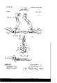
- Figure I is a side elevation of a corn-planter, showing my invention applied thereto.
- Fig. II is a plan view thereof with my improvements associated therewith.
- Fig. III is a detail side elevation, partly in section, of a pair of the rocking arms of my attachment, together with the pivoted footplates carried by said arms.
- Fig. IV is an enlarged vertical sectional view taken approximately on the line IV IV of Fig. III.
- 1 indicates the planterframe, 2 the furrow openers, 3 the seed-M boxes, et the operating-shaft that actuates the seed-dropping mechanism in the seedboxes, 5 the supporting wheels, and 6 the axle carrying said wheels, all these parts being of common construction.
- a hub 7 of an auxiliary wheel is rotatably arranged eccentrically in any suitable manner on the righthand side of the planter, which hub is in direct alinement with the furrow-opener on the right-hand side of said planter.
- a plurality of spokes S radiate from this hub 7. Upon the outside faces of the ends of these spokes are pivotally held the bent rocking arms 9.
- each footplate 12 indicates pivoted footplates, each of which comprises a pair of equal-sized oifset members 13, and at the center of each footplate is a pair of integral upwardly-projecting ears 14, the same coinciding with the plates l1, and passing through each pair of said coinciding plates are the pivot pins orbolts 15.
- Fixed to and extending from the center toward the rocking arms of each foot-plate is a bracket 16, to the upper end of which is pivoted the f center pivot-pin of a -rocking link 17.
- the pivot-pin of this link is in direct alinement with the pivot-pins 15.
- the inner endl of said rocking link is provided with a transverselyarranged slot 18, through which passes a pin 19, the ends thereof being seated in the plates 11.
- each rocking link 17 Pivotally held upon the outer end of each rocking link 17 is one end of a rod 20, the opposite end being secured tothe inside face of one of the ears 14, this last-mentioned pivot-pin being also in direct alinement with the pivot-pins 15.
- a box 2l in which the stub-axle 6, carrying the hub 7, rotates
- a verticallyarranged bar 22 held in any suitable manner to a box 2l (in which the stub-axle 6, carrying the hub 7, rotates) is a verticallyarranged bar 22, the same being braced in position by the horizontally-arranged bars 23, the forward ends of which are secured in any suitable manner to a vertical bar 23, which is held in a suitable manner at the end of the furrow-opener 2 on the right-hand side of the machine.
- a vertically-disposed pendent arm 2-1 To the lower end of the bar 22 is pivoted a vertically-disposed pendent arm 2-1, the lower end of which is provided with a curved inger25.
- a connecting-rod 26 To the upper end of this arm” 24 is pivoted the rear end of a connecting-rod 26, the forward end of which is connected to and adapted to actuate a pawl mechanism that is carried by the operating-shaft 4.
- Fixed to the connecting-rod 26 is one end of aretractile coil-spring 28, the rear end thereof being secured to the bar 22.
- Carried by an oppositely-arranged pair of rocking arms 9 and adjacent to the ends thereof are the outwardlyprojecting pins 29, the same being positioned so as to contact with the curved finger 25 of the pendent bar 24.
- An auxiliary wheel for cornplanters com prisingahub having spokes, rocking arms pivoted to the end of the spokes, means secured to the spokes with which the inner ends of the rocking arms engage to limit their movement, and the foot-plates pivoted to the outer ends of the rocking arms; substantially as described.
- Anauxiliary wheel for corn-planters eomprisinga hub having spokes, rocking arms pivoted to the ends of the spokes, means secured to the spokes with which the inner ends ot' the rocking arms engage to limit their movement, and the foot-plates having offset members and pivoted to the outer ends ofthe rocking arms; substantially as described.
- An auxiliary wheel for corn planters com prisingahub having spokes, clips secured to the spokes, rocking arms pivoted to the ends of the spokes, having their inner ends engaging with the clips whereby their movement is limited, the radial plates secured to the outer ends of the rocking arms, and the foot-plates having ears pivoted to the ends ot' the radial plates; substantially as described.
- An auxiliary wheel for corn-planters comprisinga hub having spokes, clips secured to the spokes, rocking arms pivoted to the ends of the spokes, having their inner ends engaging with the clips whereby their movement is limited, the radial plates secured to the outer ends of the rockingV arms, the footplates having ears pivoted to the ends of the radial plates, and brackets located between the ears, the rocking links having transverse slots at their inner ends, and pivoted to the brackets, the pins extending through the slots whereby the links are connected with the radial plates, and the rods connected with the outer ends of the links; substantially as described.
- G The combination, with a corn-planter; of an auxiliary wheel, the rim of which comprises a plurality of foot-plates, the hub of the auxiliary wheel being eccentrically arranged relative to the traction-wheels of the planter, and the auxiliary wheel being in alinement with one of the furrow-openers of the planter, and means actuated by said auxiliary wheel for operating the dropping mechanism of the planter; substantially as specilied.
- auxiliary wheel comprising a plurality ot' radially-arranged rocking arms, foot-plates pivotally arranged on the ends of the said rocking arms, the plates being adapted to contact with the grou nd,and means actuated by the said auxiliary Wheel for operating the dropping mechanism of the planter; substantially as specified.
- an auxiliary Wheel comprisin g a plurality of rocking arms,footplates pivoted upon the ends of said rocking arms, means whereby the swing of said foot-plates is restricted, means whereby the said dropping mechanism is actuated, and means carried by the auxiliary wheel for actuating the said last-mentioned means; substantially as specified.
- an auxiliary wheel comprising a plurality of rocking arms,footplates pivotally arranged at the ends of said rocking arms, which footplates each comprise a pair of offset portions,the offset portions of the adjacent plates'lying side by side, and means operated by said auxiliary wheel for actuating the corn-dropping mechanism ot' the planter; substantially as specified.
- an auxiliary wheel comprising a plurality of rocking arms, footplates pivotally arranged at the ends of said rocking arms, means whereby the swing of said foot-plates is restricted and equalized, means whereby the corn-dropping mechan# ism of the planter is actuated, and means carried by the auxiliary Wheel which engages with the first-mentioned means; substantially as specified.
- an auxiliary wheel comprising a plurality of pivoted rocking arms, means for limiting the movement of the rocking arms, and foot-plates pivotally arranged at the ends of said rocking arms; substantially as specified.
- an auxiliary wheel comprising a hub arranged to rotate at one side of the planter, a plurality of spokes integral with said hub, rocking arms pivotally secured to the outer ends of each of said spokes, foot-plates pivotally secured to the ends of said rocking arms, and means for limiting the movement of the rocking arms; sub-V stantially as specied.
- an auxiliary Wheel the rim of which comprises a plurality of footplates, each foot-plate being composed of oitset members, which offset members of the adjacent foot-plates lie side by side,.to form practically a continuous bearing when said auxiliary wheel rotates upon the ground; substantially as specified.
Landscapes
- Life Sciences & Earth Sciences (AREA)
- Soil Sciences (AREA)
- Environmental Sciences (AREA)
- Sowing (AREA)
Description
Patented 'Jung 9, :IQ-on.
No.` 652,l90.
J. E. LUCAS.
CORN PLANTEH.
(Application filed Aug. 17, 1899.) (No Model.) 2 Sheets-Sheet l,
M v 6 i ll u M o ,11H12 il Mmm 1E uw s M Y 1M f. .umuumuMinimum Z 15,
WIFL E E E E 5-. rfL; Mx *i .TE Luca/SG l l M l No. 652,190. Patented :une la, |900. J. LLUCAS.
CORN PLRNTER.,
(Application med Aug. 17, 1899.) (N0 Model.) 2 Sheets-Sheet 2.
UNITED `STATES PATENT OEE-ICE.-
AJAMES E. LUCAS, OF CLAYTON, ILLINOIS.
CORN-RL'ANTER.
SPECIFICATION forming part of Letters Patent No. 652,190, dated J' une 19, 1900.
Application iiled August 17,1899. Serial No. 727,484. (No model.)
To a/ZZ whom it may concern:
Beit known that I, JAMES E. LUCAs,a citizen of the United States, and a resident of Clayton, in the count-y of Adams and State of Illinois, have invented certain new and useful Improvements in Corn-Planters, of which the followingis a full,clear, and exact description, reference being had to the accompanying drawings, forming part of this specification.
'I'he object of my invention is to provide a simple inexpensive mechanism whereby the corn will be dropped evenly and at proper intervals regardless of the unevenness of the ground over which the planter is passing.
To the above purposes my invention consists in certain novel features of construction and arrangement of parts that will hereinafter be fully set forth and claimed.
Figure I is a side elevation of a corn-planter, showing my invention applied thereto. Fig. II is a plan view thereof with my improvements associated therewith. Fig. III is a detail side elevation, partly in section, of a pair of the rocking arms of my attachment, together with the pivoted footplates carried by said arms. Fig. IV is an enlarged vertical sectional view taken approximately on the line IV IV of Fig. III. Fig. Vis a plan view of one of a series of pivoted foot-plates that is made use of in carrying out my invention.
Referring by Arabic numerals to the` accompanying drawings, 1 indicates the planterframe, 2 the furrow openers, 3 the seed-M boxes, et the operating-shaft that actuates the seed-dropping mechanism in the seedboxes, 5 the supporting wheels, and 6 the axle carrying said wheels, all these parts being of common construction. A hub 7 of an auxiliary wheel is rotatably arranged eccentrically in any suitable manner on the righthand side of the planter, which hub is in direct alinement with the furrow-opener on the right-hand side of said planter. A plurality of spokes S radiate from this hub 7. Upon the outside faces of the ends of these spokes are pivotally held the bent rocking arms 9. The inner ends of these rocking arms pass through and play in retaining clips or straps 10, fixed upon the outside 4faces of the spokes 8 and limit the .movement `of the rocking arms. Bolted to the inside and outside-faces of the outer ends of these rocking arms 9 are pairs i of outwardlyprojecting shouldered radial plates 11.
12 indicates pivoted footplates, each of which comprises a pair of equal-sized oifset members 13, and at the center of each footplate is a pair of integral upwardly-projecting ears 14, the same coinciding with the plates l1, and passing through each pair of said coinciding plates are the pivot pins orbolts 15. Fixed to and extending from the center toward the rocking arms of each foot-plate is a bracket 16, to the upper end of which is pivoted the f center pivot-pin of a -rocking link 17. The pivot-pin of this link is in direct alinement with the pivot-pins 15. The inner endl of said rocking link is provided with a transverselyarranged slot 18, through which passes a pin 19, the ends thereof being seated in the plates 11. Pivotally held upon the outer end of each rocking link 17 is one end of a rod 20, the opposite end being secured tothe inside face of one of the ears 14, this last-mentioned pivot-pin being also in direct alinement with the pivot-pins 15. Held in any suitable manner to a box 2l (in which the stub-axle 6, carrying the hub 7, rotates) is a verticallyarranged bar 22, the same being braced in position by the horizontally-arranged bars 23, the forward ends of which are secured in any suitable manner to a vertical bar 23, which is held in a suitable manner at the end of the furrow-opener 2 on the right-hand side of the machine. To the lower end of the bar 22 is pivoted a vertically-disposed pendent arm 2-1, the lower end of which is provided with a curved inger25. To the upper end of this arm" 24 is pivoted the rear end of a connecting-rod 26, the forward end of which is connected to and adapted to actuate a pawl mechanism that is carried by the operating-shaft 4. Fixed to the connecting-rod 26 is one end of aretractile coil-spring 28, the rear end thereof being secured to the bar 22. Carried by an oppositely-arranged pair of rocking arms 9 and adjacent to the ends thereof are the outwardlyprojecting pins 29, the same being positioned so as to contact with the curved finger 25 of the pendent bar 24..
The operation is follows: As the planter moves forward the furrow-openers 2 4plow the usual furrows in the ground, in which IOO furrows travel the left-hand one of the supporting-wheels 5 and the foot-plates 12, respectively. As the auxiliary wheel, comprising the hub 7, spokes 8, rocking arms 9, and the foot-plates 12, rotates the pins 29 are successively brought into contact with the finger 25, and following this contact the pendent arm 24 swings upon its pivot, so that its upper end is swung forward. The connecting-rod 26 is also moved forward and in so doing the ratchet and pawl are actuated and the operating-shaft 4t is partly rotated. This actuation operates the seed-dropping mechanism, and `as soon as either of the pins 2.1) pass off from the finger the power stored in the coil-spring 28 will act to return the arm 24, connecting-rod 26, and pawl to their normal positions. As the planter moves forward the auxiliary wheel, comprising the hub 7, the spokes 8, the rocking arms 9, and the foot-plates 12, rotates and the said foot-plates l2 are successively brought into contact wit h.
the ground in the furrow made by the righthand furrow-opener, and as this action takes place the rocking arm 9 which carries the foot-plate 12 that is about to contact with the ground will swing slightly on its pivot,
and as a result thereof the foot-plate 12 carried ,by the said descending rocking arm will assume a horizon position, and while in this position will travel farther downward and into contact with the ground. Should the descending foot-plate come into contact with a higher portion of the ground than that on which the contact foot-plate rests, the inner end of the rocking arm 9, carrying the descendingfoot-plate, will swing to the rearend of its retaining-clip 10, and when the auxiliary wheel, comprising the hub 7, the spokes 8, the rocking arms 1, and the foot-plates 12, passes beyond a perpendicular line through the pivot-pin of -said rocking arm, which rocking arm now forms a lever, such auxiliary wheel will swing forward or over the center, which action brings the upper end of the rocking arm 9 to the forward end of said clip 10. This action colnpensates for the unevenness of the ground, and the auxiliary wheel will not excessively rotate while the planter is traveling a determinate distance forward. During the time the footplate 12 is in contact with theground the rocking linkV 17 changes its position slightly by swinging on its pivot, the slot in the upper end of the rocking link restricting its movement, and the movements of all of the links are made uniform and equalized by the connecting-rods 20. Owing to the number of rocking arms 9 and foot-plates 12 there will always be two ot' said plates in a horizontal position and in contact with 'the ground, and 'when in such position the offset members of the two foot-plates will lie .side by side, thus forming practically a continuous bearing on the ground. There is always a pair of the foot-plates 12 in contact with the ground at a time, and as said foot-plates occupy the ed in straight rows of equal distance apart V without the use ot a check-wire, and the attachment is simple, inexpensive, and can be readily applied to corn-planters of the present construction.
Having thus described my invention, the following is what I claim as new therein and desire to secure by Letters Patent:
l. An auxiliary wheel for cornplanters, com prisingahub having spokes, rocking arms pivoted to the end of the spokes, means secured to the spokes with which the inner ends of the rocking arms engage to limit their movement, and the foot-plates pivoted to the outer ends of the rocking arms; substantially as described.
2. Anauxiliary wheel for corn-planters, eomprisinga hub having spokes, rocking arms pivoted to the ends of the spokes, means secured to the spokes with which the inner ends ot' the rocking arms engage to limit their movement, and the foot-plates having offset members and pivoted to the outer ends ofthe rocking arms; substantially as described.
3. An auxiliary wheel for corn planters com prisingahub having spokes, clips secured to the spokes, rocking arms pivoted to the ends of the spokes, having their inner ends engaging with the clips whereby their movement is limited, the radial plates secured to the outer ends of the rocking arms, and the foot-plates having ears pivoted to the ends ot' the radial plates; substantially as described.
4. An auxiliary wheel for corn-planters comprisinga hub having spokes, clips secured to the spokes, rocking arms pivoted to the ends of the spokes, having their inner ends engaging with the clips whereby their movement is limited, the radial plates secured to the outer ends of the rockingV arms, the footplates having ears pivoted to the ends of the radial plates, and brackets located between the ears, the rocking links having transverse slots at their inner ends, and pivoted to the brackets, the pins extending through the slots whereby the links are connected with the radial plates, and the rods connected with the outer ends of the links; substantially as described.
5. The combinati-on, with the stub-axle and operating-shaft of a corn-planter; of a box located on the stub-axle, a frame, a ratchetwheel secured to the operating-shaft, a pendent arm supported by the frame, a connecting-rod pivoted to the upper end of the pendent arm, having a pawl engaging the ratchetwheel, a spring for retracting the connecting- IIO rod, and an auxiliary wheel comprising a hub having spokes, clips secured to the spokes, and rocking arms pivoted to the ends of the spokes, having pins adapted to engage with the lower end of the pendent arm, and their inner ends engaging with the clips whereby their movement is limited; substantially as described.
G. The combination, with a corn-planter; of an auxiliary wheel, the rim of which comprises a plurality of foot-plates, the hub of the auxiliary wheel being eccentrically arranged relative to the traction-wheels of the planter, and the auxiliary wheel being in alinement with one of the furrow-openers of the planter, and means actuated by said auxiliary wheel for operating the dropping mechanism of the planter; substantially as specilied.
7 In a corn-planter an auxiliary wheel comprising a plurality ot' radially-arranged rocking arms, foot-plates pivotally arranged on the ends of the said rocking arms, the plates being adapted to contact with the grou nd,and means actuated by the said auxiliary Wheel for operating the dropping mechanism of the planter; substantially as specified.
S. Inacornplanter,an auxiliary Wheel comprisin g a plurality of rocking arms,footplates pivoted upon the ends of said rocking arms, means whereby the swing of said foot-plates is restricted, means whereby the said dropping mechanism is actuated, and means carried by the auxiliary wheel for actuating the said last-mentioned means; substantially as specified.
9. In acorn-planter,an auxiliary wheel comprising a plurality of rocking arms,footplates pivotally arranged at the ends of said rocking arms, which footplates each comprise a pair of offset portions,the offset portions of the adjacent plates'lying side by side, and means operated by said auxiliary wheel for actuating the corn-dropping mechanism ot' the planter; substantially as specified.
10. In a corn-planter, an auxiliary wheel comprising a plurality of rocking arms, footplates pivotally arranged at the ends of said rocking arms, means whereby the swing of said foot-plates is restricted and equalized, means whereby the corn-dropping mechan# ism of the planter is actuated, and means carried by the auxiliary Wheel which engages with the first-mentioned means; substantially as specified.
ll. In a corn-planter, an auxiliary wheel comprising a plurality of pivoted rocking arms, means for limiting the movement of the rocking arms, and foot-plates pivotally arranged at the ends of said rocking arms; substantially as specified.
12. In a corn-planter, an auxiliary wheel comprising a hub arranged to rotate at one side of the planter, a plurality of spokes integral with said hub, rocking arms pivotally secured to the outer ends of each of said spokes, foot-plates pivotally secured to the ends of said rocking arms, and means for limiting the movement of the rocking arms; sub-V stantially as specied.
13. In a corn-planter, an auxiliary Wheel, the rim of which comprises a plurality of footplates, each foot-plate being composed of oitset members, which offset members of the adjacent foot-plates lie side by side,.to form practically a continuous bearing when said auxiliary wheel rotates upon the ground; substantially as specified.
14. The combination with a corn-planter of an auxiliary wheel having a hub, a plurality of radially-arranged rocking pivoted arms oscillating on the hub and carrying pivoted foot-plates, and means whereby the movement of said rocking arms is restricted; substantially as specified.
JAMES E'. LUCAS.
In presence of- JOI-IN R. WALLACE, J. R. MOFFETT.
Priority Applications (1)
| Application Number | Priority Date | Filing Date | Title |
|---|---|---|---|
| US72748499A US652190A (en) | 1899-08-17 | 1899-08-17 | Corn-planter. |
Applications Claiming Priority (1)
| Application Number | Priority Date | Filing Date | Title |
|---|---|---|---|
| US72748499A US652190A (en) | 1899-08-17 | 1899-08-17 | Corn-planter. |
Publications (1)
| Publication Number | Publication Date |
|---|---|
| US652190A true US652190A (en) | 1900-06-19 |
Family
ID=2720759
Family Applications (1)
| Application Number | Title | Priority Date | Filing Date |
|---|---|---|---|
| US72748499A Expired - Lifetime US652190A (en) | 1899-08-17 | 1899-08-17 | Corn-planter. |
Country Status (1)
| Country | Link |
|---|---|
| US (1) | US652190A (en) |
-
1899
- 1899-08-17 US US72748499A patent/US652190A/en not_active Expired - Lifetime
Similar Documents
| Publication | Publication Date | Title |
|---|---|---|
| US652190A (en) | Corn-planter. | |
| US844550A (en) | Corn-planter. | |
| US553728A (en) | Corn-planter | |
| US148246A (en) | Improvement in corn-planters | |
| US237420A (en) | Teeeitoey | |
| US434268A (en) | Corn-planter | |
| US448649A (en) | Corn-planter | |
| US470500A (en) | Corn planter | |
| US444030A (en) | Corn-planter | |
| US169432A (en) | Improvement in corn-planters | |
| US370664A (en) | Corn-planter | |
| US516176A (en) | anderson | |
| US193527A (en) | Improvement in corn-planters | |
| US447205A (en) | runyan | |
| US344214A (en) | And rolla butterfield | |
| US514868A (en) | Corn and cotton planter | |
| US215684A (en) | Improvement in marking attachments for corn-planters | |
| US763867A (en) | Corn-planter. | |
| US511260A (en) | Corn-planter | |
| US412150A (en) | Corn-planter | |
| US635715A (en) | Check-row planter. | |
| US206336A (en) | Improvement in seed-droppers | |
| US1064028A (en) | Check-row corn-planter. | |
| US530259A (en) | Check-row corn-planter | |
| US615949A (en) | Corn-planter |