US652188A - Span-wire pole and system. - Google Patents
Span-wire pole and system. Download PDFInfo
- Publication number
- US652188A US652188A US72462499A US1899724624A US652188A US 652188 A US652188 A US 652188A US 72462499 A US72462499 A US 72462499A US 1899724624 A US1899724624 A US 1899724624A US 652188 A US652188 A US 652188A
- Authority
- US
- United States
- Prior art keywords
- pole
- poles
- line
- span
- wire pole
- Prior art date
- Legal status (The legal status is an assumption and is not a legal conclusion. Google has not performed a legal analysis and makes no representation as to the accuracy of the status listed.)
- Expired - Lifetime
Links
- MJIHNNLFOKEZEW-UHFFFAOYSA-N lansoprazole Chemical compound CC1=C(OCC(F)(F)F)C=CN=C1CS(=O)C1=NC2=CC=CC=C2N1 MJIHNNLFOKEZEW-UHFFFAOYSA-N 0.000 description 3
- 238000005452 bending Methods 0.000 description 1
- 239000012141 concentrate Substances 0.000 description 1
- 238000010276 construction Methods 0.000 description 1
Images

Classifications
-
- H—ELECTRICITY
- H02—GENERATION; CONVERSION OR DISTRIBUTION OF ELECTRIC POWER
- H02G—INSTALLATION OF ELECTRIC CABLES OR LINES, OR OF COMBINED OPTICAL AND ELECTRIC CABLES OR LINES
- H02G7/00—Overhead installations of electric lines or cables
- H02G7/12—Devices for maintaining distance between parallel conductors, e.g. spacer
Definitions
- FIG. 1 is a perspective view of one of the stay or anchor poles of my system.
- Fig. 2 is a side elevation of one of the intermediate poles.
- Figs. 3 and 4 are cross-sections on the lines III III and IV IV of Figs. 1 and 2, respectively.
- Fig. 5 is a detail view of the weakened insulator-support I employ; and
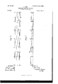
- Figs. 6 and '7 are diagrammatic plan and elevational views, respectively, showing my improved system.
- My invention relates to the overhead-wire systems of electric roads, and is designed to provide an improved pole and pole system therefor.
- FIG. 2 the ordinary intermediate pole I employ, which consists of an I-beam 2, which is straight up to about the point marked a, and is thence tapered upwardly by forming a tapered trough in its web, such as shown at 3 in Fig. 1.
- a casing 4 may be employed, which surrounds the pole from below the ground-level to a point above it, and it consists of a plate bent around the pole and having its overlapping ends riveted together.
- anchor-poles such as shown in Fig. 1, which are of greater strength and will prevent a break at any point from extending along the line.
- the ordinary poles employed are much weaker in resisting strain longitudinally of the line than in resistance to strain across the street, and to prevent bending or tipping of the poles longitudinally of the track I provide the anchor-pole, which consists of two I-beams 5, which are spread apart farther at the base than at the top and are connected by lattice-work 6.
- This pole is also tapered on the other two sides for at least a portion of its height by forming tapering troughs 3 in the webs of the I-beams, so that the pole tapers upwardly on all sides.
- a casing 7 may be employed for the portion of this pole at the ground-level, and this casing is preferably secured to prevent slipping along the poles by plates oneach side, which are riveted to the casing and to the webs of the I-beams.
- the plates 7 also act as tension-rods to stiiien the pole, being riveted to the webs at their upper and lower ends.
- These anchor-poles are Preferably placed with the lattice-work parallel to the tracks and used between every two or three of the ordinary poles, and on account of their resistance to longitudinal strain along the line they allow the use of light and cheap poles between them. I have found that it is more economical to thus concentrate a portion of the strength and resistance against strain in certain of the poles than to make them all of equal resisting power.
- Figs. 6 and 7, 9 9 are the trolley-wires, 1.0 the span-wires, and 11 the feed-wire.
- I preferably employ upon the smaller poles an insulator-pin 12, which is grooved or cut away, as shown, so as to weaken it against strain along the line. In case of a break on the line the pins on the intermediate poles will break, and thus bring the strain on the next anchor-pole, which is proportioned to carry it.
- a pole composed of two channeled sections connected together and having their webs provided with tapered troughs; substantially as described.
- Ataper pole composed of two channeled shapes, spaced wider apart at the bottom than at the top, and each having its web provided with a tapering trough or recess; substantially as described.
- An overhead line having poles arranged in a substantially-straight line, part of the intermediate poles being alternately weaker and stronger as to resistance against strains along the line; substantially as described.
- tor and having poles arranged in a substantially-straight line, part of the intermediate poles being arranged to resist a greater strain along the line than others of the poles; substantially as described.
- An overhead line having certain of its intermediate poles arranged to withstand less strain along the line than others in substantially the same line therewith, and provided with stronger insulator-pins than those of the Weaker poles; substantially as described.
- a pole having a base arranged to be inserted in a single hole, and composed of channeled shapes latticed together, the latticework extending substantially parallel with the wires carried by the pole; substantially I as described.
- An overhead line having a portion of the insulator-supports weakened, to withstand less strain along the line; substantially as de scribed.
- a pole composed of two channeled sections connected together, the web portions of the channels being tapered for a portion only of their length; substantially as described.
Landscapes
- Suspension Of Electric Lines Or Cables (AREA)
Description
Pafent'ed June l9, I900.
- .1. LANZ.
SPAN WIRE POLE AND SYSTEM.
{Apiwlicntion filed July 21, 1899.)
2 Sheets-Sheet I.
(No Model.)
WITNESSES THE Numus prrzns cu. wmo-uma, WAsnmcroN. n. c.
'No. e52,|as.
Patented June 19,1900. J, LANZ.
SPAN WIRE POLE AND SYSTEM.
(Application filed July 21, 1899.) (No Model.) 2 Sheets-$heet 2.
L N F N Q q) fi Q N M N N N S WITNESSES I INVEI'NITCIIRZP H M W l mam THE uomus Firms (20., PHOTO-LXYHQ. WASNWGTON. P. c.
UNITED STATES PATENT OFFICE.
JOHN LANZ, OF PITTSBURG, PENNSYLVANIA, ASSIGNOR TO THE CARNEGIE STEEL COMPANY, OF SAME PLACE.
SPAN-WIRE POLE AND SYSTEM.
SPECIFICATION forming part of Letters Patent No. 652,188, dated June 19, 1900.
Application filed July 21, 1899. Serial No. 724,624. (No model.)
To all whom, it may concern:
Be it known that I, JOHN LANZ, of Pittsburg, in the county of Allegheny and State of Pennsylvania, have invented a new and useful Improvement in Span-Wire Poles and Systems, of which the following is a full, clear, and exact description, reference being had to the accompanying drawings, forming part of this specification, in which- Figure 1 is a perspective view of one of the stay or anchor poles of my system. Fig. 2 is a side elevation of one of the intermediate poles. Figs. 3 and 4 are cross-sections on the lines III III and IV IV of Figs. 1 and 2, respectively. Fig. 5 is a detail view of the weakened insulator-support I employ; and Figs. 6 and '7 are diagrammatic plan and elevational views, respectively, showing my improved system.
My invention relates to the overhead-wire systems of electric roads, and is designed to provide an improved pole and pole system therefor.
In the drawings I show in Fig. 2 the ordinary intermediate pole I employ, which consists of an I-beam 2, which is straight up to about the point marked a, and is thence tapered upwardly by forming a tapered trough in its web, such as shown at 3 in Fig. 1. A casing 4 may be employed, which surrounds the pole from below the ground-level to a point above it, and it consists of a plate bent around the pole and having its overlapping ends riveted together.
With the above intermediate pole I prefer to employ, at any desired distances apart, anchor-poles, such as shown in Fig. 1, which are of greater strength and will prevent a break at any point from extending along the line. The ordinary poles employed are much weaker in resisting strain longitudinally of the line than in resistance to strain across the street, and to prevent bending or tipping of the poles longitudinally of the track I provide the anchor-pole, which consists of two I-beams 5, which are spread apart farther at the base than at the top and are connected by lattice-work 6. This pole is also tapered on the other two sides for at least a portion of its height by forming tapering troughs 3 in the webs of the I-beams, so that the pole tapers upwardly on all sides. A casing 7 may be employed for the portion of this pole at the ground-level, and this casing is preferably secured to prevent slipping along the poles by plates oneach side, which are riveted to the casing and to the webs of the I-beams. The plates 7 also act as tension-rods to stiiien the pole, being riveted to the webs at their upper and lower ends. "These anchor-poles are Preferably placed with the lattice-work parallel to the tracks and used between every two or three of the ordinary poles, and on account of their resistance to longitudinal strain along the line they allow the use of light and cheap poles between them. I have found that it is more economical to thus concentrate a portion of the strength and resistance against strain in certain of the poles than to make them all of equal resisting power.
In Figs. 6 and 7, 9 9 are the trolley-wires, 1.0 the span-wires, and 11 the feed-wire.
I preferably employ upon the smaller poles an insulator-pin 12, which is grooved or cut away, as shown, so as to weaken it against strain along the line. In case of a break on the line the pins on the intermediate poles will break, and thus bring the strain on the next anchor-pole, which is proportioned to carry it.
The advantages of my invention result from the economical and strong construction of pole which I employ for the anchor-poles and from the novel arrangement of poles in the system. I
Many changes may be made in the form and arrangement of the parts without departing from my invention.
I claim- 1. A pole composed of two channeled sections connected together and having their webs provided with tapered troughs; substantially as described.
2. Ataper pole, composed of two channeled shapes, spaced wider apart at the bottom than at the top, and each having its web provided with a tapering trough or recess; substantially as described.
3. An overhead line having poles arranged in a substantially-straight line, part of the intermediate poles being alternately weaker and stronger as to resistance against strains along the line; substantially as described.
4. A pole-line carrying an electric conduc.
tor and having poles arranged in a substantially-straight line, part of the intermediate poles being arranged to resist a greater strain along the line than others of the poles; substantially as described.
5. An overhead line, having certain of its intermediate poles arranged to withstand less strain along the line than others in substantially the same line therewith, and provided with stronger insulator-pins than those of the Weaker poles; substantially as described.
6. A pole having a base arranged to be inserted in a single hole, and composed of channeled shapes latticed together, the latticework extending substantially parallel with the wires carried by the pole; substantially I as described.
7. An overhead line, having a portion of the insulator-supports weakened, to withstand less strain along the line; substantially as de scribed.
8. A pole composed of two channeled sections connected together, the web portions of the channels being tapered for a portion only of their length; substantially as described.
In testimony whereof I have hereunto set my hand.
JOHN LANZ. Witnesses:
L. M. REDMAN, O. O. BITTNER.
Priority Applications (1)
| Application Number | Priority Date | Filing Date | Title |
|---|---|---|---|
| US72462499A US652188A (en) | 1899-07-21 | 1899-07-21 | Span-wire pole and system. |
Applications Claiming Priority (1)
| Application Number | Priority Date | Filing Date | Title |
|---|---|---|---|
| US72462499A US652188A (en) | 1899-07-21 | 1899-07-21 | Span-wire pole and system. |
Publications (1)
| Publication Number | Publication Date |
|---|---|
| US652188A true US652188A (en) | 1900-06-19 |
Family
ID=2720757
Family Applications (1)
| Application Number | Title | Priority Date | Filing Date |
|---|---|---|---|
| US72462499A Expired - Lifetime US652188A (en) | 1899-07-21 | 1899-07-21 | Span-wire pole and system. |
Country Status (1)
| Country | Link |
|---|---|
| US (1) | US652188A (en) |
-
1899
- 1899-07-21 US US72462499A patent/US652188A/en not_active Expired - Lifetime
Similar Documents
| Publication | Publication Date | Title |
|---|---|---|
| US652188A (en) | Span-wire pole and system. | |
| US634692A (en) | Pole or column. | |
| US1095202A (en) | Bridge construction. | |
| US788570A (en) | Trestle. | |
| US308826A (en) | Structural shape for columns | |
| CN207828712U (en) | A kind of straddle-type monorail composite bridge track | |
| US549643A (en) | Bridge | |
| US2136766A (en) | Third rail | |
| US514665A (en) | Edward w | |
| US257034A (en) | Lutheb e | |
| US741421A (en) | Composite girder or the like. | |
| US984802A (en) | Insulated metal cross-tie. | |
| US974225A (en) | Bridge for supporting trolley-wires by means of the catenary system. | |
| US1121313A (en) | Reinforced concrete construction. | |
| US919273A (en) | Reinforcing-truss for concrete structures. | |
| US611019A (en) | Alexander nurick | |
| US549851A (en) | Elevated railway | |
| US353691A (en) | Sylvanus d | |
| US1037969A (en) | Trolley-guard. | |
| US814339A (en) | Supporting structure for trolley-conductors. | |
| US176000A (en) | Improvement in elevated railways | |
| US541259A (en) | Rail-bond | |
| US935859A (en) | Suspended railway. | |
| US129479A (en) | Improvement in bridges | |
| US1546118A (en) | Floor-trough structure for bridges |