US652185A - Scooping, hoisting, and conveying apparatus. - Google Patents
Scooping, hoisting, and conveying apparatus. Download PDFInfo
- Publication number
- US652185A US652185A US74191599A US1899741915A US652185A US 652185 A US652185 A US 652185A US 74191599 A US74191599 A US 74191599A US 1899741915 A US1899741915 A US 1899741915A US 652185 A US652185 A US 652185A
- Authority
- US
- United States
- Prior art keywords
- head
- chamber
- scooping
- hoisting
- carrier
- Prior art date
- Legal status (The legal status is an assumption and is not a legal conclusion. Google has not performed a legal analysis and makes no representation as to the accuracy of the status listed.)
- Expired - Lifetime
Links
Images

Classifications
-
- E—FIXED CONSTRUCTIONS
- E02—HYDRAULIC ENGINEERING; FOUNDATIONS; SOIL SHIFTING
- E02F—DREDGING; SOIL-SHIFTING
- E02F3/00—Dredgers; Soil-shifting machines
- E02F3/04—Dredgers; Soil-shifting machines mechanically-driven
- E02F3/06—Dredgers; Soil-shifting machines mechanically-driven with digging screws
Definitions
- Figure 1 shows in side elevation the lower end of a scooping and hoisting apparatus constructed in accordance with my invention.
- Fig. 2 is a vertical longitudinal section of the same on the line II II of Fig. 1
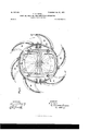
- Fig. 3 is a horizontal cross-section on the line III III of Fig. 1.
- My invention is designed for scooping,hoisting, or conveying materialsfor example, for unloading cargoes of ore from boats, &c.although it may be used for other purposes, such as shoveling or scooping ore or earth from the ground.
- 2 represents a case or cylinder which is adapted to contain a carrier composed of an endless chain or belt 3, carrying buckets 4.
- the case is adapted to be inserted into the hold of a vessel or other place from which materials are to be moved, and at its end is a chamber 2, in which is journaled a shaft 5,with sprocket-wheels 6,around which the chains 3pass.
- a shaft 5 At intervals around the circumference of the chamber 2' are openings 7 for the admission of the material, as explained below.
- scoops or buckets 12 To the exterior of the head 8 are fixed scoops or buckets 12, made in the form of projecting wings, which rotate in a plane transverse to the length of the carrier, and opposite to them the wall of the head 8 is provided with openings or windows 13, adapted to register with the openings 7 as I they pass over the latter during the rotation of .the head and to permit the passing of the material into the chamber 2.
- the front edges of the scoop are provided with sharp strong beaks 12, adapted to penetrate the ore or other material.
- a shaft or pin 14 At the lower end of the head 8 is a shaft or pin 14:, passing axially through the head and the wall of the chamber 2.
- This shaft or pin is fixed to the head 8, so as to rotate with the head, and at its outer end it is fitted with blades 15, made like the blades of a screw-propeller, besides being inclined upwardly, and at the other end in the cham her 2 it is provided with stirring-arms 16.
- the blades 15 dig into the ore or other material, holding the apparatus down to its work and steadying it and at the same time loosening the material and directing it into the path of the scoops 12.
- the head is rotary independently of the carrier, which does not rotate with it.
- the advantages of my invention will be appreciated by those skilled in the art.
- the device is compact and strong, and it affords means for the unloading of boats, due, enabling such work to be accomplished more rapidly than heretofore.
Description
Patented June 19, 1900.
F. H. KINDL. SCUOPING, HOISTING, AND CONVEYING APPARATUS.
(Application filed Dec. 29 1899.)
2 Sheets-Sheet I.
(No Model.)
INVENTOR WITNESSES- Patented lune l9, I900.
2 Sheets-Sheet 2.
INVENTOR m: "cams PETERS c0. mormLxmou WASNINGTON, a. c
F. H. KINDL.
SCOOPING, HUISTING, AND CONVEYING APPARATUS.
(Application filed Dec. 29, 1899.)
(No Model.)
WITNESSES UNITED S'rnT sf PATENT OFFICE.
FREDERICK H. KINDL, OF PITTSBURG, PENNSYLVANIA.
SQOOPING, HOISTING, AND CON VEYING APPARATUS.
SPECIFICATION forming part of Letters Patent No. 652,185, dated .Tune 19, 1900.
Application filed December 29, 1899. Serial No. 741,915. (No model.)
- ing drawings, forming part of this specification, in which Figure 1 shows in side elevation the lower end of a scooping and hoisting apparatus constructed in accordance with my invention. Fig. 2 is a vertical longitudinal section of the same on the line II II of Fig. 1, and Fig. 3 is a horizontal cross-section on the line III III of Fig. 1.
My invention is designed for scooping,hoisting, or conveying materialsfor example, for unloading cargoes of ore from boats, &c.although it may be used for other purposes, such as shoveling or scooping ore or earth from the ground.
In the drawings, 2 represents a case or cylinder which is adapted to contain a carrier composed of an endless chain or belt 3, carrying buckets 4. The case is adapted to be inserted into the hold of a vessel or other place from which materials are to be moved, and at its end is a chamber 2, in which is journaled a shaft 5,with sprocket-wheels 6,around which the chains 3pass. At intervals around the circumference of the chamber 2' are openings 7 for the admission of the material, as explained below.
8 is a rotary head which is set around the exterior of the chamber 2', so as to rotate thereon, and it is provided with driving-gear consisting of a circumferential gear-wheel 9 and pinions 10, the latter being driven by the shafts 11, which extend parallel with the case 2. 10 is a casing by which this gearing is protected. By using two shafts-one on each side of the case torsion and strain are prevented. To the exterior of the head 8 are fixed scoops or buckets 12, made in the form of projecting wings, which rotate in a plane transverse to the length of the carrier, and opposite to them the wall of the head 8 is provided with openings or windows 13, adapted to register with the openings 7 as I they pass over the latter during the rotation of .the head and to permit the passing of the material into the chamber 2. The front edges of the scoop are provided with sharp strong beaks 12, adapted to penetrate the ore or other material. At the lower end of the head 8 is a shaft or pin 14:, passing axially through the head and the wall of the chamber 2. This shaft or pin is fixed to the head 8, so as to rotate with the head, and at its outer end it is fitted with blades 15, made like the blades of a screw-propeller, besides being inclined upwardly, and at the other end in the cham her 2 it is provided with stirring-arms 16. When the head rotates, the blades 15 dig into the ore or other material, holding the apparatus down to its work and steadying it and at the same time loosening the material and directing it into the path of the scoops 12. The head is rotary independently of the carrier, which does not rotate with it.
In operation the case 2 is lowered into the hold of the vessel until the blades 15 come into contact with the body of the ore, and then the shafts 11 being driven by asuitable motor the head 8 is caused to rotate rapidly.
As above explained, this rotation causes the blades 15 to dig down into the ore and to draw the head downward upon and into the same, While the scoops 12, rotating with the head,
'dig laterally into the body of the ore and force it through the openings 13 and 7 into the chamber 2 as these openings come into register during the revolution of the head. Meanwhile the endless chains are caused to travel and the buckets gather up the material which enters the chamber 2' and raise it to the upper end of the case 2, where it is discharged. The loading of the buckets is facilitated by the stirring-arms 16, and I also provide the buckets at one edge with strong digging-blades 17, which penetrate the ore and facilitate the rapid and easy loading of the buckets.
The advantages of my invention will be appreciated by those skilled in the art. The device is compact and strong, and it affords means for the unloading of boats, due, enabling such work to be accomplished more rapidly than heretofore.
Within the scope of my invention many and adapted to deliver material thereto, substantially as described.
2. The combination of a chamber, a rotary head having scoops revolving in a plane transverse to the length of the carrier around the chamber and adapted to deliver material through openings in the chamber, and a carrier; substantially as described.
3. The combination of a rotary head carrylug scoops, screw-blades at the lower end of the head adapted to dig into the material and an elevating-carrier; substantially as described.
4. The combination of a chamber, a head carrying scoops revolving around the same,
independently of the carrier, in a plane transverse to the length of the carrier, and a series of buckets movable within the chamber; substantially as described.
5. The combination of a chamber, a rotary head, blades 15 on the outside of the head, an elevating-carrier, and stirring-blades within the chamber; substantially as described.
6. The combination of a case, a rotary head carrying scoops and driving-gear, a chamber into which the material is delivered by the scoops, and an endless carrier extending through the case and having an axle journaled in said chamber, said head being rotary independently of the carrier; substantially as described.
In testimony whereof I have hereunto set my hand.
FREDERICK I-I. KINDL.
Witnesses:
THOMAS W. BAKEWELL, G. I. HOLDSHIP.
Priority Applications (1)
| Application Number | Priority Date | Filing Date | Title |
|---|---|---|---|
| US74191599A US652185A (en) | 1899-12-29 | 1899-12-29 | Scooping, hoisting, and conveying apparatus. |
Applications Claiming Priority (1)
| Application Number | Priority Date | Filing Date | Title |
|---|---|---|---|
| US74191599A US652185A (en) | 1899-12-29 | 1899-12-29 | Scooping, hoisting, and conveying apparatus. |
Publications (1)
| Publication Number | Publication Date |
|---|---|
| US652185A true US652185A (en) | 1900-06-19 |
Family
ID=2720754
Family Applications (1)
| Application Number | Title | Priority Date | Filing Date |
|---|---|---|---|
| US74191599A Expired - Lifetime US652185A (en) | 1899-12-29 | 1899-12-29 | Scooping, hoisting, and conveying apparatus. |
Country Status (1)
| Country | Link |
|---|---|
| US (1) | US652185A (en) |
-
1899
- 1899-12-29 US US74191599A patent/US652185A/en not_active Expired - Lifetime
Similar Documents
| Publication | Publication Date | Title |
|---|---|---|
| US2401465A (en) | Grain loading and unloading device | |
| US2624129A (en) | Rotary grave-digging excavator | |
| US652185A (en) | Scooping, hoisting, and conveying apparatus. | |
| US1482524A (en) | Bin shoveler | |
| US2519077A (en) | Trench digging machine | |
| US902517A (en) | Shaft or tunnel boring mechanism. | |
| US1055548A (en) | Hydraulic excavator. | |
| US1529628A (en) | Excavating machine | |
| US1942839A (en) | Self-unloading boat | |
| US1760964A (en) | Load-ejecting apparatus for conveyers | |
| US1403530A (en) | Tunneling machine | |
| US1415869A (en) | Conveyer | |
| US2224282A (en) | Dredging, lifting, and conveying apparatus | |
| US265500A (en) | hereon | |
| US1403260A (en) | Dredge | |
| US994746A (en) | Ditcher and grader. | |
| US1370513A (en) | Apparatus for drying hay, grain, or the like | |
| US1383380A (en) | Slime-pump | |
| US1814093A (en) | Power driven hole digger | |
| US1708597A (en) | Excavator bucket | |
| US1414201A (en) | Excavator | |
| US1763769A (en) | Excavating tool for ditching or dredging machines | |
| US858180A (en) | Loading-barge for vessels. | |
| US1489600A (en) | Mining and loading machine | |
| DE869925C (en) | Bucket wheel excavators, especially for underground mining |