US652168A - Rotary engine. - Google Patents
Rotary engine. Download PDFInfo
- Publication number
- US652168A US652168A US70097599A US1899700975A US652168A US 652168 A US652168 A US 652168A US 70097599 A US70097599 A US 70097599A US 1899700975 A US1899700975 A US 1899700975A US 652168 A US652168 A US 652168A
- Authority
- US
- United States
- Prior art keywords
- steam
- valves
- valve
- shaft
- main shaft
- Prior art date
- Legal status (The legal status is an assumption and is not a legal conclusion. Google has not performed a legal analysis and makes no representation as to the accuracy of the status listed.)
- Expired - Lifetime
Links
- 210000003128 head Anatomy 0.000 description 11
- 230000009471 action Effects 0.000 description 3
- 230000008859 change Effects 0.000 description 3
- 238000010276 construction Methods 0.000 description 3
- 239000012530 fluid Substances 0.000 description 3
- 230000001105 regulatory effect Effects 0.000 description 3
- 239000013543 active substance Substances 0.000 description 2
- 239000003795 chemical substances by application Substances 0.000 description 2
- 210000005069 ears Anatomy 0.000 description 2
- 230000007246 mechanism Effects 0.000 description 2
- 238000006467 substitution reaction Methods 0.000 description 2
- 230000008901 benefit Effects 0.000 description 1
- 230000000694 effects Effects 0.000 description 1
- 210000000887 face Anatomy 0.000 description 1
- 230000005484 gravity Effects 0.000 description 1
- 230000009916 joint effect Effects 0.000 description 1
- 239000000463 material Substances 0.000 description 1
- 239000011435 rock Substances 0.000 description 1
- XLYOFNOQVPJJNP-UHFFFAOYSA-N water Substances O XLYOFNOQVPJJNP-UHFFFAOYSA-N 0.000 description 1
- 239000002023 wood Substances 0.000 description 1
Images


Classifications
-
- F—MECHANICAL ENGINEERING; LIGHTING; HEATING; WEAPONS; BLASTING
- F01—MACHINES OR ENGINES IN GENERAL; ENGINE PLANTS IN GENERAL; STEAM ENGINES
- F01C—ROTARY-PISTON OR OSCILLATING-PISTON MACHINES OR ENGINES
- F01C1/00—Rotary-piston machines or engines
- F01C1/08—Rotary-piston machines or engines of intermeshing engagement type, i.e. with engagement of co- operating members similar to that of toothed gearing
- F01C1/10—Rotary-piston machines or engines of intermeshing engagement type, i.e. with engagement of co- operating members similar to that of toothed gearing of internal-axis type with the outer member having more teeth or tooth-equivalents, e.g. rollers, than the inner member
- F01C1/103—Rotary-piston machines or engines of intermeshing engagement type, i.e. with engagement of co- operating members similar to that of toothed gearing of internal-axis type with the outer member having more teeth or tooth-equivalents, e.g. rollers, than the inner member the two members rotating simultaneously around their respective axes
Definitions
- D. M. BEARING. ROTARY ENGINE. Application filed m1. 3, 1899.
- This invention relates to steam-engines," and more especially to that class thereof known as rotary, and one object of the same is to produce an engine of this charac ter whose valves rotate in the steam-chest.
- FIG. 1 is a side elevation with one cylinder in section.
- FIG. 2 is a plan view with one cylinder in horizontal section.
- Fig. 3 is a cross-section on line 00 :n of Fig. 2.
- Fig. 4 is a section on linez a of Fig. 2.
- Fig. 5 is a section on line 3 3 ofFig. 2.
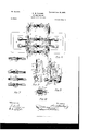
- Fig. 6 is a plan view of the steam inlet and exhaust pipes.
- Fig. 7 is a sectional View of the same.
- Fig. Sis a side elevation of the clutch mechanism.
- the numeral 5 designates the bed, on which is supported the (preferably circular) end pieces 26 of a plurality of casings 6, having hubs through which is journaled a main shaft 8.
- my improved engine as composed of two members arranged with a plurality of such casings end to end, and the main shaft continues through both of them and may carry a balance-wheel and other means by which powercan be communicated to suitable machinery to be driven;
- a greater number might be mounted on this shaft without departingfrom the spirit of my invention,
- the, casing 6 and on the shaft 8 is rigidly mounted the core 7, which, as shown in Fig. 3, is truly cylindrical, but set eccentric to said shaft, so as to leave a crescentshaped steam-space between its active face and the inner wall of the casing, and the cores of the two membersare set at points opposite each other.
- a steam-chest 12 having a removable cover 21, through which lead the inlet-pipes 14 and l f while the outlet-pipes 17 and 17 lead from the upper portion of the steam-space within the casing.
- Said inlet-pipes are connected with a common supply, as usual, and the outlets with a common exhaust.
- valves 52 and 52 on opposite sides of this common supply and the pipe let with similar valves 51 and 51, while the outlet 17 has valves 53 and 53, and 17 has valves 50 and 50.
- the valves without the supern'umerals have levers 3, provided with slots 8, engaged by pins r in a rod R, and the other valves have similar levers and slots engaged by pins '17; in a rod R, all as seen in Fig. 6, and when the rods R and R are moved by any suitable means the valves change from the positions seen in Fig. 7 to the opposite positions, as will be understood.
- passages 12 Within the steam-chest 12 are cored passages 12, leading from the inlets 14c and 14: to the inlet-ports 6 which enter the-casing near its top and on either side of the cylinderhead 9, as described below. These passages lead tangentially into transverse intersecting cylindrical openings which, contain rotary valves 15 and 15, each having about one-half of its periphery cut away, as shown in Fig.
- 18 18 designate pipes having outwardly closing check-valves 18 18, through which superheated air from the furnace is supplied to and admitted into the ports 6, as indicated in this view, and the use of the same is fully set forthbelow.
- Said valves 15 and 15 are mounted on shafts 31 and 31, carrying gears 22, intermeshing with a common idle-gear 23, which in turn meshes with a gear 25, fast on the main shaft 8, and the sizes of these gears are such that the valves and main shaft rotate simultaneously and in unison.
- the cylinder-head 9 is mounted for vertical reciprocation between antifriction devices consisting of balls or rollers 10, let into recesses in the side walls of a box 10, which is seated in a suitable cavity in the steam-chest 12, and said head moves in a plane in line with the center of the axis of the main shaft 3, as indicated by line E in Fig. 3.
- a pulley 23 mounted on the shaft 24 of the idle-gear 23 is a pulley 23, connected by a belt 45 or other means with a pulley 20*, whose shaft is geared, as at 20, to an upright shaft carrying a gravity or ball governor 20, and to the movable-collar of the latter is connected the fork 20 at one end of a rod 20 whose other end is attached to a crank-arm 40 on a shaft 40.
- the latter oscillates in bearings 40 on the bed and carries two crank-arms 40, each of which is connected by a rod 41 with a crankarm 34, fast on the shaft of one of two intermeshing toothed segments 35 36.
- M M designate emergency-passages cored within the steam-chest 12 and connecting the tangential passages 12 with the radial passages below the cylindrical openings for the rotary valves, and M are valves within these emergency-passages, all for a purpose to be described below.
- the steam-chests 12 may be connected by a suitable bracket 19, carrying bearings and supports for the various parts before described, and the yokes may have upright guides 29, moving through cars 30, supported by some fixed part.
- One of these cars may have a fixed block 63 and a movable block 64 hinged thereto, as at 65, in such manner as to form bearings for stubshafts 56 at opposite sides of the lever 56.
- 56 represents ears on said lever, through which moves a catch 61, having a lug 61 with an interposed spring 62 between the lug and one of the ears, so arranged as to throw the tip of the catch into engagement with holes or teeth on the top of the movable block 64.
- the lever 56 can be turned on its bearings 56 and set at any desired angle within the limits of its movements, as will be clear.
- the lower end of thelever is forked, as at 56, and the tips of its prongs engage at opposite sides of a ring 42, mounted in an annular groove in a collar 42, which is splined upon
- the other part A of this shaft has a collar 43, held by set-screw 43, adjustable thereon, and the meeting ends of the collars 42 and 43 have intermeshing teeth 43, while the meeting ends of the parts A B of the shaft are telescopic for at least a short distance.
- the lever 56 carries a thumb-lever 57, thrown out by a spring 60, and said thumb-lever has an elbow 57, connected by link 58 with a rod 59, sliding through eyes 56 and having its free end adapted to enter holes 42, formed radially in collar 42.
- the end plates 26 may support bearings 27 for the main shaft 8.
- the bracket 19 may carry bearings 19 for the shafts 31 31 and an additional bearing 19 for the shaft 24, and, as seen in section in Fig. 2, the ends of the sides of the box 10 may be beveled and set-screws 46 may bear longitudinally thereon, so as to adjust said sides inward toward the balls or rollers 10 for taking
- the shafts 31 31 pass through stufling-boxes 32, as shown, and similar boxes may be elsewhere provided 1 where necessary.
- rods R R are moved to the positions shown in Fig. 6, whereby the two inlet-pipes 14B are opened, as well as the two outlets 17, while the other inlets and outlets are closed, as in Fig. '7, and the active agent then flows in at the common supply and is directed to and through the left passage 12 of each member, as seen in Fig. 3, while the right outlet 17 of each is open and the right inlet and left outlet are closed.
- the gears 22, 23, and 25 shown in Fig. 4
- the balanced valves are caused to rotate in unison once for each revolution of the core, (see arrows in Fig.
- the rollers 10 obviously guide the head 9 in its movements to prevent binding or excessive friction, and when it grows loose the screws 16 are adjusted inward against the beveled ends of the side pieces of box 10 to approximate them slightly against the back of said rollers. It will be clear that since the inner edge of the cylinderhead comes to a point 9, or, rather, a sharp edge, since it extends entirely across the active face of the core, the engine can Work in either direction with equal facility, and the presence of the antifriction devices 1O on both sides 1 of the head 9 renders this operation successful.
- the pipes 18 are connected with the hot-air space in the furnace, and their valves 18 serve as check-valves, opening inwardly or toward the ports 6 and closing outwardly or in the opposite direction.
- the valve 15 cuts off the admission of live steam, and the steam already within the steam-space then acts on expansion, which is superi-nduced by the superheated air above mentioned.
- the core continues its revolution until a little beyond the position shown in Fig. 3 after the valve 15 cuts off the steam, and, obviously, the steam-space is now growing smaller.
- no vacuum is likely to be formed and the check-valve 18 has no .further work.
- any fluid that may stand in advance of the greatest radius of the core and on the other side of the cylinder-head 9 will not form a cushion, since it has free exit through open pipe 17, and, finally, when the core has revolved. to proper position the expanded steam is exhausted through this outlet 17 and the engine repeats its stroke.
- valves 51 and 53, Fig. 7, shall be open and valves 50' and 52 closed. Then the steam is admitted through inlet 14: and exhausted through outlet17. Obviously the rotation of the valve 15 or 15 which is idle, will have no effect, as also is the case with the adjustment taking place by means of the idle governor-valve 16 or 16 and the idle check-valve 18. I consider it important that the Working face or point 9 of the cylinder-head shall stand midway between the inlet-ports 6 and that this head shall have a movement on a line truly radial to the center of the main shaft, as indicated byline E. Otherwise the engine could. not be successfully reversed.
- valves M designates emergency passages controlled by valves M,which lattercan be opened to admit steam past the balanced valve when the engine stops with said valve closed, the object being merely to start the engine again after which the emergency-valve M is closed.
- valves M which lattercan be opened to admit steam past the balanced valve when the engine stops with said valve closed, the object being merely to start the engine again after which the emergency-valve M is closed.
- the balanced valve admit or cut off steam too early or too late or should its period of action be too long, it will be evident that by substituting another valve whose heel or port is of different length, as indicated byletter F, this matter can be controlled and regu lated as desired. Again, considerable adjustment may be effected by regulating the meshing of the teeth of the gears by which the balanced valve is driven from the main shaft.
- FIG. 8 Another means which I have provided for starting the engine if it should stop on expansion is shown in Figs. 8, 9, and 10.
- the lever 56 By releasing the catch 61 the lever 56 can be turned on its bearings 56", so that its fork 56 will slide the collar 42 on its spline on part B of the shaft 31 and disengage the intermeshing teeth 43. Parts A and B thus be- IIO ing disconnected, the part to which the balanced valve is attached can be revolved to bring its heel into communication between passage 12 and port 6 and the engine can be started.
- thumb-lever 57 and rod 59 the lower end of the latter can be entered into any of the holes 42 in the collar 42 whenever it is desired to lock this collar, and hence the balanced valve, in any particular position.
- this improved engine as comprising two parts or members mounted on a common shaft 8, and it will be understood that when so arranged one member is under steam while the other is completing its stroke or idle.
- This arrangement I consider highly important, if not absolutely necessary. Otherwise the engine must run on momentum for about or nearly half of every revolution. In fact, additional members might be added to the main shaft almost indefinitely, and they could be set quartering or otherwise to each other.
- the removability of the balanced valves is also important, as it permits the substitution of others having greater or shorter heels; or, if preferred, the lever 56 can be used to adjust the position of the heel of any valve with reference to the driven part A of the shaft 31 so that said valve shall act sooner or later.
- the rods R and R are connected and moved in unison; but if there are more than two members it will be quite possible to provide a clutch within the main shaft 8 and by use of the clutches or intermeshing teeth 43 to cause one part of the main shaft to rotate in a direction or at a speed differing from the other part.
- one rod, B would control the admission and exhaust of steam to and from one bank of members and the other rod, R, would control the other.
- the removable point 9? is also of advantage, in that it permits substitution when necessary. Should the engine never beintended for reversal, the active side or face of the cylinderhead 9 would by preference stand on line E, directly radial to the main shaft.
- the use of superheated air to assist expansion is also a valuable feature.
- the form of governor employed is not material.
- a rotary engine the combination with a casin g, a reciprocating cylinder-head at the top thereof, a branched steam-inlet entering .the casingthrough ports at opposite sides of said head, and an exhaust; of a core rotating within the casing and coacting with the inner extremity of said cylinder-head, pipes for superheated air entering said ports and having outwardly-closing check-valves in their bodies, rotary valves across said inlets and provided with suitable ports or heels, means for closing either inlet, and mechanism for simultaneously rotating said valves to open and close the ports at predetermined intervals, as and for the purpose set forth.
- a substantially-circular casing having an exhaust at its bottom, a reciprocating cylinderhead at its top, a branched inlet communicating with said casing through ports at opposite sides of said head, and a truly-circular core mounted within the casing eccentrically thereto; of pipes for superheated air leading into said ports and having outwardlyclosing check valves in their bodies, and means substantially as described for closing one inlet according to the direction of rotation desired and for opening and closing the other meanwhile at predetermined intervals, as and for the purpose set forth.
- a rotary engine the combination with a casing, a main shaft therethrough, a core set eccentrically within the casing upon said shaft, a reciprocating cylinder-head, a removable point at its inner extremity coacting with the active face of the core, a yoke adj ustably bolted to said head, eccentrics on said shaft exterior to the casing and truly parallel with the active face of the core, and connections between said eccentrics and yoke; of a steamchest on the casing provided with an inletpassage communicating with the inlet-port to the casing, an exhaust fromthe latter, a rotary valve set in a cylindrical opening intersecting said passage, said valve having a port orheel removed from its face, and connections between the shaft of the valve and the main shaft, as and for the purpose set forth.
- a rotary engine the combination with the casing containing a core set on the main shaft, a reciprocating cylinder-head, an inletport at one side of the head, and an exhaust; of a rotary valve set in a cylindrical opening intersecting said passage, gearing between this valve and they main shaft, a governorvalve also set in a cylindrical opening in said passage,fa governor belted to the main shaft,
- a rotary engine the combination with a casing containing a core set on the main shaft, a cylinder-head reciprocated by said shaft, and an exhaust; of asteam-chest having inlet-passages leading to ports opening into the casing on opposite sides of said head, simultaneously-moving valves in these passages, other valves for closing one passage and opening the other, governor-valves set in cylindrical openings intersecting said passages, toothed segments connecting the shafts of these valves on the exterior of the chest, one of them having a crank-arm, a governor driven from the main shaft, and a rod connecting said governor and crank-arm, all as andfor the purpose set forth.
- a rotary engine the combination with a plurality of casings, a main shaft extending through them, cores on the shaft Within the casings, a reciprocating cylinder head for each casing, and inlets and exhausts; of a steam-chest for each casin g with an inlet-passage leading to its port and a cylindrical open ing intersecting such passage, rotary valves in such openings, a valve-shaft driven from the main shaft, and clutch connections between the valve-shaft and the shafts of the individual valves, as and for the purpose set forth.
Landscapes
- Engineering & Computer Science (AREA)
- Mechanical Engineering (AREA)
- General Engineering & Computer Science (AREA)
- Engine Equipment That Uses Special Cycles (AREA)
Description
Patented lune I9. I900. D. M. BEARING. ROTARY ENGINE. (Application filed m1. 3, 1899.)
8 Sheafs-Sheet I.
(No Model.)
m: noRFHS PETERS co. mow-urns" WASHYNCYON, u c.
No. 652,!68. Patented lune l9, I900.
o. M. BEARING. ROTARY ENGINE.
, (Application filed Jan. 3, 1899.)
( N 0 M 0 d e l J) No. 652,168. Patented lune l9, I900. D. M. BEARING.
ROTARY ENGINE.
(Application filed Jan. 3, 1899.)
(No Model.) a Sheets-Sheet 4.
All Illllllllllllll ll i-n-i No. 652,|68. Patented lune l9, I900. D. M. BEARING.
' ROTARY ENGINE.
(Application filed Jan. 3, 1899.) (N0 Modem 6 Sheets-Sheet 5.
(No Model.)
Patented June l9, I900.
D. M. BEARING. ROTARY ENGINE.
(Applicationfiled Jan. 3, 1399.)
6 Sheets-Sheet 6.
UNITED STATE s PATENT OF ICE.
DAVID M. DEARING, OF DENVER, COLORADO, ASSIGNOR TO GUILFORD S.
WOOD, OF SAME PLACE, AND HENRY P.
MICHIGAN.
VDEARING, or SANDSTONE,
ROTARY ENG l N E.
SPECIFICATION forming part of Letters Patent No. 652,168, dated June, 19, 1900. Application filed January 3, 1899. Serial No. 700,975. (No model.)
To (l/ZZ whom, it may concern:
Be it known that I, DAVID M. DEARING, a citizen of the United States, residing at Den ver, in the county of Arapahoe and State of Colorado, have invented certain new and useful Improvements in Rotary Engines; and I do hereby declare the following to be a full, clear, and exact description of theinvention, such as will enable others skilled in the art to which it appertains to make and use the same.
This invention relates to steam-engines," and more especially to that class thereof known as rotary, and one object of the same is to produce an engine of this charac ter whose valves rotate in the steam-chest.
Further objects of the present invention will appear herein.
To this end the present invention consists, broadly, in a rotary engine having rotary balanced valves, which valves are changeable so as to change the speed of rotation and in cer-' tain other details of construction cooperating therewith, all as hereinafter more fully specitied and claimed, and as illustrated in the accompanying drawings, wherein Figure l is a side elevation with one cylinder in section. Fig. 2 is a plan view with one cylinder in horizontal section. Fig. 3 is a cross-section on line 00 :n of Fig. 2. Fig. 4 is a section on linez a of Fig. 2. Fig. 5 is a section on line 3 3 ofFig. 2. Fig. 6 is a plan view of the steam inlet and exhaust pipes. Fig. 7 is a sectional View of the same. Fig. Sis a side elevation of the clutch mechanism. Fig. 9 is a cross-sectional view of the same, and Fig. 10 is a longitudinal section thereof:
Referring to the said drawings, the numeral 5 designates the bed, on which is supported the (preferably circular) end pieces 26 of a plurality of casings 6, having hubs through which is journaled a main shaft 8. In -the present instance I have shown my improved engine as composed of two members arranged with a plurality of such casings end to end, and the main shaft continues through both of them and may carry a balance-wheel and other means by which powercan be communicated to suitable machinery to be driven; However, it will be understood that a greater number might be mounted on this shaft without departingfrom the spirit of my invention,
ployed on this shaft, if desired. I consider two members. as the best arrangement,
however, and as they are substantial duplicates of each other a description of one will suffice for both save where reference is made to their joint action.
WVithin the, casing 6 and on the shaft 8 is rigidly mounted the core 7, which, as shown in Fig. 3, is truly cylindrical, but set eccentric to said shaft, so as to leave a crescentshaped steam-space between its active face and the inner wall of the casing, and the cores of the two membersare set at points opposite each other. Mounted upon the casing 6 is a steam-chest 12, having a removable cover 21, through which lead the inlet-pipes 14 and l f while the outlet- pipes 17 and 17 lead from the upper portion of the steam-space within the casing. Said inlet-pipes are connected with a common supply, as usual, and the outlets with a common exhaust. In Fig. 6 itwill be seen that the inlet-pipe 14 is provided with valves 52 and 52 on opposite sides of this common supply and the pipe let with similar valves 51 and 51, while the outlet 17 has valves 53 and 53, and 17 has valves 50 and 50. The valves without the supern'umerals have levers 3, provided with slots 8, engaged by pins r in a rod R, and the other valves have similar levers and slots engaged by pins '17; in a rod R, all as seen in Fig. 6, and when the rods R and R are moved by any suitable means the valves change from the positions seen in Fig. 7 to the opposite positions, as will be understood. Hence it is possible by simply moving the rod R or R to admit steam to either of the inlet- pipes 14 or 14 and to correspondingly change the outlets thereof, as necessary.
Within the steam-chest 12 are cored passages 12, leading from the inlets 14c and 14: to the inlet-ports 6 which enter the-casing near its top and on either side of the cylinderhead 9, as described below. These passages lead tangentially into transverse intersecting cylindrical openings which, contain rotary valves 15 and 15, each having about one-half of its periphery cut away, as shown in Fig.
- balanced valves 15 15.
3, although it might be less than a half, as indicated by dotted lines F, and radially from these openings the passages are continued downward through governor valves, described below, into the inlet-ports 6. 18 18 designate pipes having outwardly closing check-valves 18 18, through which superheated air from the furnace is supplied to and admitted into the ports 6, as indicated in this view, and the use of the same is fully set forthbelow. Said valves 15 and 15 are mounted on shafts 31 and 31, carrying gears 22, intermeshing with a common idle-gear 23, which in turn meshes with a gear 25, fast on the main shaft 8, and the sizes of these gears are such that the valves and main shaft rotate simultaneously and in unison.
The cylinder-head 9 is mounted for vertical reciprocation between antifriction devices consisting of balls or rollers 10, let into recesses in the side walls of a box 10, which is seated in a suitable cavity in the steam-chest 12, and said head moves in a plane in line with the center of the axis of the main shaft 3, as indicated by line E in Fig. 3.
28 repesents collars surrounding eccentrics on the main shaft, from which collars rise upright rods 28, connected with a cross-bar 13 and forming a yoke. From said bar depend bolts 9 with nuts 9* above and below the crossbar to permit the finest adjustment, and said bolts lead through stuffing-boxes to the cylinder-head, so that the latter shall have the proper reciprocation. At its inner extremity said head carries a point9, removable longitudinally or in line with the axis and which coacts with the active face of the core 7 at all times, as regulated by the nuts 9 on the bolts 9 above and below the cross-bar.
Mounted on the shaft 24 of the idle-gear 23 is a pulley 23, connected by a belt 45 or other means with a pulley 20*, whose shaft is geared, as at 20, to an upright shaft carrying a gravity or ball governor 20, and to the movable-collar of the latter is connected the fork 20 at one end of a rod 20 whose other end is attached to a crank-arm 40 on a shaft 40. The latter oscillates in bearings 40 on the bed and carries two crank-arms 40, each of which is connected by a rod 41 with a crankarm 34, fast on the shaft of one of two intermeshing toothed segments 35 36. The latter are respectively fixed on the shafts 33 and 33 of governor- valves 16 and 16, working in transverse cylindrical openings intersecting the passages in the steam-chest 12. (See Figs. 3 and 5.) When the engine revolves at an excessive speed, the balls of the governor are thrown out, its collar rises, and the rod 20 draws upward on the arm 40. The latter rocks the shaft 40 in its bearings, and this through the arm 40, rod 41, and segments 35 36 causes the shafts 33 and 33 to turn and the valves 16 and 16 to more or less close the ports in the steam-chest irrespective of the Thus it will be seen that the governor is automatic in its action,
' part B of shaft 31.
- up any looseness of parts.
and yet accurately controls the admission of the active agent to the engine or its members.
The letters M M designate emergency-passages cored within the steam-chest 12 and connecting the tangential passages 12 with the radial passages below the cylindrical openings for the rotary valves, and M are valves within these emergency-passages, all for a purpose to be described below.
6 is a single exhaust-openin g from the bottom of the casingdirectly opposite the line of movement of the cylinder-head, and its function will be described hereinafter.
The steam-chests 12 may be connected by a suitable bracket 19, carrying bearings and supports for the various parts before described, and the yokes may have upright guides 29, moving through cars 30, supported by some fixed part. One of these cars (see Figs. 8 and 9) may have a fixed block 63 and a movable block 64 hinged thereto, as at 65, in such manner as to form bearings for stubshafts 56 at opposite sides of the lever 56. 56 represents ears on said lever, through which moves a catch 61, having a lug 61 with an interposed spring 62 between the lug and one of the ears, so arranged as to throw the tip of the catch into engagement with holes or teeth on the top of the movable block 64. By this means the lever 56 can be turned on its bearings 56 and set at any desired angle within the limits of its movements, as will be clear. The lower end of thelever is forked, as at 56, and the tips of its prongs engage at opposite sides of a ring 42, mounted in an annular groove in a collar 42, which is splined upon The other part A of this shaft has a collar 43, held by set-screw 43, adjustable thereon, and the meeting ends of the collars 42 and 43 have intermeshing teeth 43, while the meeting ends of the parts A B of the shaft are telescopic for at least a short distance. (See Fig. 10.) The lever 56 carries a thumb-lever 57, thrown out by a spring 60, and said thumb-lever has an elbow 57, connected by link 58 with a rod 59, sliding through eyes 56 and having its free end adapted to enter holes 42, formed radially in collar 42.
Details of construction herein elsewhere shown may be adopted or not, according to the fancy of the manufacturer. In fact, the exact construction and arrangement of parts is not essential. The end plates 26 may support bearings 27 for the main shaft 8. The bracket 19 may carry bearings 19 for the shafts 31 31 and an additional bearing 19 for the shaft 24, and, as seen in section in Fig. 2, the ends of the sides of the box 10 may be beveled and set-screws 46 may bear longitudinally thereon, so as to adjust said sides inward toward the balls or rollers 10 for taking The shafts 31 31 pass through stufling-boxes 32, as shown, and similar boxes may be elsewhere provided 1 where necessary.
rods R R are moved to the positions shown in Fig. 6, whereby the two inlet-pipes 14B are opened, as well as the two outlets 17, while the other inlets and outlets are closed, as in Fig. '7, and the active agent then flows in at the common supply and is directed to and through the left passage 12 of each member, as seen in Fig. 3, while the right outlet 17 of each is open and the right inlet and left outlet are closed. Through the gears 22, 23, and 25 (shown in Fig. 4) the balanced valves are caused to rotate in unison once for each revolution of the core, (see arrows in Fig. 3,) and through the pulleys and belting the governor is caused to control the movements of the governor-valves 16 16 to prevent an excess-' ive inlet of steam. The rotation of the core causes similar movement of the main shaft 8 and of the eccentrics thereon, which are set with their faces truly parallel and concentric with the active face of the core, and through the instru mentality of the yoke above described these eccentrics cause the vertical reciprocation of the cylinder-head 9, which can be adjusted by means of the bolts 9 and nuts 9 so that its point 9 is held always in position to coact with said active face, yet either with or without making frictional contact therewith. The rollers 10 obviously guide the head 9 in its movements to prevent binding or excessive friction, and when it grows loose the screws 16 are adjusted inward against the beveled ends of the side pieces of box 10 to approximate them slightly against the back of said rollers. It will be clear that since the inner edge of the cylinderhead comes to a point 9, or, rather, a sharp edge, since it extends entirely across the active face of the core, the engine can Work in either direction with equal facility, and the presence of the antifriction devices 1O on both sides 1 of the head 9 renders this operation successful. The pipes 18 are connected with the hot-air space in the furnace, and their valves 18 serve as check-valves, opening inwardly or toward the ports 6 and closing outwardly or in the opposite direction.
Vith the single exhaust 6" closed, the operation is now as follows: Steam enters at 14, passes down passage 12, and finds the valve 15 closed. The rotation of the core '7 in the direction of the arrow thereon finally brings its point of greatest radius under the cylinder-head 9, and the forward small end of the crescent-shaped steam-space begins to form just beneath the port 6, At this time in order that no vacuum shall form therein the checkvalve 18 at the left opens automatically under the suction set up, and a small charge of superheated air is admitted to said steamspace. Continued rotation of the core, and hence of the valves, then brings the opening or heel or port of the left valve into communication with passage 12 and port 6*, and steam is admitted under pressure. This automatically closes the check-valve 18, and the steam enters and fills the crescent-shaped steam-space.
At the proper moment, due to the timing of the parts, the valve 15 cuts off the admission of live steam, and the steam already within the steam-space then acts on expansion, which is superi-nduced by the superheated air above mentioned. The core continues its revolution until a little beyond the position shown in Fig. 3 after the valve 15 cuts off the steam, and, obviously, the steam-space is now growing smaller. Hence no vacuum is likely to be formed and the check-valve 18 has no .further work. Meanwhile any fluid that may stand in advance of the greatest radius of the core and on the other side of the cylinder-head 9 will not form a cushion, since it has free exit through open pipe 17, and, finally, when the core has revolved. to proper position the expanded steam is exhausted through this outlet 17 and the engine repeats its stroke.
WVith the single exhaust 6 open the action is substantially the same save that the exhaust of the expanded steam is at the bottom, and hence the engine does not necessarily carry the expanded steam around the inactive side of its revolution.
To reverse the engine, it is only necessary to move rods R B so that valves 51 and 53, Fig. 7, shall be open and valves 50' and 52 closed. Then the steam is admitted through inlet 14: and exhausted through outlet17. Obviously the rotation of the valve 15 or 15 which is idle, will have no effect, as also is the case with the adjustment taking place by means of the idle governor- valve 16 or 16 and the idle check-valve 18. I consider it important that the Working face or point 9 of the cylinder-head shall stand midway between the inlet-ports 6 and that this head shall have a movement on a line truly radial to the center of the main shaft, as indicated byline E. Otherwise the engine could. not be successfully reversed.
M designates emergency passages controlled by valves M,which lattercan be opened to admit steam past the balanced valve when the engine stops with said valve closed, the object being merely to start the engine again after which the emergency-valve M is closed. Should the balanced valve admit or cut off steam too early or too late or should its period of action be too long, it will be evident that by substituting another valve whose heel or port is of different length, as indicated byletter F, this matter can be controlled and regu lated as desired. Again, considerable adjustment may be effected by regulating the meshing of the teeth of the gears by which the balanced valve is driven from the main shaft.
Another means which I have provided for starting the engine if it should stop on expansion is shown in Figs. 8, 9, and 10. By releasing the catch 61 the lever 56 can be turned on its bearings 56", so that its fork 56 will slide the collar 42 on its spline on part B of the shaft 31 and disengage the intermeshing teeth 43. Parts A and B thus be- IIO ing disconnected, the part to which the balanced valve is attached can be revolved to bring its heel into communication between passage 12 and port 6 and the engine can be started. Through means of thumb-lever 57 and rod 59 the lower end of the latter can be entered into any of the holes 42 in the collar 42 whenever it is desired to lock this collar, and hence the balanced valve, in any particular position.
I have illustrated this improved engine as comprising two parts or members mounted on a common shaft 8, and it will be understood that when so arranged one member is under steam while the other is completing its stroke or idle. This arrangement I consider highly important, if not absolutely necessary. Otherwise the engine must run on momentum for about or nearly half of every revolution. In fact, additional members might be added to the main shaft almost indefinitely, and they could be set quartering or otherwise to each other. The removability of the balanced valves is also important, as it permits the substitution of others having greater or shorter heels; or, if preferred, the lever 56 can be used to adjust the position of the heel of any valve with reference to the driven part A of the shaft 31 so that said valve shall act sooner or later. With two members the rods R and R are connected and moved in unison; but if there are more than two members it will be quite possible to provide a clutch within the main shaft 8 and by use of the clutches or intermeshing teeth 43 to cause one part of the main shaft to rotate in a direction or at a speed differing from the other part. In that case one rod, B, would control the admission and exhaust of steam to and from one bank of members and the other rod, R, would control the other. The removable point 9? is also of advantage, in that it permits substitution when necessary. Should the engine never beintended for reversal, the active side or face of the cylinderhead 9 would by preference stand on line E, directly radial to the main shaft. The use of superheated air to assist expansion is also a valuable feature. The form of governor employed is not material.
I consider the use of the bolts 9, passing through the cross-bar 13, with nuts above and below the latter, as especially useful in this connection, because by the adjustment of said bolts through the instrumentality of the nuts the point 9 can be pressed inward or drawn outward, so as to make actual contact or be out of contact with the active face of the core 7, according to the density and requirements of the fluid agent being employed, such as air, gas, water, steam, or other fluid agent.
What I claim as new is- 1. In a rotary engine, the combination with a substantially-circular casing, a reciprocating cylinder-head at one point therein; a steam-inlet port on one side of said head, and
an exhaust; of a core rotating eccentrically within the casing and whose active face co acts with the cylinder-head, a pipe for superheated air entering the steam-inlet port and provided with an outwardly-closing checkvalve, and means for admitting and cutting off the flow of steam at predetermined moments, as and for the purpose set forth.
2. In a rotary engine, the combination with a casin g, a reciprocating cylinder-head at the top thereof, a branched steam-inlet entering .the casingthrough ports at opposite sides of said head, and an exhaust; of a core rotating within the casing and coacting with the inner extremity of said cylinder-head, pipes for superheated air entering said ports and having outwardly-closing check-valves in their bodies, rotary valves across said inlets and provided with suitable ports or heels, means for closing either inlet, and mechanism for simultaneously rotating said valves to open and close the ports at predetermined intervals, as and for the purpose set forth.
3. In a rotary engine, the combination with a substantially-circular casing having an exhaust at its bottom, a reciprocating cylinderhead at its top, a branched inlet communicating with said casing through ports at opposite sides of said head, and a truly-circular core mounted within the casing eccentrically thereto; of pipes for superheated air leading into said ports and having outwardlyclosing check valves in their bodies, and means substantially as described for closing one inlet according to the direction of rotation desired and for opening and closing the other meanwhile at predetermined intervals, as and for the purpose set forth.
t. In a rotary engine, the combination with a casing, a main shaft therethrough, a core set eccentrically within the casing upon said shaft, a reciprocating cylinder-head, a removable point at its inner extremity coacting with the active face of the core, a yoke adj ustably bolted to said head, eccentrics on said shaft exterior to the casing and truly parallel with the active face of the core, and connections between said eccentrics and yoke; of a steamchest on the casing provided with an inletpassage communicating with the inlet-port to the casing, an exhaust fromthe latter, a rotary valve set in a cylindrical opening intersecting said passage, said valve having a port orheel removed from its face, and connections between the shaft of the valve and the main shaft, as and for the purpose set forth.
5. In a rotary engine, the combination with the casing containing a core set on the main shaft, a reciprocating cylinder-head, an inletport at one side of the head, and an exhaust; of a rotary valve set in a cylindrical opening intersecting said passage, gearing between this valve and they main shaft, a governorvalve also set in a cylindrical opening in said passage,fa governor belted to the main shaft,
and connections between said governor and governor-valve, as and for the purpose set forth.
6. In a rotary engine, the combination with a casing containing a core set on the main shaft, a cylinder-head reciprocated by said shaft, and an exhaust; of asteam-chest having inlet-passages leading to ports opening into the casing on opposite sides of said head, simultaneously-moving valves in these passages, other valves for closing one passage and opening the other, governor-valves set in cylindrical openings intersecting said passages, toothed segments connecting the shafts of these valves on the exterior of the chest, one of them having a crank-arm, a governor driven from the main shaft, and a rod connecting said governor and crank-arm, all as andfor the purpose set forth.
'7. In a rotary engine, the combination with the casing, the main shaft, the core thereon, the cylinder-head, and an inlet-port and exhaust; of the steam-chest containing a transverse cylindrical opening from which said port leads radially and an inlet-passage leading tangentially thereinto, a cylindrical valve seated in said opening and having a heel cut from its exterior, and connections between the main shaft and the shaft of said valve for turning the latter so as to cause-its heel to connect the passage with the port and to cut off such connection at predetermined intervals, substantially as described.
8. In a rotary engine, the combination with the casing, the main shaft, the core thereon, the cylinder-head,and an exhaust; of a steamchest on the casing having an inlet-passage communicating with the inlet-port, a rotary valve across said passage, connections between this valve and the main shaft, an emergency-passage cored in the steam-chest around said valve, and a valve in the emergency-passage, as and for the purpose set forth.
9. In a rotary engine, the combination with a plurality of casings, a main shaft extending through them, cores on the shaft Within the casings, a reciprocating cylinder head for each casing, and inlets and exhausts; of a steam-chest for each casin g with an inlet-passage leading to its port and a cylindrical open ing intersecting such passage, rotary valves in such openings, a valve-shaft driven from the main shaft, and clutch connections between the valve-shaft and the shafts of the individual valves, as and for the purpose set forth.
10. The combination with a rotary engine having acasing, core, and main shaft, a steamchest having an inlet-passage communicating with the inlet-port of said engine and a cylindrical opening intersecting such passage, a rotary valve within said opening, and connections between said valve and the finain shaft; of a clutch interposed in said connections as and for the purpose set forth.
11. The combination with a rotary engine having a casing, core, and main shaft, and a rotary valve located within its inlet-port; of a valve-shaft in two parts one of which is connected with the valve and the other geared to the main shaft, collars 011 said parts having teeth adapted to interm esh, one collar be ing fast and the other splined for longitudinal movement, and a pivoted lever for slid ing the latter collar, as and for the purpose set forth.
12. The combination with a rotary engine having a casing, core, and main shaft, and a rotary valve located within its inlet-port; of a valve-shaft in two parts, one of which is connected with the valve and has relativelyfixed teeth at its extremity while the other part carries a sliding collar provided with intermeshing teeth and radial holes, a pivoted lever having a fork entering a groove in said collar for sliding it, and a rod on the lever operated by a thumb-lever and adapted to en ter one of said holes in the collar, as and for the purpose set forth.
In testimony whereof I aflix my signature in presence of two Witnesses.
DAVID M. DEARING.
Witnesses:
FRANK O. MoRIARTY, J OHN E. P. ROACH.
Priority Applications (1)
| Application Number | Priority Date | Filing Date | Title |
|---|---|---|---|
| US70097599A US652168A (en) | 1899-01-03 | 1899-01-03 | Rotary engine. |
Applications Claiming Priority (1)
| Application Number | Priority Date | Filing Date | Title |
|---|---|---|---|
| US70097599A US652168A (en) | 1899-01-03 | 1899-01-03 | Rotary engine. |
Publications (1)
| Publication Number | Publication Date |
|---|---|
| US652168A true US652168A (en) | 1900-06-19 |
Family
ID=2720737
Family Applications (1)
| Application Number | Title | Priority Date | Filing Date |
|---|---|---|---|
| US70097599A Expired - Lifetime US652168A (en) | 1899-01-03 | 1899-01-03 | Rotary engine. |
Country Status (1)
| Country | Link |
|---|---|
| US (1) | US652168A (en) |
Cited By (1)
| Publication number | Priority date | Publication date | Assignee | Title |
|---|---|---|---|---|
| US2976807A (en) * | 1956-10-02 | 1961-03-28 | Perfect Circle Corp | Electric motor-driven pump installation |
-
1899
- 1899-01-03 US US70097599A patent/US652168A/en not_active Expired - Lifetime
Cited By (1)
| Publication number | Priority date | Publication date | Assignee | Title |
|---|---|---|---|---|
| US2976807A (en) * | 1956-10-02 | 1961-03-28 | Perfect Circle Corp | Electric motor-driven pump installation |
Similar Documents
| Publication | Publication Date | Title |
|---|---|---|
| US652168A (en) | Rotary engine. | |
| US1046170A (en) | Steam-engine. | |
| US309734A (en) | oehlmann | |
| US1001162A (en) | Combined rotary engine and pump. | |
| US1597542A (en) | Motor | |
| US223257A (en) | Rotary engine | |
| US682389A (en) | Engine. | |
| US807297A (en) | Rotary engine. | |
| US660017A (en) | Rotary engine. | |
| US386922A (en) | Concentric-piston steam-engine | |
| US1288547A (en) | Rotary engine. | |
| US962850A (en) | Rotary engine. | |
| US1020848A (en) | Rotary engine. | |
| US615597A (en) | Rotary engine | |
| US582832A (en) | Steam-engine | |
| US602161A (en) | Motive engine | |
| US671739A (en) | Motor. | |
| US948256A (en) | Rotary engine. | |
| US1121806A (en) | Rotary engine. | |
| US660160A (en) | Engine. | |
| US600951A (en) | Rotary engine | |
| US696612A (en) | Motor. | |
| US1086803A (en) | Convertible motor and pump. | |
| US825770A (en) | Rotary engine. | |
| US753388A (en) | Rotary engine |