US652148A - Attached swinging straw-stacker. - Google Patents
Attached swinging straw-stacker. Download PDFInfo
- Publication number
- US652148A US652148A US71330699A US1899713306A US652148A US 652148 A US652148 A US 652148A US 71330699 A US71330699 A US 71330699A US 1899713306 A US1899713306 A US 1899713306A US 652148 A US652148 A US 652148A
- Authority
- US
- United States
- Prior art keywords
- frame
- shaft
- stacker
- gear
- worm
- Prior art date
- Legal status (The legal status is an assumption and is not a legal conclusion. Google has not performed a legal analysis and makes no representation as to the accuracy of the status listed.)
- Expired - Lifetime
Links
- 230000010355 oscillation Effects 0.000 description 16
- 210000005069 ears Anatomy 0.000 description 8
- 239000010902 straw Substances 0.000 description 8
- 230000002441 reversible effect Effects 0.000 description 6
- 230000002093 peripheral effect Effects 0.000 description 5
- 238000010276 construction Methods 0.000 description 3
- 230000000630 rising effect Effects 0.000 description 3
- 239000007787 solid Substances 0.000 description 3
- 238000000926 separation method Methods 0.000 description 2
- 229910000831 Steel Inorganic materials 0.000 description 1
- 238000013459 approach Methods 0.000 description 1
- 230000015572 biosynthetic process Effects 0.000 description 1
- 239000000969 carrier Substances 0.000 description 1
- 229940000425 combination drug Drugs 0.000 description 1
- 238000007599 discharging Methods 0.000 description 1
- 238000006073 displacement reaction Methods 0.000 description 1
- 230000000694 effects Effects 0.000 description 1
- 210000000887 face Anatomy 0.000 description 1
- 239000000463 material Substances 0.000 description 1
- 239000002184 metal Substances 0.000 description 1
- 230000003534 oscillatory effect Effects 0.000 description 1
- 230000001105 regulatory effect Effects 0.000 description 1
- 230000035939 shock Effects 0.000 description 1
- 239000010959 steel Substances 0.000 description 1
- 238000005728 strengthening Methods 0.000 description 1
Images


Classifications
-
- B—PERFORMING OPERATIONS; TRANSPORTING
- B65—CONVEYING; PACKING; STORING; HANDLING THIN OR FILAMENTARY MATERIAL
- B65G—TRANSPORT OR STORAGE DEVICES, e.g. CONVEYORS FOR LOADING OR TIPPING, SHOP CONVEYOR SYSTEMS OR PNEUMATIC TUBE CONVEYORS
- B65G41/00—Supporting frames or bases for conveyors as a whole, e.g. transportable conveyor frames
- B65G41/001—Supporting frames or bases for conveyors as a whole, e.g. transportable conveyor frames with the conveyor adjustably mounted on the supporting frame or base
- B65G41/002—Pivotably mounted
Definitions
- the object of this invention is to provide improved means for stacking straw.
- This invention has relation to stacker attachments for separators, and has for its objects to combine with the sectional, fold able, and adjustable stacker novel means, for strengthening and holding the sections of the stacker in alinement; adjusting mechanism cooperating with the stacker and itsbracing stacker, maintaining its sections in alinement when unfolded, and raising and lowering the outer end of the stacker; mechanism for oscillating, locking, andreleasing-the stacker, and means for relieving the shock incident to folding of the stacker, all the adjunct-ive parts being combined and arranged with a view to economy of space, positiveness of action, ease of operation, and accessibility for any desired purpose.
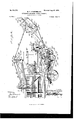
- FIG. 1 is a side elevation of the complete machine.
- Fig. 2 is anpelevation of the machine on the opposite side from Fig. 1 the dotted lines indicating the positions of the stacking mechanism when the same is folded upon the separator for transportation.
- Fig. 3 is a plan of the machine, the dotted lines indicating positions assu med by the stacking mechanism in swinging laterally of the sepa rator.
- FIG. 4 is a plan illustrating in detail the reversing mechanism whereby the stackin g mechanism is oscillated automat-icallylaterally of the separator, portions being broken away to reveal the'construction.
- Fig. 5 is a front end elevation illustrating in detail the mechanism shown in plan in Fig. 4.
- Fig. 6 is a side elevation of the rear end of the sep- Serial No. 713,306. (No model.)
- the numeral 1O designates a separator having the usual cylinder-shaft 11, with a belt-wheel 12 on one end thereof.
- a frame 13 is mounted horizontally on and projects from the end of the separator at which the straw is discharged and is located in the horizontal plane of the rear trucks of the separator.
- Standards 14 15-1617 are mounted on and rise from the frame 13, and antifriction-rollers 18 are pivoted on the upper ends of said standards, the standards being arranged at equal distances of separation.
- a turn-tablel9 is mounted horizontally and rests on the antifriction-rollers 18.
- a bed-frame 20 is mounted horizontally and secured by posts 20 to and upon the turntable 19
- a shaft21 is mounted for'rotationin bearings 22 23, rearwardly projecting from the rear corners of the bed-frame 20, and said shaft projects at both ends beyond its bearings.
- H in ge-plates 24: 25 are mounted for revolution on the projecting end portions of the shaft 21, and a stacker-frame is rigidly attached at its inner (lower) end to said hinge-plates.
- the stacker-frame is formed into sections 26 27,connected by hinges 28 29 in such a manner that the upper (outer) section 27 will fold for wardly and upon the lower (inner) section 26.
- Braces 30 31 are fixed to and project rearwardly and downwardly from the section 26 of the stacker-frame, and the outer extremities of said braces arein a plane between the ends of said section 26 of the frame.
- Braces 32 33 arefixed to and extend forwardly and downwardly from the section 27 ofthe stackerframe, and the extremities of said braces project beyond the hinged end of said section 27 and are arranged and so shaped as to abut the rearward extremities of the braces 30 31 and supportortruss thesectionsof the stackerframe in alinement with each other, as illustrated in Figs. 1,2, and 3 of the drawings.
- Ears 34 35 are fixed to and project downwardly from the extremities of the braces 30 31 and are formed with eyes or apertures, to which the rear ends' of cables 36 37 are attached.
- Sheaves are mounted in brackets 38 39 on the extremities of the braces 32
- Sheaves are mounted in brackets 40 41 on the extremities of the braces 30 31 adjacent the ears 34 35
- sheaves are mounted in brackets 42 43, fixed to the hinged ends of the section'26 of the stacker-frame, and the cables 36 37 extend from points of attachment to the ears and through said sheaves in sequence-that is to say, the cable 36 successively runs through the sheaves in the brackets 38 4O 42 and the cable 37 successively runs through the sheaves in the brackets 39 41 43.
- a socket 44 is mounted on and rises from the top of the rear end portion of the separator 1.0-and is braced to said separator by rods 45.
- a shaft 46 is stepped in the socket 44, and a cross-head 47 is rigidly mounted on the upper end of said shaft and extends transversely of the separator, the length of the cross-head being approximately the same as the width of the stacker-frame.
- Sheaves are mounted in brackets 48 49 on the upper face of the crosshead 47, and sheaves 5O 51 are mounted in a bracket'52, centrally located on the upper face of said cross-head between the brackets 48 '49.
- the cables 36 37 are run through the sheaves in the brackets 49 48 and thence through the sheaves 51 and extend forwardly in approximately parallel planes above the median line of the separator 10.
- a shaft 53 is mounted for rotation on a horizontal axis in bearings fixed to and rising from the separator 10 and extends transversely of said separator, one end portion of said shaft projecting beyond one side of the separator a material distance and having mounted thereon a worm-gear 54.
- a worm-shaft 55 having a worm 56 thereon and intermediate of its ends, is mounted for rotation on a vertical axis in bearings 57, fixed to and projecting laterally from the frame of the separator.
- the worm 56 meshes with the worm-gear 54 on the shaft 53, and hand-wheels 58 59 are fixed to the end portions of the worm-shaft 55, by means of which hand-wheels manual power may be applied to rotate the wormshaft and drive the drum-shaft 53 in either direction.
- Drums 6O 61 are mounted rigidly on the central portion of the drum-shaft 53,
- a bearing 62 is fixed to and rises from the top of the separator 10 between the adjacent ends of the drums 61.
- Levers 63 64 are fulcrumed at their lower ends on the bearings 22 23 and extend upwardly therefrom.
- Ears 65 66 are formed on and project outwardly from the forward ends of the bearings 22 23, and curved rods 67 68 are mounted rigidly by means of jamn'uts at their upper ends on the upper ends of the levers 63 6t, and the lower end portions of said curved rods extend through apertures in the cars 65 66 and are provided with split keys transversely mounted therein below said ears.
- Expansive coiled springs 69 70 are mounted on the curved rods 67 68 above the ears 65 66, and the tension of said springs is regulated and determined by adjusting-nuts 71 72 on the rods engaging the upper (outer) ends of the springs.
- Bearings 73 74 are mountedon and rise from the corners of the separater-frame laterally removed from the socket 44, and a rock-shaft 75 is mounted therein. The extremities of the rock-shaft 75 are bent rearwardly at right angles to the intermediate port-ion of said shaft and formed with hooks 76 77 at their outer ends.
- a crank-arm 78 is formed on and rises from the rock-shaft 75, adjacent the bearing-73, and a rod 79 is pivoted at one end to the extremity of said crankarm and extends therefrom forwardly of the separator, transverses a slide-bearin g 80, fixed to and rising from the separator adjacent the drum-shaft 53, and terminates in a handheld or eye 81.
- Angle-irons 82 83 are fixed to and extend forwardly and upwardly from the section 26 of the stacker-frame adjacent the upper (outer) end thereof and in such positions as to engage the hooks 76 77 of the rock-shaft 75 when the stacker-frame is swung forwardly for folding upon the separator.
- a shaft 84 is mounted for rotation in and transversely of the outer end of the section 27 of the stackerframe, and a shaft 85 is mounted for rotation in the lower corners of the bearings 24 25, extends transversely of the stacker-frame parallel with the shaft 84, and projects beyond one of its bearings.
- a bottom 86 is positioned in the stacker-frame, and an endless strawcarrier 87 is mounted for travel on the shafts within the stacker-frame and driven by the shaft 85, the cleats 88 of the straw-carrier traveling upwardly and outwardly in contact with the upper face of the bottom 86.
- a shaft 89 is mounted horizontally in and transversely of one end of the bed-frame 20, parallel with the shaft 21, and an endless straw-carrier 90 is mounted for travel on the shafts in the bedframe and driven by the shaft 21, the cleats 91 of the carrier 90 traveling rearwardly and outwardly in contact with a bottom 92 in said frame.
- a plate 93 is horizontally positioned on the central portion of the frame 13 and is centrally apertnred.
- a worm-gear 94 is stepped for revolution on the plate 93 concentric with the aperture in said plate and is located horizontally between the turn-table 19 and said plate.
- a shaft 95 is vertically positioned in the aperture in the center of the plate 93 and the turn-table 19, and a miter-- wheel 96 is mounted rigidly on the upper end of said shaft and the hub of said miter-wheel rests on a steel wear-plate 97, surmounting a boss 98 on the central portion of the turn-table.
- the bed-frame 20 is connected by the posts 20 rigidly to the turn table.
- Ears 99 100 are fixed to and rise from the turntable 19 and are apertured horizontally, and a shaft 101 is pivotally mounted in the apertures of the ears 99 100 and extends approximately radially of and from the turn-table 19 to a point beyond one side bar of the frame 13, and the outer end portion of said rock-shaft is provided with the crank-arm 102.
- crank-arm 102 to which a cable 103 is attached by one end, the cable 103 extending horizontally along the side bar of the frame 13, and thence through eyes 104, projecting from the stacker-frame to the outer (upper) end of said stacker-frame, at which point the cable is provided with a handhold or loop 105.
- a pawl 106 is fulcrumed at one end on one side bar of the frame 20 andis arranged and so shaped as to engage at times with the crankarm 102 on the rock-shaft 101 and limit the movement of oscillation of said shaft in one direction.
- a torsional coil spring '107 is mounted on the rock-shaft 101 between the cars 99 100, and a bifurcated crank-arm 108 on said shaft adjacent the ear 99 is engaged by one end of said spring, the opposite end of said spring engaging the turn-table 19 or a spoke thereof.
- the tension of the spring 107 tends to bear the bifurcated arm 108 downwardly and oscillate the rock-shaft in one direction and in a direction opposite to the movement that would be given the rockshaft bydraft of the cable 103.
- a pin 109 is mounted vertically in an aperture in the turntable 19 and engages normally in one or another of a series of apertures 110 in the wormgear 94.
- the pin 109 is formed with an annular groove near its upper end of such size as to receive the arms of the bifurcated crankarm 108.
- the pin 109 normally locks the turn-table 19 and worm-gear 94 together, but may be lifted away from the worm-gear by manual oscillation of the rock-shaft 101, either through draft applied to the cable 103 by an operator located on the straw-stack or at the discharge end of the stacker-frame or by an application of manual force directly to Upon the release of. the manual force applied to the rock-shaft the spring 107 will reverse the movement of said shaft and permit the seating of the pin 109 in one or another of the apertures or seats 110 inthe worm-gear.
- a curved crank-arm 111 is fixed to and projects forwardly from the rock-shaft 101 approximately parallel with the crank-arm, and it is the function of the arm 111 to oscillate the shaft automatically in the same direction that said shaft may be oscillated by manual force and such automatic movement is given by the engagement of the arm with one oranother of studs 112 113, fixed to and rising from bars 114 115 of the frame 13.
- a shaft 116 is mounted for rotation in bearings 117 118, fixed to the frame 13, and a sprocket-wheel 119 is rigidly mounted on one end of said shaft outside said frame.
- a shaft 120 is mounted for rotation in bearings fixed to the frame 13, and a sprocketwheel 121, rigidly mounted on said shaft, is connected by a chain 122 to the sprocketwheel119.
- a belt-wheel 123 is rigidly mounted on the outer end portion of the shaft 120 and connected by a belt 124 to the belt-wheel 12 on the cylindershaft 11.
- the shaft 120 extends nearly to the center of the frame 13, and a miter-gear 125 is mounted rigidly on the inner end thereof and meshes with a mitergear 126, rigidly mounted on the lower end of
- a counter-shaft 127 is counter-shaft 127 and connected by a chain 130 to a sprocket-wheel 131 on the shaft 21 adjacent the bearing 22.
- a sprocket-wheel 132 also mounted rigidly on the shaft 21, adjacent the sprocket-wheel 131, is connected by a chain 133 to a sprocket-wheel 134 on the extremity of the shaft 85
- the rotary movement of the cylinder-shaft 11 is communicated, through the belt-wheel 12, belt 124, belt-wheel 123, shaft 120, mitergear 125, miter-gear 126, shaft 95, miter-gear o 96, miter-gear 128, shaft 127, sprocket-wheel 129, chain 130, sprocket-wheel 131, shaft 21, sprocket-wheel132, chain 133, sprocket-wheel 134, and shaft85, to and drives the strawcarrier 87 in the stackerframe.
- municated, as described, to the shaft 21, drives the straw-carrier in the bed-frame 20 in the same direction as the straw-carrier in the stacker-frame is driven.
- chain and wheel connection between the shaft 120 and the shaft 116 drives said shaft 116 in the same direction as the cylinder-shaft is driven and in the direction of the arrow C6111 Fig. 5.
- 136 is formed with a clutch member arranged and so shaped as to engage at times with one face of a clutch member 138, slidably mounted on the worm-shaft 137.
- the clutch member 138 is formed with a longitudinal that is traversed by a pin 140, seated in and projecting radially from the worm-shaft.
- lever 141 bifurcated at its rear end, is fulcrumed at its forward end on the frame 13
- a miter-gear 128 is mounted rigidly 75
- the sprocket A gear-wheel 135 is mounted rigidly
- the hub of the gear-wheel I 10 beneath the peripheral portion of the turnme table 19, and the bifurcated end portion of said lever embraces the clutch member 138 and is confined by peripheral flanges 142 143 on said clutch member.
- clutch member 138 mounted to rotate with the worm- 1 2 shaft 137 and slide upon and longitudinally of said shaft under the control of the lever 141, engaging one or another of the peripheral flanges 142 143.
- a clutch member 144 is mounted loosely on the worm-shaft 137 and rigidly connected to a sleeve 145 to a gearwheel 146, mounted loosely on the wormshaft adjacent the bearing 118.
- the gearwheel 146 meshes with a gear-wheel 147,
- the clutch member 144 is so shaped and arranged as to engage at times with one
- a worm 149 is mounted rigidly on the inner end portion of the worm-shaft 137, the gear-wheel 146 and worm being located on opposite sides of the bearing 118. It may be well to observe here that the worm 149 meshes with and drives the'worm-gear 94, and the bearing 118 limits thelongitudinal movementof the worm and its shaft.
- the tripping-lever 152 is formed with a lateral bend or crank 155 in its upper portion, and a rod 156 is pivotally connected at one end to said lateral bend or crank, and said rod is connected at its opposite end to the lever 141, adjacent the bifurcated end portion of said 1ever.
- a pin 157 vertically mounted in one or another of the aper tures 15l,en gages the arm of the tripping-lever 152, reversely moves said lever, and, operatin g through the bend or crank 155 and rod 156 pushes the lever 141 and clutch member 138 away from the clutch member 144 and toward the gear-wheel 136, thus restablishing the original movement of oscillation or rotary travel of the stacker frame.
- a crank arm 158 projects laterally from the tripping lever 152 and is connected by a retractile coilspring 159 to an adjusting-screw 160, seated in one side bar of the frame 13.
- the relative positions of the tripping-lever and adjustingscrew are such that the spring 159 tends to retain the tripping-lever in either position, at either limit of rotary movement, in which it may be placed by contact of one or another of the traveling pins 150 157.
- the pins 150 157 may be removed from or replaced in the apertures. or seats 151, as desired, to govern and control the degree of movementof oscillation of the stacker-frame between the operations of reversing such movement or to determine the degree of oscillation of the stacker-frame laterallyof and relative to the median line of the separator.
- bearings 162 are fixed to anddepend from the lower margin of the hood 161, andahingerod is extended through and horizontallysupported by said bearings.
- a plurality of leaves or wings 163 are mounted upon, hinged to, and depend from'the hinge-rod in the bearings 162 in close relations with each other and abutting each other side by side.
- the leaves or wings 163 are arranged to swing outwardly relative to the hood 161 and permit the discharge of the straw upon the carrier 90, while at the same time they shield the straw and chad from the influence of air-currents that otherwise might scatter said straw and chaff and prevent the discharge thereof by the straw-carriers.
- Hangers 164 165 are pivoted at their upper ends upon and depend from the rear portion of the separator-frame adjacent the ends of the hood 161, and a failings-frame 166 is hung with its rear corners on the lower ends of said hangers.
- Bearings 167 168 are fixed to the forward corners of the tailings-frame 166, and a rock-shaft 169 is mounted with its central (straight) body portion in a horizontal position beneath and transversely of the forward end of the tailings-frame and embraced by bifurcations or forks on and extending downwardly from the bearings 167 168.
- Crank-arms 170 171 are formed on and extend downwardly from the rock-shaft 169 and are bent laterally and journaled in bearings 172 17 3,proj ecting rearwardly from the separatorframe.
- Thus is the rock-shaft journaled for oscillation in the bearings 172 173 and carries the forward end of the tailings-frame, the rear end of the tailings-frame being suspended by the hangers 164 165 loosely.
- Au extension 174 is formed on and projects downwardly from the crank-arm 170 and is bent inwardly at its lower end.
- a pitman 175 is pivotally connected at its inner end to the inwardly-extending portion of the extension 174 of the crank-arm 170 and extends rearwardly therefrom to and is pivotally connected with a wrist-pin 176, mounted on a gearwheel 177, journaled on a stud 178, laterally projecting from a side bar of the frame 13, adjacent the sprocket-wheel121 on the shaft 120.
- the gear-Wheel 177 meshes with a gearwheel 178, rigidly mounted on the shaft 120 between the sprocket-wheel121 and the frame 13.
- a rock-shaft 179 is mounted in the bearings 167 168, extends transversely of the forward end of the tailings-frame, and has a blade or wing 180 mounted rigidly on one side of the tailings-frame.
- a crank-arm 181 is formed. on one end of the rock-shaft 179, extends rearwardly at right angles to said shaft, and has its rear end portion turned inwardly and so shaped and arranged as to seat in one or another of apertures 182 in a plate 183, fixed to
- a solid bottom 184 is mounted in the tailings-frame and projects forwardly into the fanchamber of the separator. is mounted in the failings-frame immediately above and spaced apart from the solid bottom 184, and a series of ribs 185, of ratchet formation, are mounted on the screen and extend transversely of the tailings-frame.
- the tailin gs of chaff and grain that are blown from the fan-chamber upon the tailings-frame are sifted thereby, the chaff going rearwardly over the ribs and upon the carrier 90 and the grain falling through the screen upon the solid bottom 184 and discharging back into the fan-chamber, below the main current of air therefrom.
- the rock-shaft 179, blade 180, crank 181, and perforated plate 183 I am enabled to control, regulate, and determine the strength and direction of the current of air proceeding from the fanchamber of the separator over the tailingsframe.
- Shields 186 187 are mounted on and extend upwardly from opposite sides .of the bedframe 20 and serve to retain the straw against lateral displacement from the carrier 90.
- the stacker-frame may be folded upon the separator, as shown by dotted lines in Fig. 2, by the following operation: Manual force is applied to one or another of the hand-wheels 58 59 to rotate the worm 56.
- the Worm 56 engages and rotates .wormgear 54 toeffect the rotation of the worm-shaft 53 and drums 61 thereon.
- the drums receive and wind up the forward end portions of the cables 36 37, and said cables, drawing through the sheaves on the crosshead 47, lift the stacker-frame on the axis of rotation of the shaft 21.
- the movement of rotation of the wormshaft 55 is reversed, thus slackening the cables and permitting the section 27 of the stacker-frame to descend gradually and under perfect control to a position of rest upon the top of the separator, the cables paying out through the sheaves on the stacker-frame and permitting the separation of the meeting A perforated slide or screen IIO ends of the braces 30 31 32 33, the section 27 of the frame swinging on the pins of the hinges 28 29.
- the worm mechanism is operated to first lift the section 27 of the frame by draft upon the cables 36 37 until the braces of the frame contact, and.
- the stacker-frame may be adjusted in any position between a horizontal plane and the vertical plane for use; but its operation will be more satisfactory when inclined to less than sixty degrees than it inclined to a greater extent than sixty degrees relative to a horizontal plane.
- the cylinder-shaft 11 of the separator may be driven in any desired manner.
- a stacker-frame formed in two sections hinged together, truss rods depending from and meeting below the sections of the stackerframe, whereby flexure of said frame in one direction is limited and cables mounted on and connecting the sections of the frame and truss-rods, substantially as described.
- the stacker-frame formed in two sections hinged together, buffer-arms 63, 64 arranged for engagement by the stacker-frame, springs supporting said bntferarms, angle-irons on one section of the stacker-frame, releasable hooks arranged to engage said angle-irons and hold the stacker-frame against the resilience of the buffer-arms and rope and Windlass mechanism whereby the sections of the stacker-frame may be flexed or extended during the engagement of the hooks with the angle-irons.
- the frame 13 the worm-gear mounted for revolution on said frame, the reversible mechanism whereby said worm-gear is revolved, the turntable mounted parallel with the worm-gear and latched thereto, the tripping-lever mount ed for oscillation and connected with the re versible mechanism and pins mounted upon the turn-table and arranged for alternate engagement with the tripping-lever.
- the frame 13 the worm-gear mounted for revoln tion on said frame, the turn-table mounted parallel with the worm-gear, the pin connect ing said gear and turn-table, the rock-shaft mounted for oscillation on the turn-table, spring-pressed in one direction and arranged for manual operation in the other direction, studs on the frame and a crank-arm on said rock-shaft so shaped and arranged as to engage one or the other of said studs and move the rock-shaft in the direction of the manual operation thereof.
Landscapes
- Engineering & Computer Science (AREA)
- Mechanical Engineering (AREA)
- Structure Of Transmissions (AREA)
Description
No. 652,148. Patented June l9, I900.
M. F. STADTMULLEB. ATTACHED SWINGING STB AW STACKER.
. (Application filed Apr 17, 1899.) (No Model.) 5 Sheets-Sheet I.
QR Q .m VQM Tiff o E inn THE NORRIS PETERS co Pam-060 0., wnsuwo'ron, n. cv
m. 652,!48. Patented 1m l9. I900.
m. \F. STADTMULLER.
ATTACHED SWINGING STBAW'STACKE'R.
(Applicatipn filed Apr. 17, 1899.) (No Model.) 5 Sheets-Sheet 2.
LEW 727 Nu. 652,!48. Patented. June l9, I900.
M. F. STADTMULLER.
ATTACHED SWINGING STRAW STAGKER.
(Application fil ed Apr. 17, 1899.) (No Model.) 5 Sheets-Sheet 3.
m: "cams versus co.. woTo-u'rua, WASNINGTON. o. c.
No. 652,148. Patented June l9, I900.
M. F. STADTMU'LLER.. ATTACHED SWINGINGSTRAW STACKER.
(Application filed Apr. 17 1898.) 1
5 Sheats-$heet 4.
(No Model.
Iii)! No. 652,!48. Patented lune l9, moo.
m. F. STADTMI1LLER.
ATTACHED SWINGING STRAW" STAOKER.
(Application filed Apr. 17, 1899.) (No Model.) 5 Sheets-Sheet 5.
ZJJ
THE uoams PETERS co PHOTOUTHD" WASmNOTOm 11c.
- means tooassistmaterially in'unfolding the "l ES MAX F. STADTMULLER ATTACHED SWINGIN or POMEROY, IOWA.
G 'STRAW-STACKER.
SPECIFICATION forming part of Letters Patent No. 652,148, dated June 19, 1900.
Application filed April 1 7, 1399.
T aZZ whom it may concern:
Be it known that 1, MAX I STADTMULLER, a citizen of the United States of America, and a resident of Pomeroy, Calhoun county; Iowa, have invented certain'new and useful Improvements in Attached Swinging Straw- S tackers, of which the following is a specification.
The object of this invention is to provide improved means for stacking straw. i
This invention has relation to stacker attachments for separators, and has for its objects to combine with the sectional, fold able, and adjustable stacker novel means, for strengthening and holding the sections of the stacker in alinement; adjusting mechanism cooperating with the stacker and itsbracing stacker, maintaining its sections in alinement when unfolded, and raising and lowering the outer end of the stacker; mechanism for oscillating, locking, andreleasing-the stacker, and means for relieving the shock incident to folding of the stacker, all the adjunct-ive parts being combined and arranged with a view to economy of space, positiveness of action, ease of operation, and accessibility for any desired purpose. H
The invention further consists of the novel features, details of construction, and combi nations of the parts, which will hereinafter. be more fully set-forth, claimed, and illus: trated in the accompanying drawings, in which j v Figure 1 is a side elevation of the complete machine. Fig. 2 is anpelevation of the machine on the opposite side from Fig. 1 the dotted lines indicating the positions of the stacking mechanism when the same is folded upon the separator for transportation. Fig. 3 is a plan of the machine, the dotted lines indicating positions assu med by the stacking mechanism in swinging laterally of the sepa rator. Fig. 4 isa plan illustrating in detail the reversing mechanism whereby the stackin g mechanism is oscillated automat-icallylaterally of the separator, portions being broken away to reveal the'construction. Fig. 5 is a front end elevation illustrating in detail the mechanism shown in plan in Fig. 4. Fig. 6 is a side elevation of the rear end of the sep- Serial No. 713,306. (No model.)
arator, the inner end of the stacker, and the cooperating mechanism on a larger scale.
In the construction, mounting, and operation of the machine, as illustrated, the numeral 1O designates a separator having the usual cylinder-shaft 11, with a belt-wheel 12 on one end thereof. A frame 13 is mounted horizontally on and projects from the end of the separator at which the straw is discharged and is located in the horizontal plane of the rear trucks of the separator. Standards 14 15-1617 are mounted on and rise from the frame 13, and antifriction-rollers 18 are pivoted on the upper ends of said standards, the standards being arranged at equal distances of separation. A turn-tablel9 is mounted horizontally and rests on the antifriction-rollers 18. A bed-frame 20 is mounted horizontally and secured by posts 20 to and upon the turntable 19 A shaft21 is mounted for'rotationin bearings 22 23, rearwardly projecting from the rear corners of the bed-frame 20, and said shaft projects at both ends beyond its bearings. H in ge-plates 24: 25 are mounted for revolution on the projecting end portions of the shaft 21, and a stacker-frame is rigidly attached at its inner (lower) end to said hinge-plates. The stacker-frame is formed into sections 26 27,connected by hinges 28 29 in such a manner that the upper (outer) section 27 will fold for wardly and upon the lower (inner) section 26. Braces 30 31 are fixed to and project rearwardly and downwardly from the section 26 of the stacker-frame, and the outer extremities of said braces arein a plane between the ends of said section 26 of the frame. Braces 32 33 arefixed to and extend forwardly and downwardly from the section 27 ofthe stackerframe, and the extremities of said braces project beyond the hinged end of said section 27 and are arranged and so shaped as to abut the rearward extremities of the braces 30 31 and supportortruss thesectionsof the stackerframe in alinement with each other, as illustrated in Figs. 1,2, and 3 of the drawings. Ears 34 35 are fixed to and project downwardly from the extremities of the braces 30 31 and are formed with eyes or apertures, to which the rear ends' of cables 36 37 are attached.
Sheaves are mounted in brackets 38 39 on the extremities of the braces 32 Sheaves are mounted in brackets 40 41 on the extremities of the braces 30 31 adjacent the ears 34 35, and sheaves are mounted in brackets 42 43, fixed to the hinged ends of the section'26 of the stacker-frame, and the cables 36 37 extend from points of attachment to the ears and through said sheaves in sequence-that is to say, the cable 36 successively runs through the sheaves in the brackets 38 4O 42 and the cable 37 successively runs through the sheaves in the brackets 39 41 43. A socket 44 is mounted on and rises from the top of the rear end portion of the separator 1.0-and is braced to said separator by rods 45. A shaft 46 is stepped in the socket 44, and a cross-head 47 is rigidly mounted on the upper end of said shaft and extends transversely of the separator, the length of the cross-head being approximately the same as the width of the stacker-frame. Sheaves are mounted in brackets 48 49 on the upper face of the crosshead 47, and sheaves 5O 51 are mounted in a bracket'52, centrally located on the upper face of said cross-head between the brackets 48 '49. The cables 36 37 are run through the sheaves in the brackets 49 48 and thence through the sheaves 51 and extend forwardly in approximately parallel planes above the median line of the separator 10. A shaft 53 is mounted for rotation on a horizontal axis in bearings fixed to and rising from the separator 10 and extends transversely of said separator, one end portion of said shaft projecting beyond one side of the separator a material distance and having mounted thereon a worm-gear 54. A worm-shaft 55, having a worm 56 thereon and intermediate of its ends, is mounted for rotation on a vertical axis in bearings 57, fixed to and projecting laterally from the frame of the separator. The worm 56 meshes with the worm-gear 54 on the shaft 53, and hand-wheels 58 59 are fixed to the end portions of the worm-shaft 55, by means of which hand-wheels manual power may be applied to rotate the wormshaft and drive the drum-shaft 53 in either direction. Drums 6O 61 are mounted rigidly on the central portion of the drum-shaft 53,
andthe forward end portions of the cables 36 37 are fixed to and adapted to be wound upon said drums. A bearing 62 is fixed to and rises from the top of the separator 10 between the adjacent ends of the drums 61. Levers 63 64 are fulcrumed at their lower ends on the bearings 22 23 and extend upwardly therefrom. Ears 65 66 are formed on and project outwardly from the forward ends of the bearings 22 23, and curved rods 67 68 are mounted rigidly by means of jamn'uts at their upper ends on the upper ends of the levers 63 6t, and the lower end portions of said curved rods extend through apertures in the cars 65 66 and are provided with split keys transversely mounted therein below said ears. Expansive coiled springs 69 70 are mounted on the curved rods 67 68 above the ears 65 66, and the tension of said springs is regulated and determined by adjusting-nuts 71 72 on the rods engaging the upper (outer) ends of the springs. Bearings 73 74 are mountedon and rise from the corners of the separater-frame laterally removed from the socket 44, and a rock-shaft 75 is mounted therein. The extremities of the rock-shaft 75 are bent rearwardly at right angles to the intermediate port-ion of said shaft and formed with hooks 76 77 at their outer ends. A crank-arm 78 is formed on and rises from the rock-shaft 75, adjacent the bearing-73, and a rod 79 is pivoted at one end to the extremity of said crankarm and extends therefrom forwardly of the separator, transverses a slide-bearin g 80, fixed to and rising from the separator adjacent the drum-shaft 53, and terminates in a handheld or eye 81. Angle-irons 82 83 are fixed to and extend forwardly and upwardly from the section 26 of the stacker-frame adjacent the upper (outer) end thereof and in such positions as to engage the hooks 76 77 of the rock-shaft 75 when the stacker-frame is swung forwardly for folding upon the separator. A shaft 84 is mounted for rotation in and transversely of the outer end of the section 27 of the stackerframe, and a shaft 85 is mounted for rotation in the lower corners of the bearings 24 25, extends transversely of the stacker-frame parallel with the shaft 84, and projects beyond one of its bearings. A bottom 86 is positioned in the stacker-frame, and an endless strawcarrier 87 is mounted for travel on the shafts within the stacker-frame and driven by the shaft 85, the cleats 88 of the straw-carrier traveling upwardly and outwardly in contact with the upper face of the bottom 86. A shaft 89 is mounted horizontally in and transversely of one end of the bed-frame 20, parallel with the shaft 21, and an endless straw-carrier 90 is mounted for travel on the shafts in the bedframe and driven by the shaft 21, the cleats 91 of the carrier 90 traveling rearwardly and outwardly in contact with a bottom 92 in said frame. A plate 93 is horizontally positioned on the central portion of the frame 13 and is centrally apertnred. A worm-gear 94 is stepped for revolution on the plate 93 concentric with the aperture in said plate and is located horizontally between the turn-table 19 and said plate. A shaft 95 is vertically positioned in the aperture in the center of the plate 93 and the turn-table 19, and a miter-- wheel 96 is mounted rigidly on the upper end of said shaft and the hub of said miter-wheel rests on a steel wear-plate 97, surmounting a boss 98 on the central portion of the turn-table. As hereinbefore stated, the bed-frame 20 is connected by the posts 20 rigidly to the turn table. Ears 99 100 are fixed to and rise from the turntable 19 and are apertured horizontally, and a shaft 101 is pivotally mounted in the apertures of the ears 99 100 and extends approximately radially of and from the turn-table 19 to a point beyond one side bar of the frame 13, and the outer end portion of said rock-shaft is provided with the crank-arm 102.
a crank-arm 102, to which a cable 103 is attached by one end, the cable 103 extending horizontally along the side bar of the frame 13, and thence through eyes 104, projecting from the stacker-frame to the outer (upper) end of said stacker-frame, at which point the cable is provided with a handhold or loop 105. A pawl 106 is fulcrumed at one end on one side bar of the frame 20 andis arranged and so shaped as to engage at times with the crankarm 102 on the rock-shaft 101 and limit the movement of oscillation of said shaft in one direction. A torsional coil spring '107 is mounted on the rock-shaft 101 between the cars 99 100, and a bifurcated crank-arm 108 on said shaft adjacent the ear 99 is engaged by one end of said spring, the opposite end of said spring engaging the turn-table 19 or a spoke thereof. The tension of the spring 107 tends to bear the bifurcated arm 108 downwardly and oscillate the rock-shaft in one direction and in a direction opposite to the movement that would be given the rockshaft bydraft of the cable 103. A pin 109 is mounted vertically in an aperture in the turntable 19 and engages normally in one or another of a series of apertures 110 in the wormgear 94. The pin 109 is formed with an annular groove near its upper end of such size as to receive the arms of the bifurcated crankarm 108. The pin 109 normally locks the turn-table 19 and worm-gear 94 together, but may be lifted away from the worm-gear by manual oscillation of the rock-shaft 101, either through draft applied to the cable 103 by an operator located on the straw-stack or at the discharge end of the stacker-frame or by an application of manual force directly to Upon the release of. the manual force applied to the rock-shaft the spring 107 will reverse the movement of said shaft and permit the seating of the pin 109 in one or another of the apertures or seats 110 inthe worm-gear. A curved crank-arm 111 is fixed to and projects forwardly from the rock-shaft 101 approximately parallel with the crank-arm, and it is the function of the arm 111 to oscillate the shaft automatically in the same direction that said shaft may be oscillated by manual force and such automatic movement is given by the engagement of the arm with one oranother of studs 112 113, fixed to and rising from bars 114 115 of the frame 13. A shaft 116 is mounted for rotation in bearings 117 118, fixed to the frame 13, and a sprocket-wheel 119 is rigidly mounted on one end of said shaft outside said frame. A shaft 120 is mounted for rotation in bearings fixed to the frame 13, and a sprocketwheel 121, rigidly mounted on said shaft, is connected by a chain 122 to the sprocketwheel119. A belt-wheel 123 is rigidly mounted on the outer end portion of the shaft 120 and connected by a belt 124 to the belt-wheel 12 on the cylindershaft 11. The shaft 120 extends nearly to the center of the frame 13, and a miter-gear 125 is mounted rigidly on the inner end thereof and meshes with a mitergear 126, rigidly mounted on the lower end of A counter-shaft 127 is counter-shaft 127 and connected by a chain 130 to a sprocket-wheel 131 on the shaft 21 adjacent the bearing 22. A sprocket-wheel 132, also mounted rigidly on the shaft 21, adjacent the sprocket-wheel 131, is connected by a chain 133 to a sprocket-wheel 134 on the extremity of the shaft 85 adjacent thereto.
The rotary movement of the cylinder-shaft 11 is communicated, through the belt-wheel 12, belt 124, belt-wheel 123, shaft 120, mitergear 125, miter-gear 126, shaft 95, miter-gear o 96, miter-gear 128, shaft 127, sprocket-wheel 129, chain 130, sprocket-wheel 131, shaft 21, sprocket-wheel132, chain 133, sprocket-wheel 134, and shaft85, to and drives the strawcarrier 87 in the stackerframe.
municated, as described, to the shaft 21, drives the straw-carrier in the bed-frame 20 in the same direction as the straw-carrier in the stacker-frame is driven. chain and wheel connection between the shaft 120 and the shaft 116 drives said shaft 116 in the same direction as the cylinder-shaft is driven and in the direction of the arrow C6111 Fig. 5. on the shaft 116 adjacent to and just inside of one side bar of the frame 13 and meshes with a gear-wheel 136, loosely mounted on a worm-shaft 137, mounted for rotation in the bearings 117 118. 136 is formed with a clutch member arranged and so shaped as to engage at times with one face of a clutch member 138, slidably mounted on the worm-shaft 137. The clutch member 138 is formed with a longitudinal that is traversed by a pin 140, seated in and projecting radially from the worm-shaft. lever 141, bifurcated at its rear end, is fulcrumed at its forward end on the frame 13 A miter-gear 128 is mounted rigidly 75 The same rotary movement of the cylinder-shaft, com- The sprocket A gear-wheel 135 is mounted rigidly The hub of the gear-wheel I 10 beneath the peripheral portion of the turnme table 19, and the bifurcated end portion of said lever embraces the clutch member 138 and is confined by peripheral flanges 142 143 on said clutch member. Thus is the clutch member 138 mounted to rotate with the worm- 1 2 shaft 137 and slide upon and longitudinally of said shaft under the control of the lever 141, engaging one or another of the peripheral flanges 142 143. A clutch member 144 is mounted loosely on the worm-shaft 137 and rigidly connected to a sleeve 145 to a gearwheel 146, mounted loosely on the wormshaft adjacent the bearing 118. The gearwheel 146 meshes with a gear-wheel 147,
of the faces of the clutch member 138.
mounted on a stud projecting from the bearing 118 immediately below the worm-shaft 137, and the gear-wheel 147 meshes with the gear-wheel148 on the inner end portion of the shaft 116, the gear148 and miter-gear being located on opposite sides of the bearing 118. The clutch member 144 is so shaped and arranged as to engage at times with one A worm 149 is mounted rigidly on the inner end portion of the worm-shaft 137, the gear-wheel 146 and worm being located on opposite sides of the bearing 118. It may be well to observe here that the worm 149 meshes with and drives the'worm-gear 94, and the bearing 118 limits thelongitudinal movementof the worm and its shaft. When the clutch member 138 is in the position shown in Figs. 4 and 5, engaging the clutch member on the hub of the gear-wheel 136, a driving connection is established between the gears 136, clutch members, and Worm-shaft 137, whereby said worm-shaft is rotated in the direction of the arrows bin Fig. 4, resulting in a movement of revolution of the worm-gear 94 in the direction of the arrow 0 in Fig. 4, whereby the worm-gear, turntable 19, connected thereto by the pin 109, bed-frame 20, and mechanism carried by said bed-frame and including the stacker frame are revolved in such a manner as to carry the stacker-frame in an arc toward and over the belt-Wheel 123 of the driving mechanism and into a position nearly at right angles to the longitudinal plane of the separator. When the limit of movement in the direction just described has been reached, a pin 150, vertically seated in one or another of a series of apertures 151 in the peripheral portion of the turn-table, engages the arm of a tripping-lever 152, vertically positioned for oscillation in bearings 153 154, fixed to the frame13, and moves said lever in one direction. The tripping-lever 152 is formed with a lateral bend or crank 155 in its upper portion, and a rod 156 is pivotally connected at one end to said lateral bend or crank, and said rod is connected at its opposite end to the lever 141, adjacent the bifurcated end portion of said 1ever. When the pin engages the arm of the tripping-lever and oscillates said lever in the direction of travel of the pin, such movement of oscillation is communicated through the bend or crank of the lever and exerts a draft on the rod 156, resulting in a movement of the lever 141 into engagement with the peripheral flange 143 of the clutch member 138, whereby said clutch member 138 is reciprocated or moved longitudinally on the worm-shaft in such a manner as to release the engagement thereof from the hub of the gear- Wheel136 and establish an engagement between the other end of the clutch member and the clutch-face of the member 144. When the clutch member 138 is shifted into contact with the clutch member 144, the gear-wheel 136 runs idly, and the motion heretofore transmitted idly from the shaft 116 through the gear-wheels 148 147 146 now becomes a driving motion, and owing to the interposition of the gear-wheel 147 between the gears of the shafts the motion of the worm-shaft 137 is reversed relative to its prior motion, thus providing for a reversal of the movement of revolution of the worm-gear 94 and turn-table. The reverse movement of the turn-table and mechanism carried thereon is continued until the stacker-frame is swung laterally of the separator and projects from the side of the frame 13 opposite to the belt wheel 123. When limit of desired movement in the reversed direction is reached, a pin 157, vertically mounted in one or another of the aper tures 15l,en gages the arm of the tripping-lever 152, reversely moves said lever, and, operatin g through the bend or crank 155 and rod 156 pushes the lever 141 and clutch member 138 away from the clutch member 144 and toward the gear-wheel 136, thus restablishing the original movement of oscillation or rotary travel of the stacker frame. A crank arm 158 projects laterally from the tripping lever 152 and is connected by a retractile coilspring 159 to an adjusting-screw 160, seated in one side bar of the frame 13. The relative positions of the tripping-lever and adjustingscrew are such that the spring 159 tends to retain the tripping-lever in either position, at either limit of rotary movement, in which it may be placed by contact of one or another of the traveling pins 150 157. The pins 150 157 may be removed from or replaced in the apertures. or seats 151, as desired, to govern and control the degree of movementof oscillation of the stacker-frame between the operations of reversing such movement or to determine the degree of oscillation of the stacker-frame laterallyof and relative to the median line of the separator. It may occur that one or another of the pins 150 1.57 will be accidentally displaced from its seat, and to avoid crashing the stacker-frame or driving mechanism into the frame of the separator I have provided the crank-arm 111 and studs 112 113, in the use of which the crankarm 111 will ride upon one orthe other of the studs and release the locking engagement of the pin 109 between the turn-table and wormgear in the event that for any reason the tripping-lever fails to reverse the driving mechanism whereby the worm-gear and turntable are revolved. Again, it sometimes occurs that it is desirable to stop the oscillatory movement of the stacker-frame to deposit a greater quantity of straw in a given position, and for this reason I have provided the crank-arm 102, cable 103, handhold 105, and pawl 106, the operations of which hereinbefore have been explained. In the oscillation of the stacker-frame laterally the crosshead 47 oscillates inits step and compensates for the slackening and tightening of the cables 36 37 intermediate of their ends and maintains a level transversely positioning of A hood 161, preferably the stacker-frame.
formed of sheet metal, is mounted rigidly upon and projects rearwardly from the strawdischarging end of the separator and is supported in its central portion by one of the braces 45, connecting it to the socket 44. Bearings 162 are fixed to anddepend from the lower margin of the hood 161, andahingerod is extended through and horizontallysupported by said bearings. A plurality of leaves or wings 163 are mounted upon, hinged to, and depend from'the hinge-rod in the bearings 162 in close relations with each other and abutting each other side by side. The leaves or wings 163 are arranged to swing outwardly relative to the hood 161 and permit the discharge of the straw upon the carrier 90, while at the same time they shield the straw and chad from the influence of air-currents that otherwise might scatter said straw and chaff and prevent the discharge thereof by the straw-carriers. Hangers 164 165 are pivoted at their upper ends upon and depend from the rear portion of the separator-frame adjacent the ends of the hood 161, and a failings-frame 166 is hung with its rear corners on the lower ends of said hangers. Bearings 167 168 are fixed to the forward corners of the tailings-frame 166, and a rock-shaft 169 is mounted with its central (straight) body portion in a horizontal position beneath and transversely of the forward end of the tailings-frame and embraced by bifurcations or forks on and extending downwardly from the bearings 167 168. Crank-arms 170 171 are formed on and extend downwardly from the rock-shaft 169 and are bent laterally and journaled in bearings 172 17 3,proj ecting rearwardly from the separatorframe. .Thus is the rock-shaft journaled for oscillation in the bearings 172 173 and carries the forward end of the tailings-frame, the rear end of the tailings-frame being suspended by the hangers 164 165 loosely. Au extension 174 is formed on and projects downwardly from the crank-arm 170 and is bent inwardly at its lower end. A pitman 175 is pivotally connected at its inner end to the inwardly-extending portion of the extension 174 of the crank-arm 170 and extends rearwardly therefrom to and is pivotally connected with a wrist-pin 176, mounted on a gearwheel 177, journaled on a stud 178, laterally projecting from a side bar of the frame 13, adjacent the sprocket-wheel121 on the shaft 120. The gear-Wheel 177 meshes with a gearwheel 178, rigidly mounted on the shaft 120 between the sprocket-wheel121 and the frame 13. The rotary motion of the shaft 120 is communicated through the gear-wheel 178, gear-wheel177, wrist-pin 176, pitman 175', and extension 174 and converted thereby to effect the oscillation of the rock-shaft 17 0, whereby the tailiugs-frame may be rectilinearly 1'eciprocated. A rock-shaft 179 is mounted in the bearings 167 168, extends transversely of the forward end of the tailings-frame, and has a blade or wing 180 mounted rigidly on one side of the tailings-frame.
and extending rearwardly and upwardly therefrom. A crank-arm 181 is formed. on one end of the rock-shaft 179, extends rearwardly at right angles to said shaft, and has its rear end portion turned inwardly and so shaped and arranged as to seat in one or another of apertures 182 in a plate 183, fixed to A solid bottom 184 is mounted in the tailings-frame and projects forwardly into the fanchamber of the separator. is mounted in the failings-frame immediately above and spaced apart from the solid bottom 184, and a series of ribs 185, of ratchet formation, are mounted on the screen and extend transversely of the tailings-frame. The tailin gs of chaff and grain that are blown from the fan-chamber upon the tailings-frame are sifted thereby, the chaff going rearwardly over the ribs and upon the carrier 90 and the grain falling through the screen upon the solid bottom 184 and discharging back into the fan-chamber, below the main current of air therefrom. By means of the rock-shaft 179, blade 180, crank 181, and perforated plate 183 I am enabled to control, regulate, and determine the strength and direction of the current of air proceeding from the fanchamber of the separator over the tailingsframe.
Shields 186 187 are mounted on and extend upwardly from opposite sides .of the bedframe 20 and serve to retain the straw against lateral displacement from the carrier 90.
Assuming the parts to be positioned as shown in Fig. 1, the stacker-frame may be folded upon the separator, as shown by dotted lines in Fig. 2, by the following operation: Manual force is applied to one or another of the hand-wheels 58 59 to rotate the worm 56. The Worm 56 engages and rotates .wormgear 54 toeffect the rotation of the worm-shaft 53 and drums 61 thereon. The drums receive and wind up the forward end portions of the cables 36 37, and said cables, drawing through the sheaves on the crosshead 47, lift the stacker-frame on the axis of rotation of the shaft 21. In the elevation of the stacker-frame the side bars thereof contact With the levers 63 64 and are steadied and restrained in further forward movement by said levers cushioning upon the springs 69 and yielding under the draft of the cables only and not affected materially by the forwardlytrending weight of the stacker frame. In its forward movement the stacker frame approaches the hood 161 and the angleirons 82 83 travel beneath and engage the hooks 76 77 on the rock-shaft 75. At this time the movement of rotation of the wormshaft 55 is reversed, thus slackening the cables and permitting the section 27 of the stacker-frame to descend gradually and under perfect control to a position of rest upon the top of the separator, the cables paying out through the sheaves on the stacker-frame and permitting the separation of the meeting A perforated slide or screen IIO ends of the braces 30 31 32 33, the section 27 of the frame swinging on the pins of the hinges 28 29. When it is desired to elevate and extend the stackerframe, the worm mechanism is operated to first lift the section 27 of the frame by draft upon the cables 36 37 until the braces of the frame contact, and. then the hooks 76 77 of the rock-shaft 75 are released from the angle-irons 82 83 by manual operation of the draw-rod 79, acting through the crank-arm 7 6 to oscillate said rock-shaft, and then the expansive resilience of the springs 69 impels the stacker-frame rearwardly, subject to a succeeding manual relaxation of the cables 36 37, until. the desired degree of inclination of the stackerframe is attained. The stacker-frame may be adjusted in any position between a horizontal plane and the vertical plane for use; but its operation will be more satisfactory when inclined to less than sixty degrees than it inclined to a greater extent than sixty degrees relative to a horizontal plane. The cylinder-shaft 11 of the separator may be driven in any desired manner.
I claim as my invention- 1. In a machine of the class described, a stacker-frame formed in two sections hinged together, truss rods depending from and meeting below the sections of the stackerframe, whereby flexure of said frame in one direction is limited and cables mounted on and connecting the sections of the frame and truss-rods, substantially as described.
2. In combination with the sectional stacker having its sections hinged, a sectional truss having its parts secured to the respective hinged sections of the stacker and having their abutting ends out of line with the joint between the hinged extremities of the stackersections, and cables connecting the sections of the stacker-frame and truss adjacent to their abutting or meeting ends, substantially as specified.
3. The combination of the separator, the drum-shaft thereon, means for driving the drum-shaft, a stacker-frame mounted for vertical adjustment and horizontal oscillation, cables connecting said stackerframe and drum-shaft, a cross-head pivoted at its center upon said separator, sheaves on the end portions of said cross-head and receiving the cables from the stacker-frame, and sheaves on the central portion of said cross-head and receiving said cables from the sheaves on the end portions of the cross-head and guiding them to the drum-shaft.
4. The combination of the separator, the
engage the angle-irons with thehooks and to flex or extend the stacker-frame, and means for releasing said hooks from the angle-irons.
- 5. In combination, a supporting-frame, a stacker hinged to said frame, pivoted arms arranged in the path of the stacker, curved rods rigidly attached to the pivoted arms, and coil-springs mounted upon the curved rods and confined thereon between stops, substantially as described.
G. In a machine of the class described, the stacker-frame formed in two sections hinged together, buffer-arms 63, 64 arranged for engagement by the stacker-frame, springs supporting said bntferarms, angle-irons on one section of the stacker-frame, releasable hooks arranged to engage said angle-irons and hold the stacker-frame against the resilience of the buffer-arms and rope and Windlass mechanism whereby the sections of the stacker-frame may be flexed or extended during the engagement of the hooks with the angle-irons.
7. The combination of the separator, the worm-gear mounted thereon, means for drivin g said worm-gear in reverse directions, the turn-table mounted on the worm-gear, a-latch connecting said turn-table and worm-gear for conjunctive operation, tripping mechanism whereby the reversing mechanism is controlled,tripping mechanism whereby the latch between the worm-gear and turn-table is controlled, the bed-frame surmonnting the turntable, the conveyer mounted for travel in said bed-frame, the stacker-frame hinged to the bed-frame, the straw-carrier in said stacker-frame, and means for adjusting and flexing said stacker-frame.
8. In a machine of the class described, the frame 13,the worm-gear mounted for revolution on said frame, the reversible mechanism whereby said worm-gear is revolved, the turntable mounted parallel with the worm-gear, the pin 109 connecting said gear and turntable, the rock-shaft 10lmounted for oscilla tion on the turn-table, the crank-arm on said rock-shaft and engaging said pin, the studs 112, 113 on the frame 13 and the crank-arm 111 on said rock-shaft and arranged to engage one or the other of said studs and release the pin from the worm-gear. I
9. 'In a machine of the class described, the frame 13, the worm-gear mounted for revolution on said frame, the reversible mechanism whereby said worm-gear is revolved, the turntable mounted parallel with the worm-gear and latched thereto, the tripping-lever mount ed for oscillation and connected with the re versible mechanism and pins mounted upon the turn-table and arranged for alternate engagement with the tripping-lever.
10. In a machine of the class described, the frame 13, the worm-gear mounted for revoln tion on said frame, the turn-table mounted parallel with the worm-gear, the pin connect ing said gear and turn-table, the rock-shaft mounted for oscillation on the turn-table, spring-pressed in one direction and arranged for manual operation in the other direction, studs on the frame and a crank-arm on said rock-shaft so shaped and arranged as to engage one or the other of said studs and move the rock-shaft in the direction of the manual operation thereof.
11. I11 a machine of the class described, the frame 13, the Worm-gear mounted for revolution on said frame, the turn-table mounted parallel with the worm-gear, the pin connecting said gear and turn-table, the rock-shaft mounted for oscillation on the turn-table, spring-pressed in one direction and arranged for manual operation in the other direction, studs on the frame and a crank-arm on said rock-shaft so shaped and arranged as to engage one or the other of said studs and move the rock-shaft in the direction of the manual operation thereof, in combination with a pawl 106 whereby the movement of oscillation of the rock-shaft may be determined.
12. In a machine of the class described, the bed-frame,the Worm-gear mounted for revolution on said frame, the shaft vertically transversin g the center of the Worm-gear, the turntable mounted above the worm gear and latched thereto, means for driving the gear in either direction, a frame surmounting the turn-table, a stacker-frame hinged to said frame, a straw-carrier in said stacker-frame, a shaft journaled in the first frame and connected with the first said shaft, a shaft journaled in the upper frame and connected with the first said shaft and flexible connections between the latter shaft and the straw-carrier.
Signed by me at Des Moines, Iowa, this 13th day of February, 1899.
MAX F. STADTMULLER. \Vitnesses:
S. 0. SWEET, CHAS. A. VAN VLEOK.
Priority Applications (1)
| Application Number | Priority Date | Filing Date | Title |
|---|---|---|---|
| US71330699A US652148A (en) | 1899-04-17 | 1899-04-17 | Attached swinging straw-stacker. |
Applications Claiming Priority (1)
| Application Number | Priority Date | Filing Date | Title |
|---|---|---|---|
| US71330699A US652148A (en) | 1899-04-17 | 1899-04-17 | Attached swinging straw-stacker. |
Publications (1)
| Publication Number | Publication Date |
|---|---|
| US652148A true US652148A (en) | 1900-06-19 |
Family
ID=2720717
Family Applications (1)
| Application Number | Title | Priority Date | Filing Date |
|---|---|---|---|
| US71330699A Expired - Lifetime US652148A (en) | 1899-04-17 | 1899-04-17 | Attached swinging straw-stacker. |
Country Status (1)
| Country | Link |
|---|---|
| US (1) | US652148A (en) |
-
1899
- 1899-04-17 US US71330699A patent/US652148A/en not_active Expired - Lifetime
Similar Documents
| Publication | Publication Date | Title |
|---|---|---|
| US652148A (en) | Attached swinging straw-stacker. | |
| US845078A (en) | Straw-stacker. | |
| US543393A (en) | Stock-loader | |
| US501242A (en) | Straw-stacker | |
| US714346A (en) | Wagon-jack. | |
| US673360A (en) | Car-unloading apparatus. | |
| US509386A (en) | Automatic swinging straw staokee | |
| US455355A (en) | Automatic swinging straw-stacker | |
| US817952A (en) | Straw-stacker. | |
| US706214A (en) | Straw-stacker. | |
| US261778A (en) | Machines | |
| US420131A (en) | Elevator for thrashing-machines | |
| US817896A (en) | Straw-stacker. | |
| US613260A (en) | Automatic straw-stacker | |
| US290050A (en) | hasselman | |
| US114827A (en) | Improvement in harvester-rakes | |
| US762917A (en) | Pneumatic stacker. | |
| US808266A (en) | Hay-stacker. | |
| US555379A (en) | Straw-stacker | |
| US255982A (en) | Grain-separator | |
| US742162A (en) | Wagon. | |
| US992806A (en) | Straw stacker and elevator. | |
| US402807A (en) | Straw-stacker | |
| US342064A (en) | butler | |
| US461967A (en) | Thrashing-machine |