US651663A - Wood-cutting machine. - Google Patents
Wood-cutting machine. Download PDFInfo
- Publication number
- US651663A US651663A US66906998A US1898669069A US651663A US 651663 A US651663 A US 651663A US 66906998 A US66906998 A US 66906998A US 1898669069 A US1898669069 A US 1898669069A US 651663 A US651663 A US 651663A
- Authority
- US
- United States
- Prior art keywords
- bed
- cutter
- knives
- shaft
- wood
- Prior art date
- Legal status (The legal status is an assumption and is not a legal conclusion. Google has not performed a legal analysis and makes no representation as to the accuracy of the status listed.)
- Expired - Lifetime
Links
- 241000282472 Canis lupus familiaris Species 0.000 description 9
- 239000002023 wood Substances 0.000 description 4
- 241000239290 Araneae Species 0.000 description 2
- 238000006073 displacement reaction Methods 0.000 description 2
- 230000001680 brushing effect Effects 0.000 description 1
- 230000000052 comparative effect Effects 0.000 description 1
- 238000010276 construction Methods 0.000 description 1
- 238000007599 discharging Methods 0.000 description 1
- RSMUVYRMZCOLBH-UHFFFAOYSA-N metsulfuron methyl Chemical compound COC(=O)C1=CC=CC=C1S(=O)(=O)NC(=O)NC1=NC(C)=NC(OC)=N1 RSMUVYRMZCOLBH-UHFFFAOYSA-N 0.000 description 1
- 230000004048 modification Effects 0.000 description 1
- 238000012986 modification Methods 0.000 description 1
- 230000001105 regulatory effect Effects 0.000 description 1
- 239000011435 rock Substances 0.000 description 1
Images
Classifications
-
- B—PERFORMING OPERATIONS; TRANSPORTING
- B27—WORKING OR PRESERVING WOOD OR SIMILAR MATERIAL; NAILING OR STAPLING MACHINES IN GENERAL
- B27L—REMOVING BARK OR VESTIGES OF BRANCHES; SPLITTING WOOD; MANUFACTURE OF VENEER, WOODEN STICKS, WOOD SHAVINGS, WOOD FIBRES OR WOOD POWDER
- B27L7/00—Arrangements for splitting wood
- B27L7/02—Arrangements for splitting wood using rotating members, e.g. rotating screws
- B27L7/04—Conical screws
Definitions
- the object of our invention is to produce a.
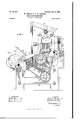
- Figure l is a broken side elevation, partly in section, of the improved wood-cutting machine embodying our invention.
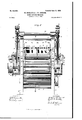
- Fig. 2 is a front elevation of the same.
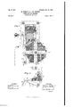
- Fig. 3 is a detail vertical section on the line III III of Fig. 2; and
- Fig. at is a detail sectional view of a modified arrangement of the bed or choppingblock, showing its relation to the cutter.
- the machine has a suitable frame 10,which can be of any necessaryshape, and, as illustrated, the opposite sides are connected by the usual stay-rods 11.
- Journaled transversely in the frame is a shaft 12, carrying the bed or chopping-block 13, which is preferably rotary, as illustrated in the main figures, but may be stationary, as shown in Fig. ,4 and hereinafter described.
- This bed or chopping-block 13 can be made in very many ways, the essential thing being that it have a series of faces on which the stick to be cut may lie and that it have longitudinal slots to receive the knives of the cutter, as presently described.
- the bed is formed with end spiders 14, having fourarms, each of which has a shoulder 14 to serve as a stop, as hereinafter described, and these spiders, which are secured to the shaft 12, are also bolted or otherwise fastened to end plates 15, which are slotted to receive the strips or blocks 16, which are fastened securely in place and the spaces between which receive the knives 17 of the cutter 18.
- the knives 17 of the cutter are, as shown, spaced apart by binding-blocks 19, which are vertically adjustable by means of the screws 20 in the cross-head 21, and the blocks and knives are held in place by bindingscrews 22 in the cross-head.
- binding-blocks 19 which are vertically adjustable by means of the screws 20 in the cross-head 21, and the blocks and knives are held in place by bindingscrews 22 in the cross-head.
- a slotted guide comprising the cross-bars 30 and the end plates 31, to which they are secured, this guide serving to stiffen the knives as they enter the stock below.
- the cross-head 21 slides in ways 23 in opposite sides of the frame 10, and to the main cross-head are bolted rearwardly-extending arms 24, which are attached to an auxiliary cross-head 25, which also slides vertically in ways 26 in the frame 10 and carries a knife 27, which as it reciprocates vertically is adapted to cut from a log or block 28 the slabs 29, which fall forward on the faces of the rotary bed or block 13 and are carried forward beneath the knives of the cutter 18.
- We have shown the arrangement for slabbing the log 28 simply to illustrate a means of getting slabs to the bed 13. As a matterof fact itis not likely that we should use this arrangement, and we do not limit our to any particular means of getting the slabs to the bed 13.
- the cross-head 21 can be moved vertically in any of several well-known ways; but we have illustrated a simple and strong, means of doing it. As shown, the cross-head connects at opposite ends by means of turn-- buckles 32 with levers 33, which move vertically on pivots 34, connecting them with the top of the frame 10, and by means of the tu r11- buckles it will be seen that the throw of the cross head may be adjusted-that is, its stroke regulated.
- the levers 33 are connected with the pitmen or connecting-rods 35, which extend downward and are pivoted to the bell-cranks 36 on opposite ends or sides of the machine, each bell-crank being fulcru med on a shaft 37 in the main frame, and the opposite'arm of the bell-crank carries a roller 38, engaging a grooved cam 39 on the driving-shaft 40.
- This shaft is provided with a driving-pulley 41, but of course can be turned in any usual way.
- Two of the arms have forwardly-extendin g threaded portions 46, on which are weights 47, adapted to tilt the shaft 44 and throw the arms 43 against the slab 29 with sufficient pressure to hold it in place, and it will be observed that when the cutter 18 descends the arms 43 will yield sufficiently to permit the necessary spreading of the stock or slab.
- weighted arms 46 can be of any necessary number or that springs can be substituted for the weights to throw the arms 43 against the stock.
- the bed 13 must be timed so that at the upstroke of the cutter 18 one of the sections of the bed shall he turned forward, so as to come beneath the cutter and bring the stock in place for the next downstroke thereof.
- This intermittent turning of the bed can be effected in any well-known way; but'the following means is well adapted for the purpose:
- the shaft 12, carrying the bed has at its ends gear-wheels 48, each of which meshes with a gear-wheel 49, j ournaled on the side of the frame 10, as shown at 50 in Fig. 1.
- a ratchet wheel 51 Connected with the gear-wheel is a ratchet wheel 51, which can be attached either directly to the gear-wheel 49 or secured to the shaft 50, and the ratchet-wheel is engaged and turned by a pawl 52, pivoted on the arm 53, which rocks on the shaft 50, said arm at its upper end being pivotally attached to the connecting-rod 54-, which, as shown at 55, is pivoted to a rock-arm 56, the latter rocking on the shaft 37, already referred to.
- On the shaft 55 is a roller 55, which is engaged by a cam 55 on the driving-shaft 40, the above arrangement being, as shown in Fig. 2, in d nplicate and at opposite sides of the machine.
- Some means has to be provided for holding the bed rigidly while the cutter 18 descends, and to this end dogs'57 are arranged on a cross-shaft 58, so that when the bed turns forward to bring a new slab or stock 29 into position the dogs will engage two of the shoulders 14 of the bed, and thus prevent
- the shaft 53 is provided with rearwardly-extending arms 59, which are provided with weights 60; but of course springs can be substituted for the weights, if desired.
- the shaft 58 has cranks (31, which are pivoted to pitmen G2, which extend forward and are pivoted to the shaft 55, already referred to.
- the cranks 61 are below the shaft 58, so that after the cam f5 has actuated the bed by means of the connected gearing already described a further movement of the cam will release the rollers 55 and permit the weights 60 to tilt the shaft 58 and throw back the arms 56 and also the dogs 57, this movement taking place during the upstroke of the cutter 18, when the cam 39 is advanced, so as to cause the said movement.
- the bed 13 When the bed 13 turns forward, it discharges the cut stock on a carrier 63, which is of the usual type and is at its lower end carried by a drum 64 on a shaft of the frame 10, the shaft having a driving-pulley 66, operated by abelt 67. Itis our intention to cut the stock sufficient] y long to be crosscut in several places to brin git into the length of commercial kindling-wood, and the carrier 63 is intended to convey the long strips to a suitable bundler; but of course any usual carrier can be used, and it can be arranged tov carry the wood Wherever desired.
- Figs. 3 and 4 it will be seen that several modifications might be illustrated, showing the relative arrangement of the cutter and stockthat is, showing them at relative angles, so that the knives will successively'strike the stock.
- the bed might be level and the knives of different height,thus making the inclination on the knives instead of the bed, or the bed can be stationary instead of movable, this arrangement being shown in Fig. 4, where the bed 68 has an inclined face 69, slotted to receive the knives 17, and having a recess 68 to receive a scraper or ejector 7 0, adapted to move over the inclined face of the bed and brush off the cut stock.
- this scraper is adapted to slide in the bell-cranks 72, one of which is shown; but of course two would be necessary, and the scraper or ejector is backed by springs 73 and adjustable up and down by screws 74.
- This arrangement is not claimed in detail; but any usual device to permit a yielding of the scraper can be employed.
- the bell-cranks are carried by a shaft 75, and one arm has a roller 76, engaging the groove 77 of the cam 78, so that as the cam revolves the bell-crank will be thrown forward and back, thus carrying the ejector or scraper combination of the reciprocating cutter havover the face of the bed and brushing off the stock.
- the continued movement of the driving-shaft causes the cutters to ascend, and the cam 55 engaging the rollers 55 actuates thelever mechanism referred to above and turns the ratchet-wheels 51 and gearwheels 49 and 48 and bed 13, so as to carry the slab 29 forward beneath the cutter 1S, and the dogs 57 engage two of the shoulders 14, so as to hold the bed 13 rigidly, while the pawls 43 engage the slab 29 to prevent its dis placement.
- the next descent of the cutters 18 and 27 causes the slab to be cut into several sticks, the number depending on the number of knives 17, and a new slab is cut from the log 28.
- On the next upstroke of the cutters the bed 13 is turned forward, as already described, the dogs 57 being released to permit it by means of the cranks 61 and pitmen 62 and the rock-arms 56. This operation'is continued indefinitely.
- a wood-cutting machine comprising a slotted bed, and a cutter having a series of knives to enter the stock, the surface of the bed and face of the cutter being relatively inclined so that the knives successively engage the stock, substantially as described.
- a wood-cutting machine comprising an inclined slotted bed, a cutter having knives in series to enter the bed-slots, and yielding arms hung opposite the lower edge of the bedface, substantially as described.
- a wood-cutting machine comprising a rotary bed having a plurality of slotted faces, a reciprocating cutter having knives to enter the slots of the bed, and means for locking the bed as a face of it registers with the out ter, substantially as described.
- a wood-cutting machine comprising a reciprocating cutter having a series of knives, a movable bed having slots to register with the knives, and a locking device to hold the bed in place beneath the knives, substantially as described.
- a rotary bed having a series of slotted sections to register with the cutter, means for successively moving the sections opposite the cutter, and a slabbing device to deliver slabs to the bed, substantially as described.
Landscapes
- Life Sciences & Earth Sciences (AREA)
- Engineering & Computer Science (AREA)
- Wood Science & Technology (AREA)
- Forests & Forestry (AREA)
- Debarking, Splitting, And Disintegration Of Timber (AREA)
Description
No. 65l,663. Patented June 12, {900.
- W. HINDL'EY '&. J.'-W. HARDING.
WOOD VGUTTING MACHINE.
(Application filed Feb. 4, 189B.)
3 Sheets-Sheet I.
(No Modal.)
WITNESSES:
//v VENTOBS: M A
H). BY
0 Q. J'tizzil m A TTORNE r.
HD.. WASHINGTON D c No. 65l,663. Patented lune 12, I900.
W. HINDLEY &. J. W. HARDING.
W000 CUTTING MACHINE.
I (Application filed Feb. 4, 1898.) (N0 lllode 3 Sheets-Sheet 2.
. Fly. 2.
W/TNESSES /N VE N T0195 1' 1mm...
M 2. $0, 6?. MW
A TTQRNE y.
1w: mums wzrzns co, PnoTaumo. WASHINGTON, u. c.
No. 65|,663. Patented lune I2, IQOIII W. HINDLEY & J. W. HARDING.
WOOD. CUTTING II'IAGI-IINE.
(Application flied Feb. 4, 1898.)
3 Sheets-Sheet 3.
(No Model.)
WITNESSES A TTOHNE I.
UNITED STATES ATENT OFFIcE.
WILLIAM HINDLEY, OF HOBOKEN, NEW JERSEY, AND JOSEPH IV. HARD- ING, OF NEW YORK, N. Y., ASSIGNORS, BY MESNE ASSIGNMENTS, TO
THE DIAMOND WOOD COMPANY,
OF NEW JERSEY.
WOOD-CUTTING MACHINE.
SPECIFICATION forming part of Letters Patent No. 651,663, dated June 12, 1900.
Application filed February 4, 1898. Serial No. 669,069. (No model.)
To all whom it may concern: Be it known that we, WILLIAM I-IINDLEY, of I-Ioboken,in the county of Hudson and State of New Jersey, and JOSEPH W. HARDING, of
The object of our invention is to produce a.
durable, simple, and substantial machine of this character which is adapted to use a reciprocating cutter having a series of knives whereby several sticks are cut at each stroke of the cutter; to arrange the cutter and the chopping-block or bed beneath it in such a way that the knives shall strike successively on the stock, thus enabling the latter to be cut with comparative ease to provide means for automatically delivering the stock to the knives; to arrange to automatically discharge the severed sticks and carry them away in such a manner that they will be held conveniently for bundling, and in general to produce a machine which can be easily operated,easily kept in repair, and conveniently adjusted.
To these ends our invention consists of certain features of construction and combinations of parts, which will be hereinafter fully described and claimed. v
Reference is to be had to the accompanying drawings, forming a part of this specification, in which similar figures of reference indicate corresponding parts in all the views.
Figure l is a broken side elevation, partly in section, of the improved wood-cutting machine embodying our invention. Fig. 2 is a front elevation of the same. Fig. 3 is a detail vertical section on the line III III of Fig. 2; and Fig. at is a detail sectional view of a modified arrangement of the bed or choppingblock, showing its relation to the cutter.
The machine has a suitable frame 10,which can be of any necessaryshape, and, as illustrated, the opposite sides are connected by the usual stay-rods 11. Journaled transversely in the frame is a shaft 12, carrying the bed or chopping-block 13, which is preferably rotary, as illustrated in the main figures, but may be stationary, as shown in Fig. ,4 and hereinafter described. This bed or chopping-block 13 can be made in very many ways, the essential thing being that it have a series of faces on which the stick to be cut may lie and that it have longitudinal slots to receive the knives of the cutter, as presently described. As illustrated, the bed is formed with end spiders 14, having fourarms, each of which has a shoulder 14 to serve as a stop, as hereinafter described, and these spiders, which are secured to the shaft 12, are also bolted or otherwise fastened to end plates 15, which are slotted to receive the strips or blocks 16, which are fastened securely in place and the spaces between which receive the knives 17 of the cutter 18. As shown, the rotary bed or block 13 has practically four independent beds adapted to suc= cessivel y register with the cutter 18, each section of the main bed having a face which when it comes to rest below the cutter 18, as shown clearly in Fig. 3, will be at an inclination to the lower edge of the cutter 18, so that when the latter descends the knives 17 thereof will successively engage the stock as they pass down through into the slots of the bed. This arrangement enables the cutter to work very smoothly and easily without excessive strain.
The knives 17 of the cutter are, as shown, spaced apart by binding-blocks 19, which are vertically adjustable by means of the screws 20 in the cross-head 21, and the blocks and knives are held in place by bindingscrews 22 in the cross-head. We have not attempted to describe in detail the. means of holding the blocks and knives, because it is evident that the knives can be fastened in any common way or may, indeed, be integral with the cross-head without in the least affecting the principle of the invention. Near the lower edges of the knives is a slotted guide comprising the cross-bars 30 and the end plates 31, to which they are secured, this guide serving to stiffen the knives as they enter the stock below.
The cross-head 21 slides in ways 23 in opposite sides of the frame 10, and to the main cross-head are bolted rearwardly-extending arms 24, which are attached to an auxiliary cross-head 25, which also slides vertically in ways 26 in the frame 10 and carries a knife 27, which as it reciprocates vertically is adapted to cut from a log or block 28 the slabs 29, which fall forward on the faces of the rotary bed or block 13 and are carried forward beneath the knives of the cutter 18. We have shown the arrangement for slabbing the log 28 simply to illustrate a means of getting slabs to the bed 13. As a matterof fact itis not likely that we should use this arrangement, and we do not limit ourselves to any particular means of getting the slabs to the bed 13. The cross-head 21 can be moved vertically in any of several well-known ways; but we have illustrated a simple and strong, means of doing it. As shown, the cross-head connects at opposite ends by means of turn-- buckles 32 with levers 33, which move vertically on pivots 34, connecting them with the top of the frame 10, and by means of the tu r11- buckles it will be seen that the throw of the cross head may be adjusted-that is, its stroke regulated. The levers 33 are connected with the pitmen or connecting-rods 35, which extend downward and are pivoted to the bell-cranks 36 on opposite ends or sides of the machine, each bell-crank being fulcru med on a shaft 37 in the main frame, and the opposite'arm of the bell-crank carries a roller 38, engaging a grooved cam 39 on the driving-shaft 40. This shaft is provided with a driving-pulley 41, but of course can be turned in any usual way.
When the slabs 29 fall forward on the faces of the bed 13, they are held against displacement as the bed turns forward by the pins 42, which serve as abutments for the back edges of the slabs, and when a slab is turned forward beneath the cutter 18 it is prevented from sliding off the bed by the weigh ted arms or pawls 43, which are hung in front of the bed and a little above it, the lower ends of the arms being curved rearwardly, so as to engage the slab, as shown clearly in Fig. 3. These arms are secured to a transverse shaft 44, and their rearward movement is limited by stop-pins 45 in the frame 10. Two of the armshave forwardly-extendin g threaded portions 46, on which are weights 47, adapted to tilt the shaft 44 and throw the arms 43 against the slab 29 with sufficient pressure to hold it in place, and it will be observed that when the cutter 18 descends the arms 43 will yield sufficiently to permit the necessary spreading of the stock or slab. It will of course be understood that these weighted arms 46 can be of any necessary number or that springs can be substituted for the weights to throw the arms 43 against the stock.
' any tilting of the latter.
Obviously the bed 13 must be timed so that at the upstroke of the cutter 18 one of the sections of the bed shall he turned forward, so as to come beneath the cutter and bring the stock in place for the next downstroke thereof. This intermittent turning of the bed can be effected in any well-known way; but'the following means is well adapted for the purpose: The shaft 12, carrying the bed, has at its ends gear-wheels 48, each of which meshes with a gear-wheel 49, j ournaled on the side of the frame 10, as shown at 50 in Fig. 1. Connected with the gear-wheel is a ratchet wheel 51, which can be attached either directly to the gear-wheel 49 or secured to the shaft 50, and the ratchet-wheel is engaged and turned by a pawl 52, pivoted on the arm 53, which rocks on the shaft 50, said arm at its upper end being pivotally attached to the connecting-rod 54-, which, as shown at 55, is pivoted to a rock-arm 56, the latter rocking on the shaft 37, already referred to. On the shaft 55 is a roller 55, which is engaged by a cam 55 on the driving-shaft 40, the above arrangement being, as shown in Fig. 2, in d nplicate and at opposite sides of the machine. It will be seen, therefore, that at each revolution of the driving-shaft the cams 55 will engage the rollers 55 and throw backward the arms 56 and connectingrods 54, thus tilting the arm 53 and causing the pawls 52 to engage the ratchet-wheels 51 and turn the gear- wheels 49 and 48 far enough to turn forward the bed 13 a distance of one section, thus bringing a new slab 29 beneath the cutter 1S and discharging the stock already out.
Some means has to be provided for holding the bed rigidly while the cutter 18 descends, and to this end dogs'57 are arranged on a cross-shaft 58, so that when the bed turns forward to bring a new slab or stock 29 into position the dogs will engage two of the shoulders 14 of the bed, and thus prevent In order that the dogs may swing automatically into position to engage the shoulders, the shaft 53 is provided with rearwardly-extending arms 59, which are provided with weights 60; but of course springs can be substituted for the weights, if desired. hen the cutter 18 descends, the bed 13 must turn forward again,
and means is provided to automatically release the dogs 57.
To this end the shaft 58 has cranks (31, which are pivoted to pitmen G2, which extend forward and are pivoted to the shaft 55, already referred to. The cranks 61 are below the shaft 58, so that after the cam f5 has actuated the bed by means of the connected gearing already described a further movement of the cam will release the rollers 55 and permit the weights 60 to tilt the shaft 58 and throw back the arms 56 and also the dogs 57, this movement taking place during the upstroke of the cutter 18, when the cam 39 is advanced, so as to cause the said movement.
When the bed 13 turns forward, it discharges the cut stock on a carrier 63, which is of the usual type and is at its lower end carried by a drum 64 on a shaft of the frame 10, the shaft having a driving-pulley 66, operated by abelt 67. Itis our intention to cut the stock sufficient] y long to be crosscut in several places to brin git into the length of commercial kindling-wood, and the carrier 63 is intended to convey the long strips to a suitable bundler; but of course any usual carrier can be used, and it can be arranged tov carry the wood Wherever desired.
With reference to Figs. 3 and 4 it will be seen that several modifications might be illustrated, showing the relative arrangement of the cutter and stockthat is, showing them at relative angles, so that the knives will successively'strike the stock. For instance, the bed might be level and the knives of different height,thus making the inclination on the knives instead of the bed, or the bed can be stationary instead of movable, this arrangement being shown in Fig. 4, where the bed 68 has an inclined face 69, slotted to receive the knives 17, and having a recess 68 to receive a scraper or ejector 7 0, adapted to move over the inclined face of the bed and brush off the cut stock. As shown,this scraper is adapted to slide in the bell-cranks 72, one of which is shown; but of course two would be necessary, and the scraper or ejector is backed by springs 73 and adjustable up and down by screws 74. This arrangement is not claimed in detail; but any usual device to permit a yielding of the scraper can be employed. The bell-cranks are carried by a shaft 75, and one arm has a roller 76, engaging the groove 77 of the cam 78, so that as the cam revolves the bell-crank will be thrown forward and back, thus carrying the ejector or scraper combination of the reciprocating cutter havover the face of the bed and brushing off the stock.
The operation of the machine will probably be clearly understood from the description already given; but in a general way it is as follows: Supposing a log or block 28 to be in position and the machine started, the cams 39, acting on the bell-cranks 36 and the connected lever mechanism, cause the descent of the cutters 1S and 27, the latter cutting off a slab 29 from the block or log 28, and the slab falls forward on the pins 42 and one face of the bed 13. The continued movement of the driving-shaft causes the cutters to ascend, and the cam 55 engaging the rollers 55 actuates thelever mechanism referred to above and turns the ratchet-wheels 51 and gearwheels 49 and 48 and bed 13, so as to carry the slab 29 forward beneath the cutter 1S, and the dogs 57 engage two of the shoulders 14, so as to hold the bed 13 rigidly, while the pawls 43 engage the slab 29 to prevent its dis placement. The next descent of the cutters 18 and 27 causes the slab to be cut into several sticks, the number depending on the number of knives 17, and a new slab is cut from the log 28. On the next upstroke of the cutters the bed 13 is turned forward, as already described, the dogs 57 being released to permit it by means of the cranks 61 and pitmen 62 and the rock-arms 56. This operation'is continued indefinitely.
Having thus described our invention, We claim as new and desire to secure by Letters Patent- 1. A wood-cutting machine, comprising a slotted bed, and a cutter having a series of knives to enter the stock, the surface of the bed and face of the cutter being relatively inclined so that the knives successively engage the stock, substantially as described.
2. A wood-cutting machine, comprising an inclined slotted bed, a cutter having knives in series to enter the bed-slots, and yielding arms hung opposite the lower edge of the bedface, substantially as described.
3. A wood-cutting machine, comprising a rotary bed having a plurality of slotted faces, a reciprocating cutter having knives to enter the slots of the bed, and means for locking the bed as a face of it registers with the out ter, substantially as described.
4. A wood-cutting machine, comprising a reciprocating cutter having a series of knives, a movable bed having slots to register with the knives, and a locking device to hold the bed in place beneath the knives, substantially as described.
5. In a machine of the kind described, the combination of the reciprocating cutter having a series of knives, a movable bed having slots to receive the knives, and a second cutter arranged to slab-stock and deliver the slabs to the bed and knives, substantially as described.
6. In a machine of the kind described, the
ing a series of knives, a rotary bed having a series of slotted sections to register with the cutter, means for successively moving the sections opposite the cutter, and a slabbing device to deliver slabs to the bed, substantially as described.
7. The combination with the bed having a plurality of inclined faces, and the reciprocating cutter opposite the bed, of the yield-- ing arms opposite the bed arranged to come opposite the lower edge of each face as the bed comes to rest, substantially as described. 8. The combination with the bed rotating on a horizontal axis and provided with a series of faces, of shoulders for each face at the ends of the bed, dogs automatically pressed to engagement with the shoulders, and a lever mechanism to automatically release the dogs, substantially as described.
WILLIAM HINDLEY. JOSEPH W. HARDING. Witnesses:
W.B. HUTOHINSON, BERTHA DEYO.
Priority Applications (1)
| Application Number | Priority Date | Filing Date | Title |
|---|---|---|---|
| US66906998A US651663A (en) | 1898-02-04 | 1898-02-04 | Wood-cutting machine. |
Applications Claiming Priority (1)
| Application Number | Priority Date | Filing Date | Title |
|---|---|---|---|
| US66906998A US651663A (en) | 1898-02-04 | 1898-02-04 | Wood-cutting machine. |
Publications (1)
| Publication Number | Publication Date |
|---|---|
| US651663A true US651663A (en) | 1900-06-12 |
Family
ID=2720232
Family Applications (1)
| Application Number | Title | Priority Date | Filing Date |
|---|---|---|---|
| US66906998A Expired - Lifetime US651663A (en) | 1898-02-04 | 1898-02-04 | Wood-cutting machine. |
Country Status (1)
| Country | Link |
|---|---|
| US (1) | US651663A (en) |
Cited By (1)
| Publication number | Priority date | Publication date | Assignee | Title |
|---|---|---|---|---|
| US4388957A (en) * | 1974-08-30 | 1983-06-21 | Macmillan Bloedel Limited | Multiple blade splitting device |
-
1898
- 1898-02-04 US US66906998A patent/US651663A/en not_active Expired - Lifetime
Cited By (1)
| Publication number | Priority date | Publication date | Assignee | Title |
|---|---|---|---|---|
| US4388957A (en) * | 1974-08-30 | 1983-06-21 | Macmillan Bloedel Limited | Multiple blade splitting device |
Similar Documents
| Publication | Publication Date | Title |
|---|---|---|
| US651663A (en) | Wood-cutting machine. | |
| US406455A (en) | Automatic hay-press | |
| US219296A (en) | Improvement in machines for slicing logs into strips | |
| US447846A (en) | Excelsior-cutting machine | |
| US1059376A (en) | Combination lath and shingle machine. | |
| US328399A (en) | Nail-plate-feeding machine | |
| US1012539A (en) | Set-works for sawmills. | |
| US157594A (en) | Improvement in apparatus for making cube-sugar | |
| US400999A (en) | Meat-chopping machine | |
| US390207A (en) | Hoop-machine | |
| US6134A (en) | of boston | |
| US697497A (en) | Sawing-machine. | |
| US390601A (en) | Feed-cutter | |
| US673243A (en) | Machine for making matches. | |
| US675877A (en) | Bank-bill cutter. | |
| US376251A (en) | mcintyre | |
| US766295A (en) | Shingle-mill. | |
| US304826A (en) | jokes | |
| US178676A (en) | Improvement in straw-cutters | |
| USRE4263E (en) | Improvement in machines for cutting stone | |
| US17061A (en) | Liams | |
| US6950A (en) | Operating the hammers of spike-machines | |
| US26823A (en) | Method of hanging reciprocating saws | |
| US607602A (en) | The norris peters co | |
| US203509A (en) | Improvement in machines for goring veneers for barrels |