US6512676B1 - Printed circuit board stiffener - Google Patents
Printed circuit board stiffener Download PDFInfo
- Publication number
- US6512676B1 US6512676B1 US09/619,725 US61972500A US6512676B1 US 6512676 B1 US6512676 B1 US 6512676B1 US 61972500 A US61972500 A US 61972500A US 6512676 B1 US6512676 B1 US 6512676B1
- Authority
- US
- United States
- Prior art keywords
- printed circuit
- circuit board
- stiffener
- mounting frame
- elongated
- Prior art date
- Legal status (The legal status is an assumption and is not a legal conclusion. Google has not performed a legal analysis and makes no representation as to the accuracy of the status listed.)
- Expired - Fee Related
Links
Images


Classifications
-
- H—ELECTRICITY
- H05—ELECTRIC TECHNIQUES NOT OTHERWISE PROVIDED FOR
- H05K—PRINTED CIRCUITS; CASINGS OR CONSTRUCTIONAL DETAILS OF ELECTRIC APPARATUS; MANUFACTURE OF ASSEMBLAGES OF ELECTRICAL COMPONENTS
- H05K7/00—Constructional details common to different types of electric apparatus
- H05K7/14—Mounting supporting structure in casing or on frame or rack
- H05K7/1461—Slidable card holders; Card stiffeners; Control or display means therefor
-
- H—ELECTRICITY
- H05—ELECTRIC TECHNIQUES NOT OTHERWISE PROVIDED FOR
- H05K—PRINTED CIRCUITS; CASINGS OR CONSTRUCTIONAL DETAILS OF ELECTRIC APPARATUS; MANUFACTURE OF ASSEMBLAGES OF ELECTRICAL COMPONENTS
- H05K1/00—Printed circuits
- H05K1/02—Details
- H05K1/0271—Arrangements for reducing stress or warp in rigid printed circuit boards, e.g. caused by loads, vibrations or differences in thermal expansion
Definitions
- the present invention relates generally to the field of printed wiring boards and, more particularly, to mechanical stiffener apparatus and methods for rigidifying printed circuit boards.
- Modern high performance computers contain a number of printed circuit boards (PCB) to carry and interconnect the various integrated circuit chips and other components that make up the computer system.
- Computers may be configured to have one or more subsystems, each in its own right a computer, that are interconnected into a larger, greater capacity computer.
- Each subsystem may contain basically the same components assembled in a chassis.
- Within a given subsystem there may be, among others, a processor board, a power board, and any number of secondary or daughter boards that are carried upon a support structure within the subsystem chassis. These subsystems of boards are carried in racks in the computer chassis.
- processors are so named as they have attached to them one or more processors, or central processing units (CPU).
- the CPU is an integrated circuit (IC) chip that is considered the “brains” of the computer.
- the processor board serves as a communication medium for the exchange of electrical signals among the one or more attached processors and other electrical components attached to the processor boards, daughter cards, and other components.
- the processor board itself is sometimes referred to as a backplane, mother board, system board, or mainboard, depending on its function and configuration.
- the processor board is a printed circuit board.
- a PCB is a relatively thin, flat sheet structure.
- the PCB may be made of laminations of reinforced fiberglass or plastic and metallic interconnects which electrically link the components attached to the board.
- As flat sheets, PCBs are subject to bending and flexing stresses depending on the weight of the attached components and the method used to attach the PCB to the chassis.
- processors are an assembly consisting of a processor module and a power conditioning module with attached heatsink. These assemblies are relatively large and heavy, wherein the structural integrity of the PCB comes into question.
- the localized weight of the processor assembly combined with the combined weight of the other components assembled onto the processor board, requires that the PCB be able to support handling, assembly and other stresses within acceptable limits of flexure without compromising the structural integrity of the PCB. Excessive loading will have a detrimental effect on the integrity of the electrical component interconnects and may result in failure of the electrical system.
- a processor board is commonly supported to some degree by the mounting bolts used for mounting the processor board to the chassis.
- Supplemental support is sometimes provided by rigidity enhancers laterally or longitudinally disposed across the processor board. These rigidity enhancers have taken various forms.
- lateral and longitudinal rigidity enhancers include electrical component interference, cooling air flow blockage and deflection, and lack of strength to support a PCB with attached processor assemblies. Improved lateral and longitudinal rigidity enhancers are needed that minimize electrical component interference, minimize the blockage of cooling air flow, and have sufficient strength to support a fully loaded PCB.
- the large processor assemblies take up considerable surface area of the board.
- components which are commonly attached to the PCB are moved to other locations on the board or moved entirely off the board onto daughter boards.
- the distances between electrical components become large which is detrimental to the performance of the system as a whole.
- Processor assembly mounting structures have been used in the art to support the processor module and power conditioner module as an assembly. These structures have taken the form of a frame that supports the outside edge of the processor assembly. The processor module and power conditioner module are electrically connected, and the assembly is mounted onto the frame. Fasteners are used between the frame and the PCB to mount the processor assembly to the PCB. The frames elevate the processor assembly from the surface of the PCB allowing the attachment of additional electrical components onto the PCB surface that would have been covered by the processor assembly if directly attached.
- the state of the art processor assembly mounting frame requires considerable PCB surface area, limiting the number of electrical components capable of being attached to the PCB.
- the present invention is directed to apparatus and methods for enhancing processor board rigidity by providing processor board stiffeners and processor assembly mounting frames adapted to mount on a processor board surface.
- the stiffeners and mounting frames resist deflection of the processor board due to the weight of the processor assembly and other components.
- the mounting frame additionally, provides accommodation for additional electrical components to be attached to the PCB by elevating the processor assembly off of the PCB, thus providing additional PCB surface area for the attachment of components.
- the mounting frame is a frame-like structure having external dimensions configured to support an attached electrical component or components.
- the mounting frame comprises a plurality of legs, a cross leg, a rectangular opening, a partial rectangular opening, a plurality of through-holes, and a plurality of pilot holes.
- the plurality of legs includes an inwardly extending lip. The inwardly extending lip provides additional support material for supporting the attached components while minimizing the PCB surface area covered by the frame.
- the mounting frame is relatively thin but rigid. The legs of the mounting frame, in combination with the cross leg, define a rectangular opening and a partial rectangular opening.
- the partial rectangular opening is adapted to accommodate a component attached to the circuit board.
- a plurality of pilot holes is provided which are adapted to accommodate mounting means for attachment of the mounting frame to a printed circuit board (PCB).
- a plurality of through-holes is provided and adapted to accommodate mounting means for attachment of one or more electrical components to the mounting frame.
- the mounting frame is adapted such that the mounting frame peripheral edge substantially conforms to the outer dimensions of the electrical component.
- the mounting frame peripheral edge overlaps the electrical component bottom surface, such that when the mounting frame is placed against the electrical component bottom surface, the mounting frame rests upon the outer portion of the bottom surface.
- the fastening means is adapted to make use of the through-holes to fasten the mounting frame to the electrical component.
- the peripheral edge of the electrical component overlaps the perimeter of the mounting frame. In an alternative embodiment, the peripheral edge of the mounting frame overlaps the perimeter of electrical component.
- One embodiment in accordance with the present invention includes a truss-like stiffener having external dimensions adapted to support an attached printed circuit board having attached components.
- the stiffener is relatively thin but rigid.
- the stiffener comprises a plurality of legs which define a plurality of openings.
- the stiffener has a fastening surface which is adapted to accommodate a fastening means for fastening to a PCB.
- the openings are provided such as to not significantly impede the flow of cooling fluid.
- the legs may be formed as an integral unit from a solid sheet of flat stock material.
- the legs may be formed by, among other methods, machining, cutting, and extruding.
- the legs are formed as separate units of stock material and subsequently fastened into the truss-like configuration.
- the legs may be fastened together by, among other methods, welding, brazing, gluing, and screwing.
- the stiffener is made from a material that is thermally conductive. In this embodiment, the stiffener may be used as part of a heat dissipation system. In another embodiment, the stiffener is made from a material that is electrically conductive. In this embodiment, the stiffener may be used as part of a power or grounding system. In another embodiment, the stiffener is made from an electrically insulative material to minimize electrical shorting.
- stiffeners and mounting frames are used in combination to rigidify the PCB.
- Two stiffeners are positioned on one side of the PCB, in this example, while the opposite side of the PCB has attached one or more mounting frames.
- the two stiffeners are positioned perpendicular to the long dimension of the mounting frames.
- the stiffeners span substantially the width of the PCB.
- the present invention reduces the deflection to an acceptable amount in an efficient and economic manner which does not interfere with other electrical components or cooling flow requirements.
- FIG. 1 illustrates a mounting frame, in accordance with one embodiment of the present invention.
- FIG. 2 illustrates a cross sectional view of the mounting frame of FIG. 1, in accordance with one embodiment of the present invention.
- FIG. 3 illustrates a cross sectional view of the mounting frame of FIG. 1, in accordance with one embodiment of the present invention.
- FIG. 4 illustrates a cross sectional view of the mounting frame of FIG. 1, in accordance with one embodiment of the present invention.
- FIG. 5 illustrates the mounting frame of FIG. 1 as assembled to a processor assembly, in accordance with one embodiment of the present invention.
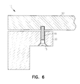
- FIG. 6 illustrates a cross sectional view of the mounting frame of FIG. 1 as assembled to a processor assembly, in accordance with one embodiment of the present invention.
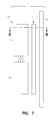
- FIG. 7 illustrates a side exploded view of an embodiment of the mounting frame of FIG. 1 with a processor assembly and a printed circuit board, in accordance with one embodiment of the present invention.
- FIG. 8 illustrates a cross sectional view of the mounting frame of FIG. 1 as assembled to a processor assembly and a printed circuit board, in accordance with one embodiment of the present invention.
- FIG. 9 illustrates a printed circuit board stiffener, in accordance with one embodiment of the present invention.
- FIG. 10 illustrates a side exploded view of the mounting frame of FIG. 1, a plurality of board stiffeners, a processor assembly and a printed circuit board, in accordance with one embodiment of the present invention.
- FIG. 11 illustrates a top view of a printed circuit board with attached stiffeners, in accordance with one embodiment of the present invention.
- FIG. 12 illustrates a bottom view of a printed circuit board with attached mounting frames, in accordance with one embodiment of the present invention.
- FIG. 1 depicts mounting frame 10 , in accordance with an embodiment of the present invention.
- Mounting frame 10 is a frame-like structure having external dimensions adapted to support an attached electrical component or components, which will be described subsequently.
- Mounting frame 10 comprises a plurality of legs 12 , cross leg 13 rectangular opening 16 , partial rectangular opening 14 , a plurality of through-holes 19 , and a plurality of pilot holes 18 .
- Mounting frame 10 is relatively thin but rigid.
- Legs 12 of mounting frame 10 in combination with cross leg 13 , define a rectangular opening 16 and a partial rectangular opening 14 .
- a plurality of pilot holes 18 are provided. Pilot holes 18 are adapted to accommodate mounting means for attachment of mounting frame 10 to a printed circuit board (PCB).
- a plurality of through-holes 19 are provided and adapted to accommodate a mounting means for attachment of one or more components to mounting frame 10 .
- legs 12 and cross leg 13 are formed as an integral unit from a solid sheet of flat stock material. In another embodiment, legs 12 and cross leg 13 are formed by, among other methods, machining, cutting, and extruding. Legs 12 and cross leg 13 also may be formed as separate units of flat stock material and subsequently fastened into the configuration as illustrated in FIG. 1 . Legs 12 and cross leg 13 may be fastened together by, among other methods, welding, brazing, gluing, and screwing.
- mounting frame 10 can take many forms depending on the configuration of the one or more attached components.
- partial rectangular opening 14 is provided to accommodate an electrical component on the PCB.
- partial rectangular opening 14 would not be necessary and other configurations may be used, among others, such as two complete rectangles or one rectangle. It is understood that the configuration of legs 12 and cross leg 13 can take many forms without departing from the scope of the invention.
- pilot holes 18 and through-holes 19 are provided to aid in fastening the mounting frame to components and to the PCB. Pilot holes 18 and through-holes 19 are provided for the fastening means and maybe not provided or take other forms for different fastening means.
- An example of fastening means not requiring pilot holes 18 and through-holes 19 include, among others, clips, adhesive, and brazing.
- an electrical component is attached to mounting frame 10 by a fastening means.
- the electrical component is a processor assembly consisting of a processor module and a power conditioner.
- the processor module and power conditioner are assembled and are in electrical communication via a male/female connector.
- the processor assembly is mounted onto mounting frame 10 by a fastening means.
- the assembled processor assembly and mounting frame 10 are then mounted to the PCB with a fastening means.
- Mounting frame 10 may be fabricated from any material, such as rigid plastic or metal. In some embodiments, it may be desirable to make mounting frame 10 electrically conductive. In other embodiment, it may be desirable to make mounting frame 10 electrically insulative. The choice of material for mounting frame 10 will be determined by the application of the invention.
- FIG. 2 presents a cross-sectional view of mounting frame 10 on section line 2 — 2 shown in FIG. 1, in accordance with one embodiment of the present invention.
- Mounting frame 10 includes an inwardly extending lip 20 .
- Inwardly extending lip 20 provides additional support material for supporting the attached electrical components while minimizing the surface contact area between mounting frame 10 and the PCB, as will be discussed subsequently.
- Leg 10 includes top surface 12 , intermediate surface 21 and bottom surface 11 . The distance between intermediate surface 21 and bottom surface 11 is adapted to provide clearance for attached components under inwardly extending lip 20 and an attached component.
- mounting frame 10 to include inwardly extending lip 20 will be determined by the material from which mounting frame 10 is fabricated. For some materials, such as, among others, metal and plastic, the inwardly extending lip 20 may be machined from a blank of material. In other materials, such as, among others, plastic and fiberglass, it can be produced as part of a molding or lay-up process. Inwardly extending lip 20 may also be a component which must be assembled to resemble the illustration of FIG. 2, without departing from the scope of the invention.
- FIG. 3 presents a view of mounting frame 10 on section line 3 — 3 shown in FIG. 1, in accordance with one embodiment of the present invention. Visible in the illustration is a cross section of mounting frame 10 , including inwardly extending lip 20 , further including pilot hole 18 . Pilot hole 18 is provided to accommodate a fastening means for fastening mounting frame 10 to a printed circuit board. Such fastening means may include, among others, fasteners such as screws and bolts. Pilot hole 18 may be threaded to accommodate threaded fasteners.
- FIG. 4 presents a view of mounting frame 10 on section line 4 — 4 shown in FIG. 1, in accordance with one embodiment of the present invention. Visible in the illustration is a cross section of mounting frame 10 , including inwardly extending lip 20 , further including through-hole 19 . Through-hole 19 is provided in inwardly extending lip 20 to accommodate an attachment means for attaching mounting frame 10 to a component.
- attachment means may include, among others, fasteners such as screws and bolts.
- the fastening means applied to fasten mounting frame 10 to components or PCBs will determine how mounting frame 10 will be adapted to accommodate such fastening means.
- the fastening means may not require that mounting frame 10 have pilot holes 18 as shown in FIG. 2, and similarly, through-holes 19 as shown in FIG. 4 .
- the fastening means may consist of, among others, bonding, brazing, and clipping.
- FIG. 5 depicts a bottom view of mounting frame 10 of the embodiment of FIG. 1 as coupled to electrical component assembly 52 , in accordance with one embodiment of the present invention.
- Mounting frame 10 is removably coupled component assembly 52 .
- component assembly 52 consists of a first component 53 and a second component 54 .
- first component 53 is a processor module and second component 54 is a power conditioner for the processor module.
- the first component 53 and the second component 54 are in electrical communication through a male/female close-fit coupling 55 .
- mounting frame 10 is adapted such that the amounting frame peripheral edge substantially conforms to the outer dimensions of the electrical component assembly 52 , such that leg top surface 12 abuts the bottom surface of electrical component assembly 52 .
- leg top surface 12 rests upon the outer portion of the bottom surface of electrical component assembly 52 .
- the fastening means is adapted to make use of through-holes 19 to fasten mounting frame 10 to electrical component assembly 52 .
- the peripheral edge of electrical component assembly 52 overlaps the perimeter of mounting frame 10 . In another embodiment, the peripheral edge of mounting frame 10 overlaps the perimeter of electrical component assembly 52 .
- the exact orientation of the electrical component assembly 52 in relationship to mounting frame 10 will depend on the size and weight of electrical component assembly 52 . Similarly, the dimensions of legs 12 will depend on the size and weight of the attached electrical components.
- FIG. 6 depicts a view of mounting frame 10 and electrical component assembly 52 on section line 6 — 6 shown in FIG. 5, in accordance with an embodiment of the present invention.
- a cross section of mounting frame 10 including inwardly extending lip 20 and through-hole 19 , and a cross-section of electrical component assembly 52 is shown.
- Through-hole 19 is provided in inwardly extending lip 20 to accommodate an attachment means 15 for fastening mounting frame 10 to electrical component assembly 52 .
- attachment means 15 may include, among others, fasteners such as screws and bolts.
- FIG. 7 depicts a side elevation exploded view of mounting frame 10 of the embodiment of FIG. 1, electrical component assembly 52 , and PCB 50 .
- Mounting frame 10 is disposed between electrical component assembly 52 and PCB 50 as would be configured when assembled.
- mounting frame 10 is coupled to electrical component assembly 52 , and then mounting frame 10 is coupled to PCB 50 .
- mounting frame 10 is coupled to PCB 10 first, and then to electrical component assembly 52 .
- FIG. 8 depicts a cross sectional view of mounting frame 10 , electrical component assembly 52 , and PCB 50 on section line 8 — 8 of the embodiment of FIG. 7.
- a cross-sectional view of mounting frame 10 including inwardly extending lip 20 and pilot hole 18 , a cross-sectional view of electrical component assembly 52 , and a cross-sectional view of PCB 50 is shown.
- Pilot hole 18 is provided in mounting frame 10 to accommodate attachment means 17 for fastening mounting frame 10 to PCB 50 .
- attachment means may include, among others, fasteners such as screws and bolts.
- through-holes 19 and pilot holes 18 are not provided in mounting frame 10 .
- Fastening means for this configuration include, among others, bonding, brazing, welding, and gluing.
- the portion of PCB 50 under inwardly facing lip 20 may be populated with electrical components.
- FIG. 9 depicts stiffener 60 in accordance with one embodiment of the present invention.
- Stiffener 60 is a truss-like structure having dimensions adapted to support an attached printed circuit board.
- Stiffener 60 is relatively thin but rigid.
- Legs 62 define a plurality of triangular openings 66 .
- Stiffener 60 has a fastening surface 68 which is adapted to accommodate a fastening means for fastening to a PCB.
- Triangular openings 66 are adapted such as to not significantly impede the flow of cooling fluid, as will be subsequently discussed.
- Stiffener 60 may be formed as an integral unit from a solid sheet of flat stock material with cut-outs defining legs 62 .
- Legs 62 may be formed by, among other methods, machining, cutting, and extruding.
- Legs 62 also may be formed as separate units of stock material and subsequently fastened into the configuration as illustrated in FIG. 9 .
- Legs 62 may be fastened together by, among other methods, welding, brazing, gluing, and screwing.
- Stiffener 60 may be die-cast, routed or otherwise manufactured.
- Stiffener 60 may be formed of sheet metal, cast metal, plastic, graphite, fiberglass, or any material well suited for stiffening the processor board.
- stiffener 60 as well as the configuration of legs 62 with respect to one another, is dependent on the distribution and weight of the components contained on the PCB.
- a partial triangular opening is provided to accommodate and span over an electrical component on the PCB.
- legs 62 are arranged to form diamond-shaped openings. These are just examples and other arrangements of legs 62 are possible without deviating from the scope of the invention.
- Stiffener 60 may be fabricated from any material, such as, among others, rigid plastic or metal. In some embodiments, it may be desirable to make the stiffener thermally or electrically conductive. In other embodiments, it may be desirable to make stiffener 60 electrically insulative. The choice of material for stiffener 60 will be determined by the application if the invention.
- stiffener 60 could be altered to accommodate differing requirements.
- the height and length of stiffener 60 is adapted to accommodate the size of the board and the space of the chassis.
- the configuration of legs 62 may define rectangular or trapezoid apertures, among others, to accommodate differing strength requirements. It is also to be understood that the thickness of stiffener 60 could vary as well.
- Stiffener 60 is mounted firmly to the processor board in such a way that stiffener 60 supports the PCB against deflection and warping. In one embodiment, stiffener 60 is mounted perpendicular to the surface of the PCB. In one embodiment, stiffener 60 is mounted perpendicular to and substantially parallel to one of the edges of the PCB. In another embodiment, a plurality of stiffeners 60 are used in parallel relationship to each other spanning the PCB.
- stiffeners 60 may be used on any type of PCB that requires board stiffeners to support attached components.
- FIG. 10 depicts a side elevation exploded view of mounting frame 10 and stiffeners 60 , electrical component assembly 52 , and PCB 50 , in accordance with an embodiment of the present invention.
- Two stiffeners 60 are positioned on PCB 50 on the opposite side of PCB 50 from mounting frame 10 , and perpendicular to the long dimension of mounting frame 10 .
- Stiffeners 60 are positioned perpendicular to the width of mounting frame 10 adding additional support under electrical component assembly 52 .
- Stiffeners 60 span substantially the width of PCB 50 .
- Stiffener 60 may be mounted on the bottom side or the top side of the PCB according to the requirements of the configuration. Stiffeners 60 may be mounted in any of a variety of methods including bolts, epoxy, and cement.
- one or more stiffeners 60 are adapted to be mounted on the component side of a PCB 50 .
- one or more stiffeners 60 are mounted to the back side of PCB 50 .
- Stiffener 60 is adapted for avoiding interference with metal runs, solder joints, as well as components.
- stiffener 60 can have missing legs 62 or gaps, allowing stiffener 60 to span above the subject components.
- the mounted stiffeners 60 are adapted to a height such that they do not interfere with chassis assembly, generally no higher than the height of the tallest component attached to PCB 50 but are of sufficient height to provide the required support to PCB 50 .
- stiffener 60 provides lateral rigidity while the mounting frame provides longitudinal rigidity.
- FIGS. 11 and 12 are provided to illustrate the method of use of the present invention as applied to an advanced processor board configuration.
- electronic components are attached to both sides of processor board 1 15 .
- processor board 115 is a modified McKinley (Intel Corporation, Santa Clara, Calif.) protocol processor board.
- Two HUB chip sets 125 and other attached components are on processor board top side 117 .
- Two stiffeners 60 are disposed in the longitudinal direction of board 115 , with HUB chip sets 125 disposed between the two stiffeners 60 .
- Stiffeners 60 are positioned perpendicular to processor assembly mounting frame 10 , shown in FIG. 10, and are located opposite to processor module 54 of processor assembly 52 .
- FIG. 12 illustrates four processor assemblies 152 and their corresponding mounting frames 110 coupled to processor board back side 113 .
- the heavy weight and size of the McKinley processor assembly 153 presents a unique structural challenge for processor board 115 .
- the weight of the McKinley processor assembly 153 can cause deflection in an unsupported processor board 115 .
- the present invention reduces the deflection to an acceptable amount, in an efficient and economic manner which does not interfere with other electrical components or cooling flow requirements.
Landscapes
- Engineering & Computer Science (AREA)
- Microelectronics & Electronic Packaging (AREA)
- Mounting Of Printed Circuit Boards And The Like (AREA)
Abstract
Description
Claims (10)
Priority Applications (2)
| Application Number | Priority Date | Filing Date | Title |
|---|---|---|---|
| US09/619,725 US6512676B1 (en) | 2000-07-20 | 2000-07-20 | Printed circuit board stiffener |
| US10/202,377 US6771517B2 (en) | 2000-07-20 | 2002-07-26 | Printed circuit board stiffener |
Applications Claiming Priority (1)
| Application Number | Priority Date | Filing Date | Title |
|---|---|---|---|
| US09/619,725 US6512676B1 (en) | 2000-07-20 | 2000-07-20 | Printed circuit board stiffener |
Related Child Applications (1)
| Application Number | Title | Priority Date | Filing Date |
|---|---|---|---|
| US10/202,377 Division US6771517B2 (en) | 2000-07-20 | 2002-07-26 | Printed circuit board stiffener |
Publications (1)
| Publication Number | Publication Date |
|---|---|
| US6512676B1 true US6512676B1 (en) | 2003-01-28 |
Family
ID=24483032
Family Applications (2)
| Application Number | Title | Priority Date | Filing Date |
|---|---|---|---|
| US09/619,725 Expired - Fee Related US6512676B1 (en) | 2000-07-20 | 2000-07-20 | Printed circuit board stiffener |
| US10/202,377 Expired - Lifetime US6771517B2 (en) | 2000-07-20 | 2002-07-26 | Printed circuit board stiffener |
Family Applications After (1)
| Application Number | Title | Priority Date | Filing Date |
|---|---|---|---|
| US10/202,377 Expired - Lifetime US6771517B2 (en) | 2000-07-20 | 2002-07-26 | Printed circuit board stiffener |
Country Status (1)
| Country | Link |
|---|---|
| US (2) | US6512676B1 (en) |
Cited By (11)
| Publication number | Priority date | Publication date | Assignee | Title |
|---|---|---|---|---|
| US6697130B2 (en) * | 2001-01-16 | 2004-02-24 | Visteon Global Technologies, Inc. | Flexible led backlighting circuit |
| US6771517B2 (en) * | 2000-07-20 | 2004-08-03 | Silicon Graphics, Inc. | Printed circuit board stiffener |
| US20040253842A1 (en) * | 2003-06-11 | 2004-12-16 | Hewlett-Packard Development Company, L.P. | Backplane support system |
| US20070134945A1 (en) * | 2005-12-13 | 2007-06-14 | Nitto Denko Corporation | Plate-reinforced wiring circuit board |
| US7289337B2 (en) * | 2002-12-13 | 2007-10-30 | Thales | Electronic card with braced structure |
| US20080000675A1 (en) * | 2006-06-30 | 2008-01-03 | Honeywell International Inc. | System and method of providing structural support to printed wiring assembly components |
| US20080123306A1 (en) * | 2006-11-23 | 2008-05-29 | Ted Ju | Circuit board back plate |
| WO2008155498A2 (en) * | 2007-06-21 | 2008-12-24 | Airbus France | Avionics equipment |
| US20100096743A1 (en) * | 2008-09-29 | 2010-04-22 | Sanka Ganesan | Input/output package architectures, and methods of using same |
| US11096298B2 (en) * | 2019-04-22 | 2021-08-17 | Krambu Inc. | Power distribution bus bar for distributing power to surface mount connectors |
| US20230200023A1 (en) * | 2021-12-16 | 2023-06-22 | International Business Machines Corporation | Temporary structural bulkhead in an electronic enclosure |
Families Citing this family (7)
| Publication number | Priority date | Publication date | Assignee | Title |
|---|---|---|---|---|
| US6943292B2 (en) * | 2003-05-12 | 2005-09-13 | Siemens Vdo Automotive Corporation | Printed circuit board stiffener |
| KR100659066B1 (en) * | 2004-10-13 | 2006-12-19 | 삼성에스디아이 주식회사 | Modular Print Board Assembly And Plasma Display Device Therewith |
| US7381908B1 (en) | 2005-07-07 | 2008-06-03 | Cosimo Cantatore | Circuit board stiffener |
| US7459782B1 (en) * | 2005-10-05 | 2008-12-02 | Altera Corporation | Stiffener for flip chip BGA package |
| US7869220B2 (en) * | 2008-07-25 | 2011-01-11 | Honeywell International Inc. | Stiffening support for printed circuit assemblies |
| US8766099B2 (en) * | 2009-09-29 | 2014-07-01 | Apple Inc. | Component mounting structures for electronic devices |
| FR3037768B1 (en) * | 2015-06-17 | 2018-06-15 | Alstom Transport Technologies | ELECTRONIC CARD WITH MONOBLOC STIFFENER |
Citations (12)
| Publication number | Priority date | Publication date | Assignee | Title |
|---|---|---|---|---|
| US4807407A (en) * | 1987-06-22 | 1989-02-28 | Pbs Building Systems | Modular building system for a three-story structure |
| US4988577A (en) | 1989-06-08 | 1991-01-29 | Bussco Engineering, Inc. | Printed circuit board stiffener |
| US5186377A (en) * | 1991-04-29 | 1993-02-16 | Intergraph Corporation | Apparatus for stiffening a circuit board |
| US5198279A (en) | 1991-02-28 | 1993-03-30 | Amp Incorporated | Circuit board stiffener |
| US5378545A (en) | 1993-04-02 | 1995-01-03 | Ag Communication Systems Corporation | Removable snap-on card stiffener |
| US5453580A (en) * | 1993-11-23 | 1995-09-26 | E-Systems, Inc. | Vibration sensitive isolation for printed circuit boards |
| US5557503A (en) | 1995-05-12 | 1996-09-17 | International Business Machines Corporation | Circuit card having a large module strain relief and heat sink support |
| US5893466A (en) * | 1997-06-27 | 1999-04-13 | Sun Microsystems, Inc. | Support for printed circuit board during processing |
| US5900850A (en) * | 1996-08-28 | 1999-05-04 | Bailey; James Tam | Portable large scale image display system |
| US5934485A (en) * | 1997-12-24 | 1999-08-10 | Northern Telecom Limited | Telecommunications rack |
| US6084182A (en) | 1997-04-07 | 2000-07-04 | Hybricon Corporation | Backplane stiffener |
| US6260265B1 (en) * | 1998-04-27 | 2001-07-17 | Power Distribution Products | Circuit board stiffener |
Family Cites Families (4)
| Publication number | Priority date | Publication date | Assignee | Title |
|---|---|---|---|---|
| US4533978A (en) * | 1983-06-06 | 1985-08-06 | Bucklee-Mears Company | Circuit board stiffening |
| US5107404A (en) * | 1989-09-14 | 1992-04-21 | Astec International Ltd. | Circuit board assembly for a cellular telephone system or the like |
| US6084178A (en) * | 1998-02-27 | 2000-07-04 | Hewlett-Packard Company | Perimeter clamp for mounting and aligning a semiconductor component as part of a field replaceable unit (FRU) |
| US6512676B1 (en) * | 2000-07-20 | 2003-01-28 | Silicon Graphics, Inc. | Printed circuit board stiffener |
-
2000
- 2000-07-20 US US09/619,725 patent/US6512676B1/en not_active Expired - Fee Related
-
2002
- 2002-07-26 US US10/202,377 patent/US6771517B2/en not_active Expired - Lifetime
Patent Citations (12)
| Publication number | Priority date | Publication date | Assignee | Title |
|---|---|---|---|---|
| US4807407A (en) * | 1987-06-22 | 1989-02-28 | Pbs Building Systems | Modular building system for a three-story structure |
| US4988577A (en) | 1989-06-08 | 1991-01-29 | Bussco Engineering, Inc. | Printed circuit board stiffener |
| US5198279A (en) | 1991-02-28 | 1993-03-30 | Amp Incorporated | Circuit board stiffener |
| US5186377A (en) * | 1991-04-29 | 1993-02-16 | Intergraph Corporation | Apparatus for stiffening a circuit board |
| US5378545A (en) | 1993-04-02 | 1995-01-03 | Ag Communication Systems Corporation | Removable snap-on card stiffener |
| US5453580A (en) * | 1993-11-23 | 1995-09-26 | E-Systems, Inc. | Vibration sensitive isolation for printed circuit boards |
| US5557503A (en) | 1995-05-12 | 1996-09-17 | International Business Machines Corporation | Circuit card having a large module strain relief and heat sink support |
| US5900850A (en) * | 1996-08-28 | 1999-05-04 | Bailey; James Tam | Portable large scale image display system |
| US6084182A (en) | 1997-04-07 | 2000-07-04 | Hybricon Corporation | Backplane stiffener |
| US5893466A (en) * | 1997-06-27 | 1999-04-13 | Sun Microsystems, Inc. | Support for printed circuit board during processing |
| US5934485A (en) * | 1997-12-24 | 1999-08-10 | Northern Telecom Limited | Telecommunications rack |
| US6260265B1 (en) * | 1998-04-27 | 2001-07-17 | Power Distribution Products | Circuit board stiffener |
Cited By (18)
| Publication number | Priority date | Publication date | Assignee | Title |
|---|---|---|---|---|
| US6771517B2 (en) * | 2000-07-20 | 2004-08-03 | Silicon Graphics, Inc. | Printed circuit board stiffener |
| US6697130B2 (en) * | 2001-01-16 | 2004-02-24 | Visteon Global Technologies, Inc. | Flexible led backlighting circuit |
| US7289337B2 (en) * | 2002-12-13 | 2007-10-30 | Thales | Electronic card with braced structure |
| US20040253842A1 (en) * | 2003-06-11 | 2004-12-16 | Hewlett-Packard Development Company, L.P. | Backplane support system |
| US7095622B2 (en) | 2003-06-11 | 2006-08-22 | Hewlett-Packard Development Company, L.P. | Backplane support system with stiffener |
| US7465883B2 (en) * | 2005-12-13 | 2008-12-16 | Nitto Denko Corporation | Plate-reinforced wiring circuit board |
| US20070134945A1 (en) * | 2005-12-13 | 2007-06-14 | Nitto Denko Corporation | Plate-reinforced wiring circuit board |
| US20080000675A1 (en) * | 2006-06-30 | 2008-01-03 | Honeywell International Inc. | System and method of providing structural support to printed wiring assembly components |
| US20080123306A1 (en) * | 2006-11-23 | 2008-05-29 | Ted Ju | Circuit board back plate |
| WO2008155498A2 (en) * | 2007-06-21 | 2008-12-24 | Airbus France | Avionics equipment |
| WO2008155498A3 (en) * | 2007-06-21 | 2009-02-26 | Airbus France | Avionics equipment |
| US20100188831A1 (en) * | 2007-06-21 | 2010-07-29 | Airbus Operations | Avionic equipment item |
| RU2487506C2 (en) * | 2007-06-21 | 2013-07-10 | Эрбюс Операсьон | Aircraft electronic equipment |
| US8576577B2 (en) | 2007-06-21 | 2013-11-05 | Airbus Operations Sas | Avionic equipment item |
| US20100096743A1 (en) * | 2008-09-29 | 2010-04-22 | Sanka Ganesan | Input/output package architectures, and methods of using same |
| US11096298B2 (en) * | 2019-04-22 | 2021-08-17 | Krambu Inc. | Power distribution bus bar for distributing power to surface mount connectors |
| US20230200023A1 (en) * | 2021-12-16 | 2023-06-22 | International Business Machines Corporation | Temporary structural bulkhead in an electronic enclosure |
| US11903170B2 (en) * | 2021-12-16 | 2024-02-13 | International Business Machines Corporation | Temporary structural bulkhead in an electronic enclosure |
Also Published As
| Publication number | Publication date |
|---|---|
| US20030038096A1 (en) | 2003-02-27 |
| US6771517B2 (en) | 2004-08-03 |
Similar Documents
| Publication | Publication Date | Title |
|---|---|---|
| US6512676B1 (en) | Printed circuit board stiffener | |
| US7791889B2 (en) | Redundant power beneath circuit board | |
| US7232332B2 (en) | Support and grounding structure | |
| CN101491170B (en) | Heatsink attachment mechanism | |
| US6064575A (en) | Circuit module assembly | |
| US5812387A (en) | Multi-deck power converter module | |
| US7656669B2 (en) | Scalable computer system and reconfigurable chassis module thereof | |
| US5892658A (en) | VME eurocard triple printed wiring board single slot module assembly | |
| US10165702B2 (en) | Open chassis and server module incorporating the same | |
| EP1220313A1 (en) | Circuit board support | |
| US8111516B2 (en) | Housing used as heat collector | |
| US6201699B1 (en) | Transverse mountable heat sink for use in an electronic device | |
| US7200011B2 (en) | Thermal interface adapter plate conversion kit and method | |
| US6768642B2 (en) | VME circuit host card with triple mezzanine configuration | |
| CN210155600U (en) | Reinforced sealed case based on MTCA standard | |
| US6477041B2 (en) | Computer assembly with captivated screw carrier | |
| JPH05218670A (en) | Flexible circuit card and electronic package | |
| US20050231928A1 (en) | Mechanical adapter for circuitry modules | |
| US10321601B2 (en) | System and method for restricting airflow through a portion of an electronics enclosure | |
| US7551446B2 (en) | Thermal management device attachment | |
| US9798363B1 (en) | Computer module with double-sided memory | |
| JP2021150645A (en) | Electronic assembly and method of assembling electronic assembly | |
| US9417670B2 (en) | High power dissipation mezzanine card cooling frame | |
| US20030035280A1 (en) | Daughter-card structural support | |
| US6680853B1 (en) | Systems and methods for mounting components to circuit assemblies |
Legal Events
| Date | Code | Title | Description |
|---|---|---|---|
| AS | Assignment |
Owner name: SILICON GRAPHICS, INC., CALIFORNIA Free format text: ASSIGNMENT OF ASSIGNORS INTEREST;ASSIGNORS:CRAPISI, THOMAS ALEX;CONGER, JEFFREY SCOTT;CERMAK, STEPHEN, III;AND OTHERS;REEL/FRAME:011469/0502;SIGNING DATES FROM 20000112 TO 20010118 |
|
| CC | Certificate of correction | ||
| AS | Assignment |
Owner name: WELLS FARGO FOOTHILL CAPITAL, INC.,CALIFORNIA Free format text: SECURITY AGREEMENT;ASSIGNOR:SILICON GRAPHICS, INC. AND SILICON GRAPHICS FEDERAL, INC. (EACH A DELAWARE CORPORATION);REEL/FRAME:016871/0809 Effective date: 20050412 Owner name: WELLS FARGO FOOTHILL CAPITAL, INC., CALIFORNIA Free format text: SECURITY AGREEMENT;ASSIGNOR:SILICON GRAPHICS, INC. AND SILICON GRAPHICS FEDERAL, INC. (EACH A DELAWARE CORPORATION);REEL/FRAME:016871/0809 Effective date: 20050412 |
|
| FPAY | Fee payment |
Year of fee payment: 4 |
|
| AS | Assignment |
Owner name: GENERAL ELECTRIC CAPITAL CORPORATION,CALIFORNIA Free format text: SECURITY INTEREST;ASSIGNOR:SILICON GRAPHICS, INC.;REEL/FRAME:018545/0777 Effective date: 20061017 Owner name: GENERAL ELECTRIC CAPITAL CORPORATION, CALIFORNIA Free format text: SECURITY INTEREST;ASSIGNOR:SILICON GRAPHICS, INC.;REEL/FRAME:018545/0777 Effective date: 20061017 |
|
| AS | Assignment |
Owner name: MORGAN STANLEY & CO., INCORPORATED, NEW YORK Free format text: ASSIGNMENT OF ASSIGNORS INTEREST;ASSIGNOR:GENERAL ELECTRIC CAPITAL CORPORATION;REEL/FRAME:019995/0895 Effective date: 20070926 Owner name: MORGAN STANLEY & CO., INCORPORATED,NEW YORK Free format text: ASSIGNMENT OF ASSIGNORS INTEREST;ASSIGNOR:GENERAL ELECTRIC CAPITAL CORPORATION;REEL/FRAME:019995/0895 Effective date: 20070926 |
|
| REMI | Maintenance fee reminder mailed | ||
| LAPS | Lapse for failure to pay maintenance fees | ||
| STCH | Information on status: patent discontinuation |
Free format text: PATENT EXPIRED DUE TO NONPAYMENT OF MAINTENANCE FEES UNDER 37 CFR 1.362 |
|
| FP | Lapsed due to failure to pay maintenance fee |
Effective date: 20110128 |
|
| AS | Assignment |
Owner name: SILICON GRAPHICS INTERNATIONAL, CORP., CALIFORNIA Free format text: ASSIGNMENT OF ASSIGNORS INTEREST;ASSIGNORS:SILICON GRAPHICS, INC. ET AL.;SGI INTERNATIONAL, INC.;SIGNING DATES FROM 20090508 TO 20120208;REEL/FRAME:027727/0086 |
|
| AS | Assignment |
Owner name: SGI INTERNATIONAL, INC., CALIFORNIA Free format text: CHANGE OF NAME;ASSIGNOR:SILICON GRAPHICS INTERNATIONAL, INC.;REEL/FRAME:040459/0157 Effective date: 20090513 Owner name: SILICON GRAPHICS INTERNATIONAL, INC., CALIFORNIA Free format text: ASSIGNMENT OF ASSIGNORS INTEREST;ASSIGNOR:SILICON GRAPHICS, INC;REEL/FRAME:040459/0026 Effective date: 20090508 Owner name: SILICON GRAPHICS INTERNATIONAL CORP., CALIFORNIA Free format text: MERGER;ASSIGNOR:SGI INTERNATIONAL, INC.;REEL/FRAME:040459/0518 Effective date: 20120808 |
|
| AS | Assignment |
Owner name: HEWLETT PACKARD ENTERPRISE DEVELOPMENT LP, TEXAS Free format text: ASSIGNMENT OF ASSIGNORS INTEREST;ASSIGNOR:SILICON GRAPHICS INTERNATIONAL CORP.;REEL/FRAME:044128/0149 Effective date: 20170501 |