US6510282B1 - Long-life focal plane shutter for reconnaissance cameras - Google Patents
Long-life focal plane shutter for reconnaissance cameras Download PDFInfo
- Publication number
- US6510282B1 US6510282B1 US09/976,401 US97640101A US6510282B1 US 6510282 B1 US6510282 B1 US 6510282B1 US 97640101 A US97640101 A US 97640101A US 6510282 B1 US6510282 B1 US 6510282B1
- Authority
- US
- United States
- Prior art keywords
- shutter
- curtains
- motors
- curtain
- dsp
- Prior art date
- Legal status (The legal status is an assumption and is not a legal conclusion. Google has not performed a legal analysis and makes no representation as to the accuracy of the status listed.)
- Expired - Lifetime
Links
Images


Classifications
-
- G—PHYSICS
- G03—PHOTOGRAPHY; CINEMATOGRAPHY; ANALOGOUS TECHNIQUES USING WAVES OTHER THAN OPTICAL WAVES; ELECTROGRAPHY; HOLOGRAPHY
- G03B—APPARATUS OR ARRANGEMENTS FOR TAKING PHOTOGRAPHS OR FOR PROJECTING OR VIEWING THEM; APPARATUS OR ARRANGEMENTS EMPLOYING ANALOGOUS TECHNIQUES USING WAVES OTHER THAN OPTICAL WAVES; ACCESSORIES THEREFOR
- G03B39/00—High-speed photography
Definitions
- This invention relates generally to the field of focal plane shutters found in cameras used for aerial reconnaissance, aerial surveying, mapping and other similar applications.
- Focal plane shutters are known in the art. They are commonly found on aerial reconnaissance cameras, including cameras based on a film image-recording medium and cameras based on an electro-optical image recording medium, such as a charge-coupled device.
- the shutters typically use an opaque material known as a “curtain”, or a pair of curtains between which a gap or space is formed.
- the curtain or curtains are selectively and controllably moved relative to a photosensitive image recording medium to thereby control the exposure of the medium to radiation from a scene of interest.
- Prior art reconnaissance camera shutters developed in the early 1960's were mostly mechanical by design.
- the shutter was comprised of two adjacent curtains placed in the optical light path of the camera. Driven by a series of gears, cams, and cam followers, the curtains performed the shutter function by moving simultaneously, but slightly separated from each other, across the focal plane.
- the scene presented to the camera was exposed on film by rapidly moving the open ‘slit’ formed, by the separated curtains, across the film. The width of the slit was adjusted to determine the desired exposure.
- KS-87 shutter One such shutter, manufactured by Recon/Optical, Inc., was known as the KS-87 shutter and found in many reconnaissance cameras of that era. It used what is called the ‘window shade’ principle.
- the shutter curtains were ‘cocked’ in the closed position, and held by an electromagnetic brake. When the exposure command was given, the brake was released and the shutter curtains traversed the optical opening of the focal plane exposing the film to the scene radiation similar to a window shade being unlocked and rolling upwards to the roller. The shutter was then re-cocked and the curtains drawn back to the start or closed position.
- An obvious disadvantage was that the shutter curtains had to be cocked and held by clutches before each shutter operation.
- the use of springs, gears, cams, and other mechanical complexities resulted in a low shutter cycle life expectancy, or MTBF (mean time between failure).
- KS-147 shutter In the mid-1980's an improved shutter, referred to as the KS-147 shutter, was developed by Recon/Optical, Inc. The shutter is described in the patent to Hughes et al., U.S. Pat. No. 4,664,494, assigned to the Assignee of the present invention. The entire content of the Hughes et al. patent is incorporated by reference herein.
- the KS-147 shutter still used two curtains and an associated moving slit as the exposure method, the shutter operated on an entirely different principle from the older KS-87 shutter design.
- the curtain assembly was now moved across the focal plane at a controlled rate using a pair of motors, one for each curtain. The curtains were started and then stopped by the motors after the exposure was completed. No springs were necessary to “cock” and move the curtains. When the subsequent exposure command was given, the curtains were moved by the motors in the opposite direction across the optical opening and again brought to a stop. This technique is referred to as bi-directional shutter operation.
- the KS-147 shutter was developed for five (5) inch film format reconnaissance cameras.
- the shutter curtains are driven at a speed of 100 inches per second by a set of timing belts using pulleys and D.C. brush type motors.
- the relative position of the two shutter curtains, with respect to each other, is maintained by using a curtain position sensing potentiometer coupled to the drive motor via a gearbox.
- the curtain drive belts are mechanically locked by an electromechanical clutch. This clutch is activated at the beginning of the exposure cycle and de-activated at the end of the exposure cycle to permit changes in exposure time if required due to changing light conditions.
- the relative curtain positioning which determines the slit width and exposure, utilizes single turn potentiometers to sense curtain position. This positioning requires mechanical adjustment during the initial manufacture and calibration of the shutter.
- the KS-147 shutter uses both analog and digital electronics technology.
- the shutter operating parameters such as curtain acceleration and deceleration are factory pre-programmed into an electronically programmable read only memory chip or EPROM.
- the EPROM signal is converted to an analog signal, which represents the shutter parameters, by a digital to analog converter (DAC).
- DAC digital to analog converter
- the output of the DAC is then summed with the output of the curtain position sensing potentiometers in the shutter.
- the combined signal is used to develop the D.C. voltage required to drive the D.C. torque motors and in turn the shutter curtains.
- Both the KS-87 and KS-147 shutters were designed for five (5) inch format film reconnaissance cameras and, at the time, filled that requirement well.
- the number of shutter cycles required by the camera was modest and film was the preferred medium.
- EO electro-optical
- the need for a smaller EO format shutter with increased reliability over an increased number of cycles became necessary.
- the prior art shutters described above do not meet the described needs, thereby providing the impetus for the present invention.
- the art has needed a shutter which will operate at faster rates, for a longer life cycle and greater MTBF, and with a longer period of time between maintenance, exceeding the capability of the KS-147 shutter.
- the present invention meets that need.
- the present inventors have appreciated that the long-life, maintenance interval and cycle rates can be achieved by proving for digital signal processor (DSP) control of the motors moving the curtains, and by replacing the prior art DC motors and potentiometer curtain position sensing devices with AC motors having integral resolvers that provide motor shaft position feedback information. Furthermore, the mechanical clutch coupling the curtains together has been eliminated, with the precise movement of the curtains governed by the motors under control by the DSP.
- DSP digital signal processor
- an improvement to an electronic focal plane shutter having first and second curtains each having an edge, said edges defining an exposure slit for an image recording medium.
- the improvement comprises providing first and second motors having resolvers measuring the position of the shaft of the motors.
- the motors provide for movement of the first and second curtains.
- the improvement includes a digital signal processor generating movement commands for the motors to effectuate movement of the curtains.
- the combination of the digital signal processor, motors and resolvers allows for precise movement of said first and second curtains and movement of the exposure slit over the image recording medium without requiring the use of a mechanical clutch to couple the first and second curtains, or analog potentiometers to sense the position of the curtains.
- FIG. 1 is a perspective view of a shutter in accordance with a preferred embodiment of the invention
- FIG. 2 is a top plan view of the shutter of FIG. 1;
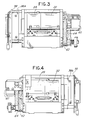
- FIG. 3 is an end view of the shutter of FIG. 1;
- FIG. 4 is an opposite end view of the shutter of FIG. 1;
- FIG. 5 is a side view of the shutter of FIG. 1; showing the motors and drive belts that move the two curtains of the shutter;
- FIG. 6 is a cross-section of the shutter of FIG. 1 taken along the lines 6 — 6 of FIG. 5;
- FIG. 7 is a block diagram of the DSP electronic control system for the shutter of FIG. 1;
- FIG. 8 is an illustration of the position of the curtains of the shutter as a function of time for a cycle of operation of the shutter.
- the top curve shows the position of the leading edge as a function of time and the lower curve shows the position of the trailing edge on the second curtain.
- the gap between the two curves represents the exposure slit between the curtains. The slit is held constant across the format area during the exposure in the illustrated embodiment.
- a shutter is provided comprised of two adjacent curtains, each driven rapidly and simultaneously across the focal plane by separate motors via a series of timing belts and pulleys.
- the scene entering the optical path of the camera is exposed onto the EO imaging array by rapidly moving a slit, which is formed by providing a small separation between the two curtains, across the focal plane.
- the exposure is controlled by carefully adjusting the width of the slit by electronic means based on the required exposure.
- the shutter operation is bi-directional, meaning that the shutter curtains traverse first in one direction across the format area and then in the opposite direction on the next shutter cycle.
- the shutter of the preferred embodiment described below contains many unique features not found in the prior art shutters.
- DSP digital signal processing
- this new shutter design resolves many of the reliability problems and life cycle limitations associated with the prior art shutters, and increases the cycle or frame rate.
- the incorporation of DSP technology allows the exposure to be controlled electronically on a frame by frame basis to accommodate rapidly changing light and scene conditions.
- the shutter contour of operation is also field programmable.
- the shutter is capable of sensing potential curtain damage and has a self-calibrating feature.
- the new shutter is designed to provide increased shutter cycle life and associated MTBF, and to achieve a higher frame rate. This was accomplished by eliminating several high wear, moving mechanical components found in the prior art, including the brush type DC motors, position sensing potentiometers, the gear train that couples the curtain position sensing potentiometer to the motor, and the electromechanical clutch.
- the gear train assembly is eliminated by through the use of a combination motor and resolver for each curtain.
- the resolver is a brushless type and replaces the potentiometer. It is coupled directly to a brushless AC motor to increase position-sensing accuracy. This combination of motor-resolver eliminates the increasing age-related wear and noise from the potentiometer wiper arm and the brushes in the motor, and results in increased shutter performance over the prior art.
- the DSP system as implemented in the shutter design contains a flash memory chip and a field programmable gate array (FPGA) to store and generate many of the parameters pertaining to the operational characteristics of the shutter. These parameters can be changed in the field thereby eliminating the need for the removing and re-programming of EPROM's at the factory, as was necessary with the prior art KS-147 shutter.
- An RS-232 serial communications port is provided on the shutter for connection to a laptop computer.
- Features that can be reprogrammed with the computer in the field include the calibration of the exposure loop or slit width, the curtain velocity, and the shutter cycle rate. The cycle rate can be adjusted without a complete camera system for test purposes.
- the electronic exposure time can also be read out by the computer without the need for additional test equipment.
- the later feature also eliminates the need for manual calibration of the curtain position sensors, as necessary in the prior art.
- the shutter also contains circuitry that monitors the operation of the shutter curtains and automatically shuts down the shutter should the shutter curtains become de-synchronized, or exceed the programmed velocity of 100 inches/second.
- the shutter Upon re-start, the shutter goes through a self-calibration mode re-establishing the curtain positions with respect to each other.
- the camera monitors the current drain of each motor and reports that-data via the RS-232 host communication line.
- the predicted shutter life for the illustrated embodiment is 1,000,000 cycles of operation at 4.0 frames/second with an MTBF of 3 years. This is a very substantial improvement over prior art shutter designs.
- the high cycle life shutter of the illustrated embodiment is designed for a 70 mm format focal plane and although primarily for use with electro-optical (EO) cameras, the shutter can also be used with small format film cameras.
- the shutter operates over an exposure range from 1/1500 second to 1/50 second, is bi-directional, and capable of operating repeatedly at cycle rates up to 7.5 cycles/second.
- the size of the format area is not particularly important, as the shutter can be scaled up for use in larger format reconnaissance cameras such as the five inch KS-87, KS-147, KS-146 etc. for application in either film or larger format electro-optical detectors.
- the shutter can be scaled down to smaller formats. In either case, the DSP system and mechanical design will be applicable to larger and smaller scale implementations than the 70 mm format focal plane in the illustrated embodiment.
- the shutter 20 in accordance with a representative embodiment of the invention includes a frame 22 and a pair of curtains 24 and 26 , which are shown in dashed lines in FIG. 2 in order to better illustrate the rest of the structure of the shutter.
- the curtain 24 is coupled to a pair of roller assemblies 48 A and 46 B.
- the curtain 26 is coupled to a pair of roller assemblies 46 A and 48 B.
- the shutter further includes a first AC motor 28 and integral brushless resolver 32 for the first curtain 24 and a second AC motor 30 and integral brushless resolver 34 for the second curtain 26 .
- the motor 28 rotates a timing pulley 52 causing a timing or drive belt 44 attached to the shaft of the roller assembly 48 A to move the curtain 24 back and forth.
- the motor 30 rotates a timing pulley 50 causing a timing belt 42 attached to the shaft of the roller assembly 46 A to independently move the curtain 26 back and forth.
- the shutter also includes electronics boards 98 and 98 A mounted adjacent to the frame 22 which houses the electronic circuitry for the shutter.
- the electronic circuitry is explained in the block diagram of FIG. 7 below.
- the shutter weighs less than 7.0 pounds in the illustrated embodiment. All mechanical components are designed to operate in environments ⁇ 20° F. to 160° F., high humidity and atmospheric pressures up to 60,000 feet.
- the shutter frame 22 is designed to be compact yet accommodate the 70 mm EO format area.
- the frame 22 is ruggedly designed for use in aircraft environments precisely constructed to allow accurate curtain alignment and fabricated from a common aluminum alloy to give long life and repeatable assembly and disassembly. The design allows easy access components for replacement without removing a module.
- the two drive motors 28 and 30 are mounted to be accessible outside the frame 22 . They independently drive the two curtains 24 and 26 across the format area by using a simple timing belt/pulley system.
- the system is designed to control each curtain 24 , 26 independently and provide long wear life and durability.
- the belt/pulley system is designed to not impose any excess torque to the curtain rollers should a motor develop an uncontrolled runaway condition.
- the two shutter curtains 24 , 26 are made of titanium in the illustrated embodiment and designed for long life, stability, high-speed operation, and durability. Weight is kept to a minimum for maximum motor performance. A special flat black paint mixture is used to coat each curtain to prevent light reflections back into the camera.
- roller assemblies 46 A and 48 A that mount the curtains 24 and 26 are rigid and designed for keeping the two curtains aligned to the image format even at high shutter speeds.
- Rollers 46 B and 48 B contain a differential pivot between two mounting discs to which the curtain legs of the curtains are attached to equalize the tension load on each curtain.
- Each curtain has a spring 60 that is carefully tensioned by the belt/pulley system. This tension is effective but minimized to allow a long curtain life.
- Adjustable belt tensioners 36 , 38 are provided to adjust the tension on the belts 42 , 44 , respectively.
- Each motor has a rotation stop assembly 40 A, 40 B in order to provide initialization for resolver positioning.
- the stop assemblies 40 A, 40 B also limit the number of revolutions the motor could impose on the curtains in order to prevent the curtains from tearing from their mounting points.
- DSP Digital Signal Processor
- the shutter of FIGS. 1-6 includes a DSP feedback control system 100 shown in block diagram form in FIG. 7 .
- the Digital Signal Processing System (DSP) feedback control system 100 consists of the following major components: a TMS320C31 Digital Signal Processor (DSP) 102 , a Field Programmable Gate Array (FPGA) 104 , Complex Programmable Logic Device (CPLD) 106 , an Analog-to-Digital Converter (ADC) 108 , a Flash memory chip 110 , a Digital-to Analog converter (DAC) 112 , Two Resolver-to-Digital Converter (RDC) modules 114 and 116 , and Static Random Access Memory (SRAM) chips 118 .
- the components are connected to each other by a high-speed digital bus system 120 .
- the primary job of the DSP system 100 is to function as a programmable digital controller to accurately control the operation of the high life cycle shutter 20 of FIG. 1 .
- the DSP system 100 replaces all operational amplifiers, resistors, capacitors, FET switches, and potentiometers found in the prior art KS-147 shutter with a numeric processor, memory, analog-to-digital converters and digital-to-analog converters.
- the compensation transfer function for the shutter is implemented in software as digital filters with the coefficients stored in memory.
- High resolution is provided in the ADC, the DAC, and the data word length as represented inside the numeric processor.
- the precision of the floating point of data representation is maintained as the data is filtered through the compensators without the need for scaling factors. This also makes software development much easier.
- the transfer function is also represented more precisely by use of the floating-point representation.
- the floating-point digital signal processor has a 32-bit word length of which the mantissa is 24 bits. This implies 7 decimal digit resolution on all parameters, or 0.00001%.
- the sample time another critical aspect of the control system, has been selected so the amount of phase shift caused by the sampling process is negligible in the frequency band of interest.
- FPGA Field Programmable Gate Array
- the primary functions of the FPGA 104 are to give DSP 102 access to control the ADC data interface 108 , provide the DSP 102 with the access to resolvers for the motors, provide for RS-232/RS-422 communication serial data interface through a UART interface implemented inside the FPGA 104 , and obtain additional digital inputs.
- CPLD Complex Programmable Logic Device
- the primary functions of the CPLD 106 are to generate chip selects for DSP peripheral devices, wait-state generation, and interrupt control.
- the CPLD is vital since it is able to execute at high speeds.
- the flash memory 116 is organized as 524,288 Kbytes of 8 bits each.
- the flash memory 110 is important since it boots the DSP system 100 and allows rapid, in-circuit programming for all application software programs from an external source.
- Analog to Digital Converter (ADC) 108 Analog to Digital Converter
- the ADC 108 has 12-bit resolution and 8 analog input channels. It is used to convert the analog inputs from the motors (motor current reference and motor current) and a exposure control light sensor analog signal to digital inputs so that the DSP 102 can process them.
- DAC Digital to Analog Converter
- the DAC 112 changes digital signals for the motors into analog signals.
- the DAC chip has four separate 12-bit voltage outputs that provide current reference signals to the power amplifiers (not shown) which drive the shutter motors 28 and 30 .
- Resolver to Digital Converter (RDC) modules 114 and 116 are Resolver to Digital Converter (RDC) modules 114 and 116 :
- the resolvers 32 and 34 are motor shaft position sensors, which provide an accurate measurement of the curtain positions which allow a given exposure to be achieved. Since the resolvers turn multiple resolutions they must be homed at power up.
- the resolvers 32 and 34 provide sin and cosine analog position signals to an amplifier 130 .
- An analog to digital converter 132 converts the amplified analog position signal to a digital representation for use by the DSP 102 .
- the resolvers 32 and 34 are brushless devices coupled to the back of each motor. The resolvers measure the position of the shaft of the motor. Since the motors 28 , 30 are coupled to the curtains 24 , 26 via the drive belts 42 and 44 (see FIGS. 1 and 2 ), the resolvers 32 , 34 accurately and independently determine the position of each of the two curtains.
- SRAM Static Random Access Memory
- the (SRAM) provides the program and data memory for execution by the DSP 102 .
- the smooth motion of the curtains is achieved by monitoring the resolver 32 , 34 outputs through resolver-to-digital converters (RDC) modules 114 and 116 and summing these outputs with motor current flow reference signals digitized by an analog to digital converter (ADC) 108 to make an effective position control system.
- the DSP program software is stored in the flash memory 110 , and executed by the DSP processor 102 in conjunction with the SRAM 118 to control the curtains 24 and 26 .
- Pulse width modulation (PWM) signals generated by the DSP software and FPGA 104 are outputted from a digital to analog converter (DAC) 112 to drive the each motor 28 , 30 and shutter curtain 24 , 26 independently.
- the current supplied to the shutter motors 28 , 30 controls the acceleration, deceleration and stopping of the shutter curtains as programmed in accordance with the shutter contour profile of FIG. 8 .
- the camera shutter is able to perform very efficiently because of the digital processing software program that is executed by the DSP system hardware.
- the FPGA 104 is configured, allowing the DSP system 100 to boot from the Flash memory EPROM 110 .
- the shutter operation software program is then loaded into the Static Random Access Memory (SRAM) 118 for execution by the DSP processor chip 102 .
- SRAM Static Random Access Memory
- the system initializes and conditions the I/O signals as needed to perform the shutter operations.
- Digital signals from the ADC at 108 are inputted to the FPGA 104 while analog signals such as motor currents, current references, and light sensor data are received and converted to digital signals before being sent to the DSP processor 102 for processing.
- the software commands the DSP 102 to calculate a sine-squared function signal to start the curtain movement according to the programmed shutter contour profile parameters.
- These signals enable the motors, using pulse-width-modulation (PWM) technology, to drive the curtains to the prescribed contour.
- PWM pulse-width-modulation
- the curtains accelerate to a velocity of 100 inches per second in the initial time period 200 , maintain the 100 inches per second velocity across the exposure format area during the time period 202 , and then decelerate to a stopping point at the other end of the curtain travel during time period 204 .
- the output of an exposure control camera light sensor (not shown) is read and inputted to the ADC of FIG.
- the slit width between the curtains is adjusted by the DSP system 100 to control the exposure.
- the exposure control accommodates changing light conditions of the scene viewed by the camera.
- the acceleration and deceleration profiles 200 and 204 are designed to put minimum stress on the shutter mechanism and curtains yet achieve a cycle period that enables the shutter to cycle at rates of up to 7.5 cycles per second.
- the DSP obtains signals from the light sensor via the A/D converter of FIG. 7 and determines whether the exposure slit size should be adjusted based on scene illumination. If so, the shutter width is automatically changed. In the next cycle of the shutter, the new slit width is observed. Therefore, the camera possesses the ability to change the shutter exposure width after every frame. In contrast, prior art shutters typically averaged exposure levels from multiple exposures and did not have the ability to change the slit width for every exposure.
- the FPGA 104 of FIG. 7 with external access to a technician's computer via the RS-232 interface allows the shutter to be programmable in the field. This is a major advantage over prior art shutters, which required the removal and reprogramming of a EPROM chip. Additionally, the programming of the shutter can be done on the shutter alone, and does not require the entire camera assembly to be physically attached to or with the shutter. Thus, contour profile, frame rate, cycle rate and other shutter parameters can be easily and simply programmed in the field. Or, alternatively, the shutter can be removed from the camera and these parameters set or reprogrammed in the shop via the RS-232 interface.
- the DSP system 100 detects the velocity of the shutter via the resolver signals from the A/D converter.
- the DSP system can thus detect whether the speed of the shutter curtains exceeds a preset limit, such as for example 100 inches per second. Exceeding such a velocity may damage very expensive items such as the curtains.
- the DSP system can be programmed to shut down the curtain motors or otherwise govern their operation in the event of a runaway condition or other malfunction, thereby preventing further damage to the shutter.
- the shutter of the present invention can be used in a variety of types of cameras, including film or electro-optical cameras.
- One example is an electro-optical cameras having a square or rectangular format or detector area with 4 million, 25 million or perhaps 80 million individual pixel elements.
- the precise control of the shutter slit makes the subject shutter also well suited for cameras in which precise shutter motion is helpful for achieving forward motion compensation electronically, such as described in the patents of Hoagland, U.S. Pat. No. 6,108,032 or Mathews et al., U.S. Pat. No. 6,256,057.
- the details of the shutter such as the coupling of the curtains to the roller assemblies, the curtain construction, and various other mechanical details and details on the DSP control system are not considered especially important or critical to the invention. Such details are disclosed for the purposes of illustration of a presently preferred embodiment, and are not intended to be limiting of the scope of the invention.
Abstract
Description
Claims (8)
Priority Applications (4)
| Application Number | Priority Date | Filing Date | Title |
|---|---|---|---|
| US09/976,401 US6510282B1 (en) | 2001-10-11 | 2001-10-11 | Long-life focal plane shutter for reconnaissance cameras |
| AU2002336481A AU2002336481A1 (en) | 2001-10-11 | 2002-09-10 | Long-life focal plane shutter for reconnaisssance cameras |
| PCT/US2002/028896 WO2003032075A2 (en) | 2001-10-11 | 2002-09-10 | Long-life focal plane shutter for reconnaisssance cameras |
| GB0410477A GB2396924B (en) | 2001-10-11 | 2002-09-10 | Long-life focal plane shutter for reconnaisssance cameras |
Applications Claiming Priority (1)
| Application Number | Priority Date | Filing Date | Title |
|---|---|---|---|
| US09/976,401 US6510282B1 (en) | 2001-10-11 | 2001-10-11 | Long-life focal plane shutter for reconnaissance cameras |
Publications (1)
| Publication Number | Publication Date |
|---|---|
| US6510282B1 true US6510282B1 (en) | 2003-01-21 |
Family
ID=25524055
Family Applications (1)
| Application Number | Title | Priority Date | Filing Date |
|---|---|---|---|
| US09/976,401 Expired - Lifetime US6510282B1 (en) | 2001-10-11 | 2001-10-11 | Long-life focal plane shutter for reconnaissance cameras |
Country Status (4)
| Country | Link |
|---|---|
| US (1) | US6510282B1 (en) |
| AU (1) | AU2002336481A1 (en) |
| GB (1) | GB2396924B (en) |
| WO (1) | WO2003032075A2 (en) |
Cited By (8)
| Publication number | Priority date | Publication date | Assignee | Title |
|---|---|---|---|---|
| GB2392325A (en) * | 2002-08-21 | 2004-02-25 | Visteon Global Tech Inc | Actuator for driving a driven member |
| US20050083001A1 (en) * | 2003-10-15 | 2005-04-21 | Asia Optical Co., Inc. | Adjustable iris-diaphragm controller |
| US20050135726A1 (en) * | 2003-12-19 | 2005-06-23 | Industrial Technology Research Institute | Array optical subassembly for array optical active component |
| US7071947B1 (en) * | 2003-07-24 | 2006-07-04 | Nvidia Corporation | Automatic adjustment of floating point output images |
| US20080152335A1 (en) * | 2006-12-21 | 2008-06-26 | Canon Kabushiki Kaisha | Mechanical shutter control method and image sensing apparatus |
| US20100277587A1 (en) * | 2006-11-30 | 2010-11-04 | Visionmap Ltd. | Digital mapping system based on continuous scanning line of sight |
| US20110140689A1 (en) * | 2009-12-10 | 2011-06-16 | Fernando Lalinda D | Signal amplitude adjustment to improve resolver-to-digital converter performance |
| DE102007027401B4 (en) * | 2006-06-12 | 2012-03-08 | Samsung Electro - Mechanics Co., Ltd. | Apparatus for automatically controlling the exposure of an image sensor |
Citations (7)
| Publication number | Priority date | Publication date | Assignee | Title |
|---|---|---|---|---|
| US2713814A (en) | 1947-07-15 | 1955-07-26 | Chicago Aerial Survey Co | Aircraft camera |
| US4235546A (en) * | 1978-03-31 | 1980-11-25 | Woodfine Clive F | Photographic camera system and a focal plane photographic camera shutter system |
| US4505559A (en) * | 1983-04-20 | 1985-03-19 | Carl-Zeiss-Stiftung, Heidenheim/Brenz | Method and means for compensating for image motion in an aerial camera |
| US4664494A (en) | 1986-01-28 | 1987-05-12 | Recon/Optical, Inc. | Electronic focal plane shutter |
| US6108032A (en) | 1996-11-05 | 2000-08-22 | Lockheed Martin Fairchild Systems | System and method for image motion compensation of a CCD image sensor |
| US6256057B1 (en) | 1996-11-05 | 2001-07-03 | Lockhead Martin Corporation | Electro-optical reconnaissance system with forward motion compensation |
| US6336752B1 (en) | 1999-11-19 | 2002-01-08 | Lockheed Martin Corporation | Dual motor reciprocating belt shutter |
-
2001
- 2001-10-11 US US09/976,401 patent/US6510282B1/en not_active Expired - Lifetime
-
2002
- 2002-09-10 WO PCT/US2002/028896 patent/WO2003032075A2/en not_active Application Discontinuation
- 2002-09-10 AU AU2002336481A patent/AU2002336481A1/en not_active Abandoned
- 2002-09-10 GB GB0410477A patent/GB2396924B/en not_active Expired - Fee Related
Patent Citations (7)
| Publication number | Priority date | Publication date | Assignee | Title |
|---|---|---|---|---|
| US2713814A (en) | 1947-07-15 | 1955-07-26 | Chicago Aerial Survey Co | Aircraft camera |
| US4235546A (en) * | 1978-03-31 | 1980-11-25 | Woodfine Clive F | Photographic camera system and a focal plane photographic camera shutter system |
| US4505559A (en) * | 1983-04-20 | 1985-03-19 | Carl-Zeiss-Stiftung, Heidenheim/Brenz | Method and means for compensating for image motion in an aerial camera |
| US4664494A (en) | 1986-01-28 | 1987-05-12 | Recon/Optical, Inc. | Electronic focal plane shutter |
| US6108032A (en) | 1996-11-05 | 2000-08-22 | Lockheed Martin Fairchild Systems | System and method for image motion compensation of a CCD image sensor |
| US6256057B1 (en) | 1996-11-05 | 2001-07-03 | Lockhead Martin Corporation | Electro-optical reconnaissance system with forward motion compensation |
| US6336752B1 (en) | 1999-11-19 | 2002-01-08 | Lockheed Martin Corporation | Dual motor reciprocating belt shutter |
Non-Patent Citations (4)
| Title |
|---|
| Air Force T.O. 10A1-5-29-2 Technical Manual, Service Instructions, Camera Set, Still Picture, Type KS-87B, Type KS-87D (May 19, 1989). |
| CAI Brochure, "KA-96A 24-inch FL Frame Camera" (circa 1980). |
| CAI Brochures, "KS-87B Aerial Reconnaissance Camera" (Nov. 1978). |
| Navy Air Systems Command, Technical Manual, Operation and Intermediate Maintenance with Illustrated Parts Breakdown, KS-153A Still Picture Camera Set (Nov. 1, 1988). |
Cited By (13)
| Publication number | Priority date | Publication date | Assignee | Title |
|---|---|---|---|---|
| GB2392325B (en) * | 2002-08-21 | 2004-08-18 | Visteon Global Tech Inc | Actuator for driving a driven member |
| GB2392325A (en) * | 2002-08-21 | 2004-02-25 | Visteon Global Tech Inc | Actuator for driving a driven member |
| US7071947B1 (en) * | 2003-07-24 | 2006-07-04 | Nvidia Corporation | Automatic adjustment of floating point output images |
| US20050083001A1 (en) * | 2003-10-15 | 2005-04-21 | Asia Optical Co., Inc. | Adjustable iris-diaphragm controller |
| US6922030B2 (en) * | 2003-10-15 | 2005-07-26 | Asia Optical Co., Inc. | Adjustable iris-diaphragm controller |
| US20050135726A1 (en) * | 2003-12-19 | 2005-06-23 | Industrial Technology Research Institute | Array optical subassembly for array optical active component |
| DE102007027401B4 (en) * | 2006-06-12 | 2012-03-08 | Samsung Electro - Mechanics Co., Ltd. | Apparatus for automatically controlling the exposure of an image sensor |
| US10337862B2 (en) | 2006-11-30 | 2019-07-02 | Rafael Advanced Defense Systems Ltd. | Digital mapping system based on continuous scanning line of sight |
| US20100277587A1 (en) * | 2006-11-30 | 2010-11-04 | Visionmap Ltd. | Digital mapping system based on continuous scanning line of sight |
| US20080152335A1 (en) * | 2006-12-21 | 2008-06-26 | Canon Kabushiki Kaisha | Mechanical shutter control method and image sensing apparatus |
| US7753601B2 (en) * | 2006-12-21 | 2010-07-13 | Canon Kabushiki Kaisha | Mechanical shutter control method and image sensing apparatus |
| US20110140689A1 (en) * | 2009-12-10 | 2011-06-16 | Fernando Lalinda D | Signal amplitude adjustment to improve resolver-to-digital converter performance |
| US8274414B2 (en) * | 2009-12-10 | 2012-09-25 | Analog Devices, Inc. | Signal amplitude adjustment to improve resolver-to-digital converter performance |
Also Published As
| Publication number | Publication date |
|---|---|
| GB0410477D0 (en) | 2004-06-16 |
| AU2002336481A1 (en) | 2003-04-22 |
| GB2396924A (en) | 2004-07-07 |
| GB2396924B (en) | 2004-12-22 |
| WO2003032075A3 (en) | 2003-11-06 |
| WO2003032075A2 (en) | 2003-04-17 |
Similar Documents
| Publication | Publication Date | Title |
|---|---|---|
| US6510282B1 (en) | Long-life focal plane shutter for reconnaissance cameras | |
| EP0665694B1 (en) | High resolution film scanner | |
| US20060257129A1 (en) | Image sensing apparatus equipped with anti-shake mechanism | |
| US5541693A (en) | Blur correcting apparatus and method for a camera | |
| GB1594653A (en) | Copy camera having automatic focusing | |
| US6850021B1 (en) | Precision virtual encoder | |
| US6169571B1 (en) | Film scanning apparatus with motorized weave correction | |
| JP4218964B2 (en) | LENS DEVICE AND IMAGING DEVICE | |
| US20020118966A1 (en) | Zoom and focus control system in an optical system | |
| EP1058105B1 (en) | Measuring drive train backlash with a restraining member | |
| US4610538A (en) | Color compensation method in photographic printer | |
| JPH1062676A (en) | Drive control device | |
| US4806988A (en) | Process and an arrangement for the automatic focusing in a photographic enlarging or copying apparatus with a variable enlarging scale | |
| GB2269230A (en) | Measuring light wavelength. | |
| US10215635B2 (en) | Data blending multiple dispersive range monochromator | |
| JPH0521207B2 (en) | ||
| Mitsch et al. | Versatile multi-object spectroscopy with FORS at the ESO Very Large Telescope | |
| US4922247A (en) | Encoder mount | |
| JPH04136704A (en) | Position detection device | |
| RU2275665C1 (en) | Aerial camera | |
| US7072126B2 (en) | Temperature compensation device for optical instruments | |
| Lei et al. | Real-time phase-shifting techniques for determining the photoelastic parameters: a theoretical comparison | |
| JP3551464B2 (en) | Adjustment apparatus for shake correction camera, shake correction camera, and adjustment method | |
| JPH07181536A (en) | Camera shake correcting camera | |
| JP4242731B2 (en) | Lens measuring machine |
Legal Events
| Date | Code | Title | Description |
|---|---|---|---|
| AS | Assignment |
Owner name: RECON/OPTICAL, INC., ILLINOIS Free format text: ASSIGNMENT OF ASSIGNORS INTEREST;ASSIGNORS:RUCK, RICHARD C.;MILWEE, JOHN F.;QUINN, JAMES P.;AND OTHERS;REEL/FRAME:012586/0202 Effective date: 20011016 |
|
| AS | Assignment |
Owner name: RECON/OPTICAL, INC., ILLINOIS Free format text: ASSIGNMENT OF ASSIGNORS INTEREST;ASSIGNOR:CHIREMPES, GEORGE;REEL/FRAME:012663/0543 Effective date: 20020122 |
|
| STCF | Information on status: patent grant |
Free format text: PATENTED CASE |
|
| FPAY | Fee payment |
Year of fee payment: 4 |
|
| AS | Assignment |
Owner name: GOODRICH CORPORATION, NORTH CAROLINA Free format text: ASSIGNMENT OF ASSIGNORS INTEREST;ASSIGNOR:RECON/OPTICAL, INC.;REEL/FRAME:021328/0982 Effective date: 20080725 |
|
| FPAY | Fee payment |
Year of fee payment: 8 |
|
| FPAY | Fee payment |
Year of fee payment: 12 |