US6509876B1 - Antenna for wireless communication system - Google Patents
Antenna for wireless communication system Download PDFInfo
- Publication number
- US6509876B1 US6509876B1 US09/657,500 US65750000A US6509876B1 US 6509876 B1 US6509876 B1 US 6509876B1 US 65750000 A US65750000 A US 65750000A US 6509876 B1 US6509876 B1 US 6509876B1
- Authority
- US
- United States
- Prior art keywords
- retractable platform
- antenna
- wireless communication
- communication card
- communication
- Prior art date
- Legal status (The legal status is an assumption and is not a legal conclusion. Google has not performed a legal analysis and makes no representation as to the accuracy of the status listed.)
- Expired - Lifetime
Links
Images


Classifications
-
- H—ELECTRICITY
- H01—ELECTRIC ELEMENTS
- H01Q—ANTENNAS, i.e. RADIO AERIALS
- H01Q1/00—Details of, or arrangements associated with, antennas
- H01Q1/12—Supports; Mounting means
- H01Q1/22—Supports; Mounting means by structural association with other equipment or articles
- H01Q1/2258—Supports; Mounting means by structural association with other equipment or articles used with computer equipment
- H01Q1/2275—Supports; Mounting means by structural association with other equipment or articles used with computer equipment associated to expansion card or bus, e.g. in PCMCIA, PC cards, Wireless USB
-
- H—ELECTRICITY
- H01—ELECTRIC ELEMENTS
- H01Q—ANTENNAS, i.e. RADIO AERIALS
- H01Q1/00—Details of, or arrangements associated with, antennas
- H01Q1/12—Supports; Mounting means
- H01Q1/22—Supports; Mounting means by structural association with other equipment or articles
- H01Q1/24—Supports; Mounting means by structural association with other equipment or articles with receiving set
- H01Q1/241—Supports; Mounting means by structural association with other equipment or articles with receiving set used in mobile communications, e.g. GSM
- H01Q1/242—Supports; Mounting means by structural association with other equipment or articles with receiving set used in mobile communications, e.g. GSM specially adapted for hand-held use
- H01Q1/243—Supports; Mounting means by structural association with other equipment or articles with receiving set used in mobile communications, e.g. GSM specially adapted for hand-held use with built-in antennas
Definitions
- the present invention generally relates to a wireless communication system and, in particular, to a retractable antenna for an electronic communication card that allows wireless communication.
- Computers are often connected to various communication systems to communicate, exchange data, and transmit various types of information.
- computers are often linked by communication systems or networks such as Local Area Networks (LANs), Wide Area Networks (WANs), Internet, Ethernet and conventional telephone networks.
- LANs Local Area Networks
- WANs Wide Area Networks
- Ethernet Ethernet
- These communication systems typically require the computers to be physically attached by wires such as telephone lines or other specialized wiring. In some locations, however, it is difficult if not impossible to be physically connected to a communication system. Additionally, these communication systems generally cannot be used if the user is traveling or moving between locations.
- PCMCIA Personal Computer Memory Card International Association
- cellular telephones and other wireless systems it is also known to use cellular telephones and other wireless systems to connect computers to various communication systems and networks.
- Cellular telephone systems are particularly effective in allowing computers to communicate because the computers do not have to be physically connected to telephone lines or other specialized wiring.
- the computers are connected to the communication system by the cellular telephone network.
- cellular telephone systems are very useful in connection with portable computers because the cellular communication circuitry can be miniaturized and provided as a component of the computer.
- antennas are typically placed external to the body of the computer because of noise, interference, obstruction and shielding caused by the various components of the computer.
- Conventional antennas generally do not function correctly if they are obstructed or shielded by the housing or other structures of the computer.
- Conventional antennas are generally rigid and protrude a relatively long distance from the body of the computer. These protruding antennas are often large, unwieldy, aesthetically unpleasing and they make the computer difficult to move and transport. In addition, these antennas are often bent, broken, knocked out of alignment or otherwise damaged because they can easily catch or strike objects such as people, walls, doors, etc. Further, these known antennas require a large support structure to secure the antenna to the housing of the computer and this support structure requires a considerable amount of space inside the body of the computer. This space is very valuable, especially in small, portable computers. Additionally, the support structure is often damaged when the antenna is accidentally moved.
- conventional antennas are often removed or detached from the computer before it is moved or transported. Additionally, conventional antennas must often be removed before the computer can be inserted into its carrying case. Disadvantageously, this requires additional time and resources to remove and reattach the antenna each time the computer is moved. Additionally, when the antenna is detached from the computer, it is often misplaced, lost or damaged. Further, because the user often does not want to take the time and effort to remove the antenna, the computer is moved with the antenna still attached to the computer and this frequently results in the antenna being damaged or broken.
- U.S. Pat. No. 5,684,672 issued to Karidis, et al. discloses a laptop computer with an integrated multi-mode antenna.
- the telescoping antenna is integrated into the cover or display portion of the laptop computer and it outwardly extends from the display portion for use.
- the telescoping antenna is then retracted into the display portion when it is not in use.
- a coaxial cable connects the antenna to the base of the computer.
- the coaxial cable connects the antenna to a radio frequency (RF) adaptor card inserted into a PCMCIA slot located in the base of the computer.
- RF radio frequency
- the telescoping antenna disclosed in the Karidis patent is large, extends a great distance from the body of the computer, and requires the user to manually extend and retract the antenna.
- U.S. Pat. No. 5,557,288 issued to Kato, et al. discloses a drawer that passes through an opening in the housing of the computer when it is moved between the extended and retracted positions.
- the user When wireless communication is desired, the user must open a door to the opening in the housing, extend the drawer through the opening, and rotate and extend the antenna into the desired position.
- the wireless communication When the wireless communication is finished, the user must rotate and withdraw the antenna into a storage position, retract the drawer into the computer, and close the door to the opening.
- the system disclosed in the Kato patent requires numerous steps by the user before wireless communication can be established, and numerous steps to retract and store the antenna. Further, the device disclosed in the Kato patent requires a large amount of space, which is very valuable in portable or compact computers.
- a disadvantage of these known systems is the antenna is always operable and ready for wireless communication. Thus, inadvertent wireless communication may occur, or wireless communication may occur when it is prohibited. Additionally, the antenna may transmit or receive wireless signals while it is stored inside the computer, which may cause interference and disrupt the operation of the computer.
- Another disadvantage is the antenna system is continually drawing power from the computer. This is especially a problem with portable or smaller-sized computers that have a need for a long-lasting and portable power supply. Because portable computers are often used in environments where access to conventional power supplies are not available, a battery or similar power supply is needed. The electrical storage capability of the battery, however, is generally in direct proportion to its physical size. Thus, in instances where a smaller battery is used, there is a need to conserve the electrical power used by the computer, and any connected peripherals, to lengthen the usable life of the battery.
- the antenna system advantageously provides wireless or radio frequency (RF) communication with other networks or communication systems to allow data and other information to be shared or exchanged.
- the antenna system includes an antenna attached to a retractable platform that is selectably movable between an extended position and a retracted position.
- the retractable platform When wireless communication is desired, the retractable platform is located in the extended or use position and the antenna is substantially disposed outside of the body of the communications card.
- the retractable platform and antenna are stored inside the body of the communications card in the retracted or stored position. This stored position protects the retractable platform and antenna from damage.
- the antenna can be quickly and easily positioned in the extended position for use, and it can be simply and promptly placed in the stored position when wireless communication is not desired.
- Another aspect is an antenna system in which wireless communication is unavailable or inoperative when the retractable platform is in the storage position.
- Wireless communication is available and operable when the retractable platform is in the extended position.
- the antenna system is automatically operable and ready for use in the extended position, and is automatically inoperable in the storage position. That is, the antenna system is automatically turned on or enabled in the extended position, and turned off or not enabled in the storage position. Desirably, this process occurs without any intervention by the user other than to extend or retract the retractable platform.
- control mechanism such as a switch, that controls whether wireless communication is available or operable.
- the control mechanism is used to prohibit operation of the antenna system during selected periods.
- the control mechanism controls the ability of the antenna system to operate based upon the positioning of the retractable platform and by controlling the supply of electrical power to the antenna system.
- the antenna system advantageously saves power and/or battery life by being turned off in the storage position. Additionally, by preventing use of the antenna or wireless system in the storage position, this may comply with future Federal Aviation Administration (FAA) or Federal Communication Commission (FCC) requirements that wireless communication not be permitted in certain locations or during specific times. For example, wireless communication may not be permitted on airplanes, in hospitals, at construction sites, within high security buildings, or at other sensitive or protected areas. Thus, by simply storing the retractable platform in the storage position, wireless communication is not permitted.
- the other features of the communication card and/or computer may still be usable even though wireless communication is not possible. Thus, the user may continue to use the communication card and/or computer, even though wireless communication is not permitted.
- a pilot or flight attendant could quickly and easily ensure that wireless communication is not possible, even though the computer or electronic device is still operable.
- a visual indicator or other signal may also be used to confirm that the wireless communication feature is disabled.
- Still another aspect of the antenna system is a mechanism for retracting the antenna into the storage position when wireless communication is not desired and deploying the antenna when wireless communication is desired.
- the mechanism used to extend and retract the antenna is a retractable platform that is movable between an extended portion and a retracted position.
- the antenna is desirably attached to the outer portion of the retractable platform such that it is located a sufficient distance from the body of the computer in the extended position. This optimizes the reception of the antenna because the computer or communication card can block, shield or interfere with the wireless signal.
- the antenna is not transmitting signals or causing RF interference within the electronic device. This may help improve the performance of the electronic device.
- the communication card includes a retractable platform and at least an antenna is mounted to the platform.
- the circuitry or other components necessary for wireless communication are located in the communication card and/or the retractable platform.
- the antenna system is an integral part of the communication card, the card can be quickly and easily connected to various suitable electronic devices, and the card can be used interchangeably with other devices. This increases the flexibility and potential uses of the antenna system and communication card.
- the antenna or antenna system can also be removably attached to the communication card or other suitable electronic device to allow different antennas to be attached and facilitate repair.
- antenna system that can be optimized for use with a particular wireless system.
- the antenna can be configured to receive or transmit specifically on the frequencies of the desired wireless communication system.
- the antenna system is an indicator that is attached to the retractable platform or communication card.
- the indicator is preferably a light source that indicates use of the antenna system or that wireless communication is available.
- the indicator can also indicate that the antenna system or wireless communication is not available or inoperable.
- the indicator may also be used to indicate other information such as power, status, diagnostics, etc.
- the antenna and its associated components are very small and compact, it has minimum size and space requirements. Accordingly, the antenna system can be easily attached to the retractable platform and/or communication card, and it requires only a small space. This significantly decreases design and manufacturing costs.
- a preferred embodiment is an apparatus that controls the operational state of the antenna system based upon the positioning of the retractable platform.
- the antenna is attached to the retractable platform and the platform is selectively movable between an extended position and a retracted position.
- Wireless communication is enabled when the retractable platform is in the extended position, but wireless communication is not available in the retracted position.
- a control mechanism is used to determine if wireless communication is available.
- the control mechanism may only provide electrical power to the antenna system in the extended position and not the retracted position.
- the control mechanism for example, may include a switch, optical sensor, or electrical contacts to control whether wireless communication is possible.
- the antenna system may be selectively powered, this can greatly reduce the amount of electrical power used by the host device, which thereby increase its useful battery life.
- the antenna system cannot be used to transmit or receive wireless signals when the platform is retracted, the computer and/or communication card may still be used.
- Another preferred embodiment is an antenna system mounted to a retractable platform that is moveable between an extended position and a retracted position. Extension of the retractable platform causes a control mechanism to indicate that the antenna system is “ready for use.” This status will be supplied to an appropriate control circuit. For instance, the control circuit can supply electrical power to the antenna system to enable wireless communication. When the connector is retracted, the control mechanism indicates that the antenna system is “inoperative or not usable.” Accordingly, the control circuit could, for example, cut off or limit the electrical power that is supplied to the antenna system such that the antenna system could not be used for wireless communication.
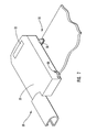
- FIG. 1 is a perspective view of a portable computer and a communication card, illustrating a preferred embodiment of the retractable platform and antenna system;
- FIG. 2 is a perspective view of a preferred embodiment of the antenna system, with a control mechanism including a mechanical switch, illustrating the retractable platform in the extended position;
- FIG. 3 is a perspective view of the antenna system shown in FIG. 2, illustrating the retractable platform in the retracted position;
- FIG. 4 is a perspective view of another preferred embodiment of the antenna system, with a control mechanism including an optical system, illustrating the retractable platform in the extended position;
- FIG. 5 is a perspective view of the antenna system shown in FIG. 4, illustrating the retractable platform in the retracted position;
- FIG. 6 is a perspective view of yet another preferred embodiment of the antenna system with a control mechanism including an electrical system, illustrating the retractable platform in the extended position;
- FIG. 7 is a perspective view of the antenna system shown in FIG. 6, illustrating the retractable platform in the retracted position
- FIG. 8 is a block diagram of a preferred embodiment of the antenna system, illustrating the retractable platform in an extended position
- FIG. 9 is a block diagram showing another preferred embodiment of the antenna system, illustrating the retractable platform in a retracted position
- FIG. 10 is a cross-sectional top view of a preferred embodiment of the retractable platform, illustrating a preferred switching arrangement
- FIG. 11 is a cross-sectional top view of another preferred embodiment of the retractable platform, illustrating another preferred switching arrangement
- FIG. 12 is a cross-sectional top view of still another preferred embodiment of the retractable platform, illustrating yet another alternative preferred switching arrangement.
- FIG. 13 is a cross-sectional top view of a further preferred embodiment of the retractable platform, illustrating another preferred switching arrangement.
- the present invention involves an antenna system for use with an electronic device such as a communication card.
- the communication card is preferably used in connection with a computer, such as a portable or laptop computer, but it will be understood that the computer may be any suitable type of general or special purpose computer.
- the principles of the present invention are not limited to communications cards or computers. It will be understood that, in light of the present disclosure, the antenna system disclosed herein can be successfully used in connection with other types of electronic devices.
- FIG. 1 illustrates a portable computer 10 with an antenna system 12 in accordance with a preferred embodiment of the present invention.
- the term portable computer 10 is used broadly to describe any suitable computer such as a personal computer, laptop computer, notebook computer, hand-held computer, palm computer or other type of computer with suitable characteristics.
- the antenna system 12 can also be used with other electronic devices such as cellular telephones, digital communication systems, personal data assistants (PDAs), electronic organizers, GPS systems, wireless communication systems, and the like.
- PDAs personal data assistants
- the antenna system 12 can also be used with other devices that may benefit from the ability to communicate over wireless networks such as television sets, digital telephones, automotive electronics, etc.
- the portable computer 10 includes one or more slots 14 (two exemplary slots are shown in FIG. 1) for detachably receiving a communication card 16 .
- the communication card 16 includes a first end 18 that is inserted into the slot 14 and a second end 20 that is located generally parallel to an outer surface of the computer 10 when the card is inserted into the slot. Disposed along the first end 18 of the card 10 is an edge connector (not shown) that is designed to electrically communicate with a corresponding socket located in the slot 14 .
- the slot 14 and communication card 16 preferably comply with applicable Personal Computer Memory Card International Association (PCMCIA) standards.
- PCMCIA Personal Computer Memory Card International Association
- the PCMCIA standards for example, are described in detail in the PCMCIA Specification Standards, which are hereby incorporated by reference.
- PCMCIA Specification Standards provide standards for data storage, peripheral expansion cards, input/output (I/O) capability for a standard bus extension slot so that peripherals such as modems and LAN adapters can use the bus and other related information. It will be understood, however, that while the communication card 16 is described with respect to PCMCIA standards, the antenna system 12 may be used with virtually any type of communication card or electrical device. Additionally, while the communication card 16 is preferably a miniature type, any suitable size and type of card may be used.
- the computer 10 includes a body or housing 22 that includes a cover or upper portion 24 and a base or lower portion 26 . Located within the base 26 are various known computer circuitry components such as processing units, printed circuit boards and memory storage devices. One skilled in the art will understand that the computer 10 may include various components depending, for example, upon the type and configuration of the computer.
- the computer 10 also includes circuitry and components that allow electrical communication to be established with a communication card 16 inserted into the slot 14 .
- the communication card 16 may also include circuitry and components that allow electrical communication with the computer 10 .
- the communication card 16 includes a retractable platform 30 with one or more antennas 32 , and disposed within the communication card is circuitry that provides an interface between the card and the antenna.
- the circuitry contained within the communication card 16 may include, for example, a printed circuit board and may provide processing such as RF signal processing and/or baseband processing.
- the communication card 16 and/or computer 10 may also include a power source such as a battery or other device to provide power to the antenna system 12 , but it will be understood that the antenna system may receive power from any suitable source.
- the antenna system 12 includes the antenna 32 and some, if not all, of the circuitry and components required for wireless communication.
- the antenna system 12 may include impedance matching circuitry, ground plane, etc., and some or all of this circuitry and/or components may be disposed on the retractable platform 30 or within the communication card 16 .
- the antenna 32 may include any suitable number or types of radiating elements, and the antenna and antenna system 12 are preferably optimized for specific use at a given frequency.
- the antenna 32 may be dimensioned and the components of the antenna system 12 may be constructed to optimize RF reception and transmission at frequencies within the frequency bands of the wireless system.
- the antenna 32 and antenna system 12 may be optimized for use with a wide variety of electronic devices.
- the antenna 32 and antenna system 12 are configured to allow communication with a wireless communications network.
- the wireless communications network may include wireless modems, wireless LAN, wireless Personal Area Network (PAN), cellular telephone networks, digital communication systems, etc.
- the wireless communication network may also include low-powered or short-range radio systems, such as Bluetooth systems that allow products containing Bluetooth technology to be interconnected via wireless communication.
- the antenna 32 is preferably a chip or strip type antenna, but any suitable type of antenna may be used depending upon factors such as desired polarization and radiation patterns, or type of wireless communication system. Additionally, the antenna 32 and antenna system 12 are preferably configured for optimized use with a particular wireless communication system. For example, antenna 32 and the antenna system 12 may be configured to conform to applicable Bluetooth technology specifications and standards, which allows the computer 10 to be connected to a wide range of computing and telecommunication devices via wireless connections. Thus, the antenna 32 would be configured to use the Industrial Scientific and Medical (ISM) frequency band of 2.4 to 2.4835 gigahertz (GHz).
- ISM Industrial Scientific and Medical
- Bluetooth Special Interest Group SIG
- the antenna 32 and antenna system 12 can be used with any suitable wireless communication system.
- the retractable platform 30 is movable between an extended position and a retracted position 36 .
- the retractable platform 30 is preferably similar to the retractable devices described and illustrated in U.S. Pat. Nos. 5,183,404; 5,338,210; 5,547,401; 5,727,972; and pending U.S. patent application Ser. No. 09/357,017, each of which are hereby incorporated by reference.
- retractable devices described and illustrated in U.S. Pat. No. 5,562,504 or co-pending United States application Ser. No. 09/271,620, which are also hereby incorporated by reference could be utilized. It will be appreciated, however, that any retractor platform with suitable characteristics could be used in conjunction with the antenna 32 or antenna system 12 .
- the retractable platform 30 is selectively movable between an extended position 34 and a retracted position 36 , respectively.
- the antenna 32 is at least substantially disposed external to the communication card 16 in order to minimize interference, obstruction, noise, etc.
- the antenna 32 is located at such a distance that it minimizes interference with the communication card and the host device, such as the computer 10 .
- the retractable platform 30 and the antenna 32 are substantially disposed within the body of the communication card 16 .
- Wireless communication is only enabled or operable when the retractable platform 30 is disposed in the extended position 34 , and wireless communication is not available or possible when the retractable platform 30 is in the retracted position 36 .
- operation of the wireless communication is controlled by the positioning of the retractable platform 30 .
- only the wireless communication feature is inoperable or not enabled when the retractable platform 30 is in the retracted position, but the entire communication card 16 may be inoperable or not enabled.
- the operation of the wireless communication system is preferably automatically controlled according to the positioning of the retractable platform 30 .
- the user does not have to take any additional steps or procedures to enable or disable wireless communication.
- the user may manually select whether wireless communication is enabled.
- a control mechanism 38 is used to control when wireless communication is available or operable.
- the control mechanism 38 may use various methods to determine or sense the positioning of the retractable platform 30 .
- the control mechanism 38 may comprise a mechanical switch 40 that is used to turn the wireless communication on or off.
- the mechanical switch 40 includes an engagement section 42 that is configured to contact or engage an outwardly projection portion 44 of the retractable platform 30 .
- the projecting portion 44 does not engage the engagement section 42 when the platform is in the extended position and wireless communication is permitted.
- the engagement section 42 contacts the projecting portion 44 and wireless communication is not permitted.
- switches such as toggle, contact or leaf or spring switches, may be utilized, and the switches may have various configurations such as indicating when the retractable platform 30 is in the retracted position.
- the control mechanism 38 may use an optical or light-based system 46 to determine the positioning of the retractable platform 30 , and that determines if wireless communication is operable or inoperable.
- the optical system 46 includes a light source 48 , a reflective surface 50 and a detector 52 .
- the light source 48 is connected to a portion of the communication card 16 , such as a PCB 54 , and it directs light towards the reflective surface 50 of the retractable platform 30 .
- the light is reflected by the reflective surface 50 and it is received by the detector 52 .
- the optical system 46 determines the location of the retractable platform 30 , and the operational state of wireless communication is based upon the positioning of the platform. For example, when the detector 52 does not detect light from the light source 48 , that indicates that the tractable platform is in the retracted position and wireless communication should not be available.
- the optical system 46 could include various components such as light emitting diodes (LEDs), light sensing diodes, light pipes, etc. to determine the positioning of the retractable platform 30 .
- the control mechanism 38 may also utilize an electrical system 56 to determine the positioning of the retractable platform 30 .
- the electrical system 56 may include electrical contacts 58 attached to the communication card 16 that are capable of being in electrical communication with corresponding electrical pads 60 on the retractable platform 30 .
- the electrical contacts 58 are in electrical communication with the electrical pads 60 .
- the electrical system 56 has determined that the retractable platform 30 is in the extended position 34 and wireless communication should be enabled.
- the electrical contacts 58 and pads 60 are not in the electrical communication, that indicates that the retractable platform 30 is in the retracted position 36 . It will be understood that a wide variety of electrical components and systems may be used to determine the positioning of the retractable platform 30 .
- the control mechanism 38 is preferably attached to the communication card 16 and the movement of the retractable platform 30 is transmitted to the control mechanism over the line 62 .
- the physical movement of the retractable platform 30 operates a switch mechanism 64 that is connected to a control circuit 66 .
- the control mechanism 38 causes the switch mechanism 64 , as shown in FIG. 8, to move to a predetermined position 68 that indicates an “in use” status signal to be supplied to a control circuit 66 .
- the switch mechanism 64 indicates that the antenna system 12 should be capable of transmitting and receiving wireless signals, and the control circuit 66 causes electrical power to be supplied to the antenna system 12 .
- control circuit 66 may be an extension of the power pin on the edge connector of communication card 16 that is used to receive electrical power from the host computer, which is merely placed in a closed position to permit the flow of electrical current (or similar power supply arrangement) to the antenna system 12 . It will be appreciated that while the illustrated control circuit is used to control the supply of electrical power, it could be implemented to control other types of operational parameters as well.
- FIG. 9 illustrates the retractable platform 30 in the retracted position 36 .
- This position causes the switch mechanism 64 to assume a “not in use” status signal, which causes the control circuit 66 to disengage electrical power from being received by the antenna system 12 .
- an arrangement may be utilized whereby only a limited amount of power is supplied to the antennal system, but power to the entire communication card could be left on or turned off.
- switch mechanism 64 can also include various other mechanical, optical, magnetic, proximity or other switching technologies that are well known in the art, some of which are described below. Also, while the illustrated embodiment in those figures contemplates actuation of the switch mechanism 64 via the physical retraction and extension of the retractable platform 30 , actuation could also be manually invoked by the user.
- FIGS. 10 through 13 which illustrate various embodiments for implementing the switch mechanism 64 described above.
- FIG. 10 is a cross-sectional view of a preferred embodiment of the retractable platform 30 and antenna 32 .
- the retractable platform 30 which is shown in the extended position 34 , is mounted on slide rails 70 so that the platform can be retracted within the housing of the card 16 .
- a spring 72 or a similar biasing means can be used to aid in the extension of the platform 30 .
- a latch mechanism 74 or similar type of retention mechanism, can be used in conjunction with receiving tabs 76 and 78 to assist in maintaining the position of the platform 30 in either an extended or a retracted position.
- the switch mechanism 64 is an optical switch arrangement that includes a photo detector emitter device 80 and a corresponding reflective surface 82 that is formed on an outer surface of the retractable platform 30 .
- the photo detector emitter 80 will detect the corresponding position of the reflective surface 82 .
- the photo detector emitter 80 will then generate an “in use” status signal via schematic line 84 .
- This signal is in turn supplied to a corresponding control circuit, such as a power control circuit as discussed above. In this position, the power control circuit will permit electrical power to flow to the antenna system 12 .
- An indicator such as a light source 83
- a light source 83 may be disposed on the retractable platform 30 and lit when the platform is in the extended position 34 to indicate that the antenna system 12 is operational.
- the indicator could alternatively be used to indicate other information such as power, status, diagnostics, etc. Though described here as a light source, the indicator could comprise any one of a variety of signals. Also, the indicator could alternatively be disposed on the communication card 16 , or even the antenna 32 itself.
- FIG. 11 which illustrates another presently preferred embodiment for the switch mechanism 64 that is actuated via movement of the retractable platform 30 .
- a mechanical switch arm 86 is positioned to engage a lower surface 88 of the retractable platform 30 when it is in the retracted position 36 .
- the mechanical switch arm 86 is positioned such that when the platform 30 is retracted, the surface 88 will abut against a portion of the switch arm 86 so as to depress the switch and thereby actuate it into a closed position.
- a corresponding “in use” signal will be generated and supplied via schematic line 90 to an appropriate control circuit.
- the retractable platform 30 will cause the switch arm 86 to be moved to a closed position and thereby generate a “not in use” status signal. In this case, wireless communication will not be permitted.
- FIG. 12 illustrates still another preferred embodiment with a conductive shorting bar 92 positioned at the lower end of the retractable platform 30 .
- a pair of electrical contacts 94 is in an open position when the retractable platform 30 is in the extended position 34 , as shown in the accompanying figure. This state corresponds with a “in use” status, which signal is indicated by way of schematic line 96 and supplied to the appropriate control circuit.
- the shorting bar 92 When the retractable platform 30 is retracted, the shorting bar 92 will cause an electrical short to occur between the contacts 94 . In this case, an appropriate electrical signal will be supplied on schematic line 96 indicating the “not in use status,” and the control circuit can take appropriate action.
- FIG. 13 illustrates still another embodiment of the present invention.
- a push-button type of mechanical switch 100 is positioned so that when the retractable platform 30 is retracted within the recess, it actuates the push-button switch.
- the actuated switch corresponds to a “not in use” status, which is supplied to the control circuit. Appropriate action can then be taken including limiting or eliminating the supply of electrical power to the antenna system 12 .
- the retractable platform 30 is extended out from the card 16 and is thereby “in use,” the push-button switch 100 will not be actuated and a corresponding signal will be supplied on the schematic line 102 . In this case, electrical power would be supplied to the PC card.
Abstract
Description
Claims (12)
Priority Applications (1)
| Application Number | Priority Date | Filing Date | Title |
|---|---|---|---|
| US09/657,500 US6509876B1 (en) | 2000-09-08 | 2000-09-08 | Antenna for wireless communication system |
Applications Claiming Priority (1)
| Application Number | Priority Date | Filing Date | Title |
|---|---|---|---|
| US09/657,500 US6509876B1 (en) | 2000-09-08 | 2000-09-08 | Antenna for wireless communication system |
Publications (1)
| Publication Number | Publication Date |
|---|---|
| US6509876B1 true US6509876B1 (en) | 2003-01-21 |
Family
ID=24637435
Family Applications (1)
| Application Number | Title | Priority Date | Filing Date |
|---|---|---|---|
| US09/657,500 Expired - Lifetime US6509876B1 (en) | 2000-09-08 | 2000-09-08 | Antenna for wireless communication system |
Country Status (1)
| Country | Link |
|---|---|
| US (1) | US6509876B1 (en) |
Cited By (36)
| Publication number | Priority date | Publication date | Assignee | Title |
|---|---|---|---|---|
| US20020082061A1 (en) * | 2000-12-22 | 2002-06-27 | Tou Jarvis C. | Communication module with retractable antenae and method therefor |
| US20020197962A1 (en) * | 2001-06-25 | 2002-12-26 | May Gregory J. | Communications accessory and computing unit that operates therewith |
| US20030051178A1 (en) * | 2001-09-12 | 2003-03-13 | Ping Liu | Mechanism for wireless modem power control |
| US6639563B1 (en) * | 2002-06-06 | 2003-10-28 | Yin Tsair Gu | Antenna structure for network card |
| US20030210199A1 (en) * | 2000-09-08 | 2003-11-13 | 3Com Corporation | Extendable planar diversity antenna |
| US6686887B2 (en) * | 2001-05-01 | 2004-02-03 | Tdk Corporation | Radio communication card |
| US20040051671A1 (en) * | 2002-09-18 | 2004-03-18 | Hsuan-Wu Wei | Electronic device with automatic antenna |
| US6720927B2 (en) * | 2002-01-09 | 2004-04-13 | Agere Systems, Inc. | System for deploying an antenna of an integrated circuit card |
| US20040104854A1 (en) * | 2002-11-29 | 2004-06-03 | Hsien-Chu Lin | Antenna assembly and method of assembling the same |
| US6795770B1 (en) * | 2002-04-02 | 2004-09-21 | Garmin Ltd. | Portable navigation device with instant on configuration on navigational display |
| US20040229662A1 (en) * | 2003-05-12 | 2004-11-18 | Siemens Information | Mobile communication device having extendable display |
| US20050055161A1 (en) * | 2002-04-02 | 2005-03-10 | Garmin Ltd., A Cayman Islands Corporation | Portable navigation device with releasable antenna |
| US20050195122A1 (en) * | 2004-03-04 | 2005-09-08 | Zaretsky Abraham M. | Window accoutrement |
| US6945461B1 (en) * | 2001-03-30 | 2005-09-20 | 3Com Corporation | Compact multifunction card for electronic devices |
| US20050261027A1 (en) * | 2003-03-31 | 2005-11-24 | Reece John K | Integrated antenna and PC card carrying case |
| US20050272490A1 (en) * | 2004-06-08 | 2005-12-08 | Acradyan Technology Corporation | Wireless network device with rotary antenna |
| US20060061512A1 (en) * | 2004-09-22 | 2006-03-23 | Takeshi Asano | Antennas encapsulated within plastic display covers of computing devices |
| US20060077103A1 (en) * | 2004-10-12 | 2006-04-13 | Hayes Gerard J | Supplemental parasitic antenna apparatus |
| US20060148419A1 (en) * | 2004-12-28 | 2006-07-06 | Lg Electronics Inc. | Digital broadcasting transmitter-receiver for portable computer |
| US7099775B1 (en) | 2002-04-02 | 2006-08-29 | Garmin Ltd. | Portable navigation device with instant on configuration on navigational display |
| US20070080871A1 (en) * | 2003-04-26 | 2007-04-12 | Zhinong Ying | Antenna device for communication equipment |
| US20080166004A1 (en) * | 2007-01-06 | 2008-07-10 | Sanford Emery A | Antenna and button assembly for wireless devices |
| US20090009420A1 (en) * | 2007-07-03 | 2009-01-08 | Hsieh Chang-Tai | Combination of portable computer and antenna device |
| US20100033937A1 (en) * | 2008-08-06 | 2010-02-11 | Fujitsu Component Limited | Memory card connector |
| US20100039786A1 (en) * | 2008-08-13 | 2010-02-18 | Shenzhen Huawei Communication Technologies Co., Ltd. | Communication device |
| US7671803B2 (en) | 2003-07-25 | 2010-03-02 | Hewlett-Packard Development Company, L.P. | Wireless communication system |
| US20100053913A1 (en) * | 2008-08-27 | 2010-03-04 | Asustek Computer Inc. | Mobile communication device and card socket thereof |
| US20110226849A1 (en) * | 2010-03-22 | 2011-09-22 | Toby Mark Padilla | Transition reader mounting bracket |
| US8608497B2 (en) * | 2008-06-11 | 2013-12-17 | Google Inc. | Card connector assembly with plug having first and second connector |
| US20140154976A1 (en) * | 2012-12-03 | 2014-06-05 | Dell Products L.P. | Systems and methods for communicating between information handling systems using short-range wireless communication |
| US20160104966A1 (en) * | 2014-10-09 | 2016-04-14 | Gbatteries Energy Inc. | Connectors for Delivery of Power |
| US10218200B2 (en) | 2012-03-25 | 2019-02-26 | Gbatteries Energy Canada Inc. | Systems and methods for enhancing the performance and utilization of battery systems |
| CN110518331A (en) * | 2018-05-22 | 2019-11-29 | Oppo广东移动通信有限公司 | Electronic device |
| US10840725B2 (en) | 2016-07-10 | 2020-11-17 | Gbatteries Energy Canada Inc. | Battery charging with charging parameters sweep |
| US10957968B2 (en) * | 2018-11-20 | 2021-03-23 | Motorola Mobility Llc | Deployable and retractable antenna array module |
| US11405065B2 (en) * | 2018-09-07 | 2022-08-02 | Smc Corporation | Wireless antenna module and wireless system |
Citations (56)
| Publication number | Priority date | Publication date | Assignee | Title |
|---|---|---|---|---|
| DE355413C (en) | 1922-06-26 | Johannes Bandelow | Protective glasses for glasses and optical instruments | |
| US1780847A (en) | 1929-06-19 | 1930-11-04 | Alfred A Smith | Electrical fixture |
| US2445244A (en) | 1945-11-03 | 1948-07-13 | Lee M Seaver | Multiple connection |
| US2518812A (en) | 1948-07-06 | 1950-08-15 | Carl L Oswald | Safety outlet box with pilot light |
| US2916720A (en) | 1957-08-14 | 1959-12-08 | Robert B Steans | Electrical connector |
| US3014160A (en) | 1958-10-01 | 1961-12-19 | Morris H Brogden | Plug-in chassis assembly |
| US3289149A (en) | 1964-04-28 | 1966-11-29 | Linemaster Switch Corp | Multiple contact jack assembly |
| US3368181A (en) | 1966-04-15 | 1968-02-06 | Winsco Instr & Controls Compan | Electrical contact for use in fluidproof connectors |
| US3433886A (en) | 1966-05-25 | 1969-03-18 | Porter Co Inc H K | Recessible electrical service device |
| US3757102A (en) | 1972-10-24 | 1973-09-04 | Woodhead D Inc | Lamp capsule |
| US3771098A (en) | 1972-05-16 | 1973-11-06 | Neurodyne Dempsey Inc | Ground wire monitoring system |
| US3794956A (en) | 1972-06-30 | 1974-02-26 | R Dubreuil | Recessible electric floor or the like outlet assembly |
| US4059321A (en) | 1976-10-18 | 1977-11-22 | Crest Industries, Inc. | Pull-out receptacle for floor ducts |
| JPS5438587A (en) | 1977-08-31 | 1979-03-23 | Matsushita Electric Works Ltd | Plug socket |
| US4186988A (en) | 1978-09-20 | 1980-02-05 | Amp Incorporated | Electrical connector receptacles |
| US4241974A (en) | 1979-05-02 | 1980-12-30 | Western Electric Company, Inc. | Multi-outlet adapter for modular telephone cords |
| US4303296A (en) | 1978-05-03 | 1981-12-01 | Bunker Ramo Corporation | Modular interface connector |
| US4352492A (en) | 1976-08-23 | 1982-10-05 | Fairchild Camera & Instrument Corp. | Data storage apparatus |
| JPS5834370A (en) | 1981-08-25 | 1983-02-28 | Nippon Telegr & Teleph Corp <Ntt> | Multiple wave analyzer |
| US4407559A (en) | 1981-04-09 | 1983-10-04 | Communications Systems, Inc. | Connector device with flush mounting receptacle, cover plate and terminal board |
| US4428636A (en) | 1981-11-05 | 1984-01-31 | Amp Incorporated | Multi-contact connectors for closely spaced conductors |
| US4511198A (en) | 1983-10-12 | 1985-04-16 | Dunbar Furniture, Inc. | Pop-up electrical receptacle unit |
| JPS61256850A (en) | 1985-05-08 | 1986-11-14 | Fujitsu Ltd | Preventing plug for radio wave of telephone set |
| US4710136A (en) | 1982-02-26 | 1987-12-01 | Nippon Electric Co., Ltd. | Mounting structure for electronic apparatus or the like |
| US4778410A (en) | 1986-09-22 | 1988-10-18 | Hosiden Electronics Co., Ltd. | Jack |
| US4809360A (en) | 1987-10-06 | 1989-02-28 | Collage Video Specialities, Inc. | Electronic equipment remote control unit chassis |
| US4915648A (en) | 1988-03-04 | 1990-04-10 | Fuji Jukogyo Kabushiki Kaisha | Connector with a lock mechanism |
| US5035641A (en) | 1988-02-15 | 1991-07-30 | Itt Industries Limited | Terminating insulated conductors |
| US5051099A (en) | 1990-01-10 | 1991-09-24 | Amp Incorporated | High speed card edge connector |
| US5132877A (en) | 1990-07-05 | 1992-07-21 | Branan Mac W | Molded electrical assembly having an integral connector |
| US5139439A (en) | 1991-07-16 | 1992-08-18 | Veridata Electronics Inc. | Portable computer with detachable cartridge type interface device |
| US5183404A (en) | 1992-04-08 | 1993-02-02 | Megahertz Corporation | Systems for connection of physical/electrical media connectors to computer communications cards |
| US5184282A (en) | 1989-02-27 | 1993-02-02 | Mips Co., Ltd. | IC card adapter |
| CH682961A5 (en) | 1990-04-12 | 1993-12-15 | Bsa Ingenieurs Conseils | Partially buried transformer station - comprises underground enclosure in which vertically movable transformer unit is mounted on lifting appts., and cover which can be raised accordingly |
| US5391094A (en) | 1992-11-20 | 1995-02-21 | Murata Mfg. Co., Ltd. | Card-type line interface device |
| US5411405A (en) | 1993-11-12 | 1995-05-02 | Angia Communications, Inc. | Miniature electrical communications connectors |
| US5481616A (en) | 1993-11-08 | 1996-01-02 | Sparkomatic Corporation | Plug-in sound accessory for portable computers |
| US5499923A (en) | 1994-11-09 | 1996-03-19 | At&T Corp. | Communication card with extendible, rotatable coupling |
| US5505633A (en) | 1994-05-13 | 1996-04-09 | Intel Corporation | Integral external connector interface for thin form factor computer cards |
| US5509811A (en) | 1994-01-12 | 1996-04-23 | Dell Usa, L.P. | Computer enclosure with embedded PCMCIA modem card |
| US5538442A (en) | 1993-10-04 | 1996-07-23 | Murata Mfg. Co., Ltd. | Communication card |
| US5547401A (en) | 1992-04-08 | 1996-08-20 | Megahertz Corporation | Media connector interface for use with a thin-architecture communications card |
| US5561727A (en) | 1994-02-15 | 1996-10-01 | Sumitomo Electric Industries, Ltd. | Card-shaped optical data link device |
| US5562504A (en) | 1995-01-04 | 1996-10-08 | Simple Technology Incorporated | Communications card with integral transmission media line adaptor |
| US5608607A (en) | 1995-04-24 | 1997-03-04 | Compaq Computer Corporation | PCMCIA card and associated support and circuitry augmenting apparatus and methods |
| US5634802A (en) | 1994-08-18 | 1997-06-03 | International Business Machines Corporation | Retractable expandable jack |
| US5660568A (en) | 1995-01-04 | 1997-08-26 | Simple Technology, Inc. | Communications card with integral transmission media line adaptor |
| US5667395A (en) | 1994-08-29 | 1997-09-16 | Murata Mfg. Co., Ltd. | Communication card and structure of jack for use in the same |
| US5667390A (en) | 1995-03-06 | 1997-09-16 | Hon Hai Precision Ind. Co., Ltd. | I/O card and its associated cable harness assembly |
| US5679013A (en) | 1994-11-14 | 1997-10-21 | International Business Machines Corporation | Electrical connector and an electronic apparatus using the electrical connector |
| US5773332A (en) | 1993-11-12 | 1998-06-30 | Xircom, Inc. | Adaptable communications connectors |
| US5797771A (en) | 1996-08-16 | 1998-08-25 | U.S. Robotics Mobile Communication Corp. | Cable connector |
| US5816832A (en) | 1992-04-08 | 1998-10-06 | 3Com Corporation | Media connector interface for use with a PCMCIA-architecture communications card |
| US5918163A (en) * | 1995-03-31 | 1999-06-29 | Compaq Computer Corporation | Electronic card assembly having a retractable antenna |
| US6172645B1 (en) * | 1998-02-06 | 2001-01-09 | Northrop Grumman Corporation | Integrated extendable PCMCIA antenna |
| US6295207B1 (en) * | 1999-10-12 | 2001-09-25 | 3Com Corporation | Retractable and removable extensions with edge plated PCB's in thin-profile electronic devices |
-
2000
- 2000-09-08 US US09/657,500 patent/US6509876B1/en not_active Expired - Lifetime
Patent Citations (60)
| Publication number | Priority date | Publication date | Assignee | Title |
|---|---|---|---|---|
| DE355413C (en) | 1922-06-26 | Johannes Bandelow | Protective glasses for glasses and optical instruments | |
| US1780847A (en) | 1929-06-19 | 1930-11-04 | Alfred A Smith | Electrical fixture |
| US2445244A (en) | 1945-11-03 | 1948-07-13 | Lee M Seaver | Multiple connection |
| US2518812A (en) | 1948-07-06 | 1950-08-15 | Carl L Oswald | Safety outlet box with pilot light |
| US2916720A (en) | 1957-08-14 | 1959-12-08 | Robert B Steans | Electrical connector |
| US3014160A (en) | 1958-10-01 | 1961-12-19 | Morris H Brogden | Plug-in chassis assembly |
| US3289149A (en) | 1964-04-28 | 1966-11-29 | Linemaster Switch Corp | Multiple contact jack assembly |
| US3368181A (en) | 1966-04-15 | 1968-02-06 | Winsco Instr & Controls Compan | Electrical contact for use in fluidproof connectors |
| US3433886A (en) | 1966-05-25 | 1969-03-18 | Porter Co Inc H K | Recessible electrical service device |
| US3771098A (en) | 1972-05-16 | 1973-11-06 | Neurodyne Dempsey Inc | Ground wire monitoring system |
| US3794956A (en) | 1972-06-30 | 1974-02-26 | R Dubreuil | Recessible electric floor or the like outlet assembly |
| US3757102A (en) | 1972-10-24 | 1973-09-04 | Woodhead D Inc | Lamp capsule |
| US4352492A (en) | 1976-08-23 | 1982-10-05 | Fairchild Camera & Instrument Corp. | Data storage apparatus |
| US4059321A (en) | 1976-10-18 | 1977-11-22 | Crest Industries, Inc. | Pull-out receptacle for floor ducts |
| JPS5438587A (en) | 1977-08-31 | 1979-03-23 | Matsushita Electric Works Ltd | Plug socket |
| US4303296A (en) | 1978-05-03 | 1981-12-01 | Bunker Ramo Corporation | Modular interface connector |
| US4186988A (en) | 1978-09-20 | 1980-02-05 | Amp Incorporated | Electrical connector receptacles |
| US4241974A (en) | 1979-05-02 | 1980-12-30 | Western Electric Company, Inc. | Multi-outlet adapter for modular telephone cords |
| US4407559A (en) | 1981-04-09 | 1983-10-04 | Communications Systems, Inc. | Connector device with flush mounting receptacle, cover plate and terminal board |
| JPS5834370A (en) | 1981-08-25 | 1983-02-28 | Nippon Telegr & Teleph Corp <Ntt> | Multiple wave analyzer |
| US4428636A (en) | 1981-11-05 | 1984-01-31 | Amp Incorporated | Multi-contact connectors for closely spaced conductors |
| US4710136A (en) | 1982-02-26 | 1987-12-01 | Nippon Electric Co., Ltd. | Mounting structure for electronic apparatus or the like |
| US4511198A (en) | 1983-10-12 | 1985-04-16 | Dunbar Furniture, Inc. | Pop-up electrical receptacle unit |
| JPS61256850A (en) | 1985-05-08 | 1986-11-14 | Fujitsu Ltd | Preventing plug for radio wave of telephone set |
| US4778410A (en) | 1986-09-22 | 1988-10-18 | Hosiden Electronics Co., Ltd. | Jack |
| US4809360A (en) | 1987-10-06 | 1989-02-28 | Collage Video Specialities, Inc. | Electronic equipment remote control unit chassis |
| US5035641A (en) | 1988-02-15 | 1991-07-30 | Itt Industries Limited | Terminating insulated conductors |
| US4915648A (en) | 1988-03-04 | 1990-04-10 | Fuji Jukogyo Kabushiki Kaisha | Connector with a lock mechanism |
| US5184282A (en) | 1989-02-27 | 1993-02-02 | Mips Co., Ltd. | IC card adapter |
| US5051099A (en) | 1990-01-10 | 1991-09-24 | Amp Incorporated | High speed card edge connector |
| CH682961A5 (en) | 1990-04-12 | 1993-12-15 | Bsa Ingenieurs Conseils | Partially buried transformer station - comprises underground enclosure in which vertically movable transformer unit is mounted on lifting appts., and cover which can be raised accordingly |
| US5132877A (en) | 1990-07-05 | 1992-07-21 | Branan Mac W | Molded electrical assembly having an integral connector |
| US5139439A (en) | 1991-07-16 | 1992-08-18 | Veridata Electronics Inc. | Portable computer with detachable cartridge type interface device |
| US5336099A (en) | 1992-04-08 | 1994-08-09 | Megahertz Corporation | Media connector interface for use with a PCMCIA-architecture communications card |
| US5338210A (en) | 1992-04-08 | 1994-08-16 | Megahertz Corporation | Media connector interface for use with a PCMCIA-architecture communications card |
| US5183404A (en) | 1992-04-08 | 1993-02-02 | Megahertz Corporation | Systems for connection of physical/electrical media connectors to computer communications cards |
| US5547401A (en) | 1992-04-08 | 1996-08-20 | Megahertz Corporation | Media connector interface for use with a thin-architecture communications card |
| US5727972A (en) | 1992-04-08 | 1998-03-17 | Aldous; Stephen C. | Media connector interface for use with a thin-architecture communications card |
| US5816832A (en) | 1992-04-08 | 1998-10-06 | 3Com Corporation | Media connector interface for use with a PCMCIA-architecture communications card |
| US5391094A (en) | 1992-11-20 | 1995-02-21 | Murata Mfg. Co., Ltd. | Card-type line interface device |
| US5538442A (en) | 1993-10-04 | 1996-07-23 | Murata Mfg. Co., Ltd. | Communication card |
| US5481616A (en) | 1993-11-08 | 1996-01-02 | Sparkomatic Corporation | Plug-in sound accessory for portable computers |
| US5773332A (en) | 1993-11-12 | 1998-06-30 | Xircom, Inc. | Adaptable communications connectors |
| WO1995013633A1 (en) | 1993-11-12 | 1995-05-18 | Angia Communications, Inc. | Adaptable communications connectors |
| US5411405A (en) | 1993-11-12 | 1995-05-02 | Angia Communications, Inc. | Miniature electrical communications connectors |
| US5509811A (en) | 1994-01-12 | 1996-04-23 | Dell Usa, L.P. | Computer enclosure with embedded PCMCIA modem card |
| US5561727A (en) | 1994-02-15 | 1996-10-01 | Sumitomo Electric Industries, Ltd. | Card-shaped optical data link device |
| US5505633A (en) | 1994-05-13 | 1996-04-09 | Intel Corporation | Integral external connector interface for thin form factor computer cards |
| US5634802A (en) | 1994-08-18 | 1997-06-03 | International Business Machines Corporation | Retractable expandable jack |
| US5667395A (en) | 1994-08-29 | 1997-09-16 | Murata Mfg. Co., Ltd. | Communication card and structure of jack for use in the same |
| US5499923A (en) | 1994-11-09 | 1996-03-19 | At&T Corp. | Communication card with extendible, rotatable coupling |
| US5679013A (en) | 1994-11-14 | 1997-10-21 | International Business Machines Corporation | Electrical connector and an electronic apparatus using the electrical connector |
| US5562504A (en) | 1995-01-04 | 1996-10-08 | Simple Technology Incorporated | Communications card with integral transmission media line adaptor |
| US5660568A (en) | 1995-01-04 | 1997-08-26 | Simple Technology, Inc. | Communications card with integral transmission media line adaptor |
| US5667390A (en) | 1995-03-06 | 1997-09-16 | Hon Hai Precision Ind. Co., Ltd. | I/O card and its associated cable harness assembly |
| US5918163A (en) * | 1995-03-31 | 1999-06-29 | Compaq Computer Corporation | Electronic card assembly having a retractable antenna |
| US5608607A (en) | 1995-04-24 | 1997-03-04 | Compaq Computer Corporation | PCMCIA card and associated support and circuitry augmenting apparatus and methods |
| US5797771A (en) | 1996-08-16 | 1998-08-25 | U.S. Robotics Mobile Communication Corp. | Cable connector |
| US6172645B1 (en) * | 1998-02-06 | 2001-01-09 | Northrop Grumman Corporation | Integrated extendable PCMCIA antenna |
| US6295207B1 (en) * | 1999-10-12 | 2001-09-25 | 3Com Corporation | Retractable and removable extensions with edge plated PCB's in thin-profile electronic devices |
Non-Patent Citations (3)
| Title |
|---|
| "Multi-Port Connector Adapter and Cabling for Personal Computers," IBM Technical Disclosure Bulletin, vol. 32, No. 10B, Mar. 1990. |
| Knight et al. "Electrical Connector for Flat Flexible Cable," IBM Technical Disclosure Bulletin, vol. 25, No. 1, p. 370, Jun. 1982. |
| Perkins, N. K. "Switching Connector," IBM Technical Disclosure Bulletin, vol. 7, No. 6, Nov. 1964. |
Cited By (60)
| Publication number | Priority date | Publication date | Assignee | Title |
|---|---|---|---|---|
| US6933896B2 (en) * | 2000-09-08 | 2005-08-23 | 3Com Corporation | Extendable planar diversity antenna |
| US20030210199A1 (en) * | 2000-09-08 | 2003-11-13 | 3Com Corporation | Extendable planar diversity antenna |
| US7620435B2 (en) * | 2000-12-22 | 2009-11-17 | Intel Corporation | Communication module with retractable antennae and method therefor |
| US20020082061A1 (en) * | 2000-12-22 | 2002-06-27 | Tou Jarvis C. | Communication module with retractable antenae and method therefor |
| US6945461B1 (en) * | 2001-03-30 | 2005-09-20 | 3Com Corporation | Compact multifunction card for electronic devices |
| US6686887B2 (en) * | 2001-05-01 | 2004-02-03 | Tdk Corporation | Radio communication card |
| US7031670B2 (en) * | 2001-06-25 | 2006-04-18 | Hewlett-Packard Development Company, L.P. | Communications accessory and computing unit that operates therewith |
| US20020197962A1 (en) * | 2001-06-25 | 2002-12-26 | May Gregory J. | Communications accessory and computing unit that operates therewith |
| US20030051178A1 (en) * | 2001-09-12 | 2003-03-13 | Ping Liu | Mechanism for wireless modem power control |
| US6720927B2 (en) * | 2002-01-09 | 2004-04-13 | Agere Systems, Inc. | System for deploying an antenna of an integrated circuit card |
| US20050024277A1 (en) * | 2002-04-02 | 2005-02-03 | Garmin Ltd., A Cayman Islands Corporation | Portable navigation device with instant on configuration on navigational dispaly |
| US20050055161A1 (en) * | 2002-04-02 | 2005-03-10 | Garmin Ltd., A Cayman Islands Corporation | Portable navigation device with releasable antenna |
| US7299129B2 (en) | 2002-04-02 | 2007-11-20 | Garmin Ltd. | Portable navigation device with releasable antenna |
| US6795770B1 (en) * | 2002-04-02 | 2004-09-21 | Garmin Ltd. | Portable navigation device with instant on configuration on navigational display |
| US7243025B1 (en) | 2002-04-02 | 2007-07-10 | Garmin Ltd. | Portable navigation device with instant on configuration on navigational display |
| US7117088B1 (en) | 2002-04-02 | 2006-10-03 | Garmin Ltd. | Portable navigation device with instant on configuration on navigational display |
| US7099775B1 (en) | 2002-04-02 | 2006-08-29 | Garmin Ltd. | Portable navigation device with instant on configuration on navigational display |
| US6639563B1 (en) * | 2002-06-06 | 2003-10-28 | Yin Tsair Gu | Antenna structure for network card |
| US6842150B2 (en) * | 2002-09-18 | 2005-01-11 | Asustek Computer Inc. | Electronic device with automatic antenna |
| US20040051671A1 (en) * | 2002-09-18 | 2004-03-18 | Hsuan-Wu Wei | Electronic device with automatic antenna |
| US20040104854A1 (en) * | 2002-11-29 | 2004-06-03 | Hsien-Chu Lin | Antenna assembly and method of assembling the same |
| US7277738B2 (en) * | 2003-03-31 | 2007-10-02 | Intel Corporation | Integrated antenna and PC card carrying case |
| US20050261027A1 (en) * | 2003-03-31 | 2005-11-24 | Reece John K | Integrated antenna and PC card carrying case |
| US20070080871A1 (en) * | 2003-04-26 | 2007-04-12 | Zhinong Ying | Antenna device for communication equipment |
| US7453404B2 (en) | 2003-04-26 | 2008-11-18 | Sony Ericsson Mobile Communications Ab | Antenna device for communication equipment |
| US20040229662A1 (en) * | 2003-05-12 | 2004-11-18 | Siemens Information | Mobile communication device having extendable display |
| US7149557B2 (en) * | 2003-05-12 | 2006-12-12 | Siemens Communications, Inc. | Mobile communication device having extendable display |
| US7671803B2 (en) | 2003-07-25 | 2010-03-02 | Hewlett-Packard Development Company, L.P. | Wireless communication system |
| US7023399B2 (en) * | 2004-03-04 | 2006-04-04 | Abraham Max Zaretsky | Window accoutrement |
| US20050195122A1 (en) * | 2004-03-04 | 2005-09-08 | Zaretsky Abraham M. | Window accoutrement |
| US20050272490A1 (en) * | 2004-06-08 | 2005-12-08 | Acradyan Technology Corporation | Wireless network device with rotary antenna |
| US20060061512A1 (en) * | 2004-09-22 | 2006-03-23 | Takeshi Asano | Antennas encapsulated within plastic display covers of computing devices |
| US7271769B2 (en) * | 2004-09-22 | 2007-09-18 | Lenovo (Singapore) Pte Ltd. | Antennas encapsulated within plastic display covers of computing devices |
| US20060077103A1 (en) * | 2004-10-12 | 2006-04-13 | Hayes Gerard J | Supplemental parasitic antenna apparatus |
| CN101036261B (en) * | 2004-10-12 | 2012-10-10 | 索尼爱立信移动通讯股份有限公司 | Supplemental parasitic antenna apparatus |
| US7324051B2 (en) * | 2004-10-12 | 2008-01-29 | Sony Ericsson Mobile Communications Ab | Supplemental parasitic antenna apparatus |
| US20060148419A1 (en) * | 2004-12-28 | 2006-07-06 | Lg Electronics Inc. | Digital broadcasting transmitter-receiver for portable computer |
| US8060131B2 (en) * | 2004-12-28 | 2011-11-15 | Lg Electronics Inc. | Digital broadcasting transmitter-receiver for portable computer |
| WO2008085718A1 (en) * | 2007-01-06 | 2008-07-17 | Apple Inc. | Antenna and button assembly for wireless devices |
| US20080166004A1 (en) * | 2007-01-06 | 2008-07-10 | Sanford Emery A | Antenna and button assembly for wireless devices |
| US8270915B2 (en) | 2007-01-06 | 2012-09-18 | Apple Inc. | Antenna and button assembly for wireless devices |
| US20090009420A1 (en) * | 2007-07-03 | 2009-01-08 | Hsieh Chang-Tai | Combination of portable computer and antenna device |
| US8608497B2 (en) * | 2008-06-11 | 2013-12-17 | Google Inc. | Card connector assembly with plug having first and second connector |
| US8199512B2 (en) * | 2008-08-06 | 2012-06-12 | Fujitsu Component Limited | Memory card connector |
| JP2010040388A (en) * | 2008-08-06 | 2010-02-18 | Fujitsu Component Ltd | Memory card connector |
| US20100033937A1 (en) * | 2008-08-06 | 2010-02-11 | Fujitsu Component Limited | Memory card connector |
| US20100039786A1 (en) * | 2008-08-13 | 2010-02-18 | Shenzhen Huawei Communication Technologies Co., Ltd. | Communication device |
| US20100053913A1 (en) * | 2008-08-27 | 2010-03-04 | Asustek Computer Inc. | Mobile communication device and card socket thereof |
| US8264843B2 (en) * | 2008-08-27 | 2012-09-11 | Asustek Computer Inc. | Mobile communication device and card socket thereof |
| US20110226849A1 (en) * | 2010-03-22 | 2011-09-22 | Toby Mark Padilla | Transition reader mounting bracket |
| US10218200B2 (en) | 2012-03-25 | 2019-02-26 | Gbatteries Energy Canada Inc. | Systems and methods for enhancing the performance and utilization of battery systems |
| US11050281B2 (en) | 2012-03-25 | 2021-06-29 | Gbatteries Energy, Inc. | Systems and methods for enhancing the performance and utilization of battery systems |
| US20140154976A1 (en) * | 2012-12-03 | 2014-06-05 | Dell Products L.P. | Systems and methods for communicating between information handling systems using short-range wireless communication |
| US20160104966A1 (en) * | 2014-10-09 | 2016-04-14 | Gbatteries Energy Inc. | Connectors for Delivery of Power |
| US10020608B2 (en) * | 2014-10-09 | 2018-07-10 | Gbatteries Energy Canada Inc. | Connectors for delivery of power |
| US10840725B2 (en) | 2016-07-10 | 2020-11-17 | Gbatteries Energy Canada Inc. | Battery charging with charging parameters sweep |
| US11362535B2 (en) | 2016-07-10 | 2022-06-14 | Gbatteries Energy Canada Inc. | Battery charging with charging parameters sweep |
| CN110518331A (en) * | 2018-05-22 | 2019-11-29 | Oppo广东移动通信有限公司 | Electronic device |
| US11405065B2 (en) * | 2018-09-07 | 2022-08-02 | Smc Corporation | Wireless antenna module and wireless system |
| US10957968B2 (en) * | 2018-11-20 | 2021-03-23 | Motorola Mobility Llc | Deployable and retractable antenna array module |
Similar Documents
| Publication | Publication Date | Title |
|---|---|---|
| US6509876B1 (en) | Antenna for wireless communication system | |
| US6295031B1 (en) | Memory card assembly having an integral antenna | |
| US6573868B2 (en) | Retractable antenna for electronic devices | |
| US6181284B1 (en) | Antenna for portable computers | |
| KR101440696B1 (en) | Electronic devices with parasitic antenna resonating elements that reduce near field radiation | |
| KR100264488B1 (en) | An antenna for a mobile computer | |
| EP0936694B1 (en) | Integrated extendable PCMCIA antenna | |
| US7460076B2 (en) | Mobile wireless communications terminals and wireless communications cards for use with an electronic device | |
| US6959209B2 (en) | Switchable omni-directional antennas for wireless device | |
| US6667719B2 (en) | Logo antenna | |
| KR0164941B1 (en) | Antenna for communication device | |
| KR101389595B1 (en) | Electronic devices with capacitive proximity sensors for proximity-based radio-frequency power control | |
| US6542358B1 (en) | Retractable platform with wireless electrical interface | |
| EP0696855A2 (en) | Plug-in wireless module for portable computer | |
| EP1269565B1 (en) | Retractable antenna for personal computer card | |
| US5739791A (en) | Antenna for use with a radio installed in an expansion slot of a computer system | |
| US6344825B1 (en) | Antenna apparatus for portable electronic device | |
| EP1329979A1 (en) | Electronic apparatus and antenna installation method | |
| FI109447B (en) | card adapter | |
| US6594506B1 (en) | Antenna structure in an expansion card for an electronic device | |
| US6752320B1 (en) | Wireless communication device card and an antenna structure | |
| US6424303B1 (en) | Notebook with a retractable antenna | |
| KR100465990B1 (en) | Portable computer with wireless lan card | |
| GB2366914A (en) | Antenna apparatus for portable electronic device |
Legal Events
| Date | Code | Title | Description |
|---|---|---|---|
| AS | Assignment |
Owner name: 3COM CORPORATION, CALIFORNIA Free format text: ASSIGNMENT OF ASSIGNORS INTEREST;ASSIGNORS:JONES, JEFFREY L.;STEWART, KURT;GILES, RICK D.;AND OTHERS;REEL/FRAME:011367/0754;SIGNING DATES FROM 20001117 TO 20001212 Owner name: 3COM CORPORATION, CALIFORNIA Free format text: ASSIGNMENT OF ASSIGNORS INTEREST;ASSIGNORS:STOUT, GARY H.;KUNZ, RYAN A.;REEL/FRAME:011374/0583 Effective date: 20001113 |
|
| STCF | Information on status: patent grant |
Free format text: PATENTED CASE |
|
| FPAY | Fee payment |
Year of fee payment: 4 |
|
| FEPP | Fee payment procedure |
Free format text: PAYOR NUMBER ASSIGNED (ORIGINAL EVENT CODE: ASPN); ENTITY STATUS OF PATENT OWNER: LARGE ENTITY |
|
| AS | Assignment |
Owner name: HEWLETT-PACKARD COMPANY, CALIFORNIA Free format text: MERGER;ASSIGNOR:3COM CORPORATION;REEL/FRAME:024630/0820 Effective date: 20100428 |
|
| AS | Assignment |
Owner name: HEWLETT-PACKARD COMPANY, CALIFORNIA Free format text: CORRECTIVE ASSIGNMENT TO CORRECT THE SEE ATTACHED;ASSIGNOR:3COM CORPORATION;REEL/FRAME:025039/0844 Effective date: 20100428 |
|
| FPAY | Fee payment |
Year of fee payment: 8 |
|
| AS | Assignment |
Owner name: HEWLETT-PACKARD DEVELOPMENT COMPANY, L.P., TEXAS Free format text: ASSIGNMENT OF ASSIGNORS INTEREST;ASSIGNOR:HEWLETT-PACKARD COMPANY;REEL/FRAME:027329/0044 Effective date: 20030131 |
|
| AS | Assignment |
Owner name: HEWLETT-PACKARD DEVELOPMENT COMPANY, L.P., TEXAS Free format text: CORRECTIVE ASSIGNMENT PREVIUOSLY RECORDED ON REEL 027329 FRAME 0001 AND 0044;ASSIGNOR:HEWLETT-PACKARD COMPANY;REEL/FRAME:028911/0846 Effective date: 20111010 |
|
| FPAY | Fee payment |
Year of fee payment: 12 |
|
| AS | Assignment |
Owner name: HEWLETT PACKARD ENTERPRISE DEVELOPMENT LP, TEXAS Free format text: ASSIGNMENT OF ASSIGNORS INTEREST;ASSIGNOR:HEWLETT-PACKARD DEVELOPMENT COMPANY, L.P.;REEL/FRAME:037079/0001 Effective date: 20151027 |
|
| AS | Assignment |
Owner name: HEWLETT PACKARD ENTERPRISE DEVELOPMENT LP, TEXAS Free format text: CORRECTIVE ASSIGNMENT TO CORRECT THE ASSIGNMENT: 1 IS TO BE REMOVED. WRONG ASSIGNMENT RECORDED TO PATENT # 6509876 PREVIOUSLY RECORDED ON REEL 011374 FRAME 0583. ASSIGNOR(S) HEREBY CONFIRMS THE ASSIGNORS: STOUT, GARY H.; KUNZ, RYAN A., ARE TO BE REMOVED;ASSIGNORS:JONES, JEFFREY L.;STEWART, KURT;GILES, RICK D.;AND OTHERS;SIGNING DATES FROM 20001117 TO 20001212;REEL/FRAME:053472/0025 |
|
| AS | Assignment |
Owner name: OT PATENT ESCROW, LLC, ILLINOIS Free format text: PATENT ASSIGNMENT, SECURITY INTEREST, AND LIEN AGREEMENT;ASSIGNORS:HEWLETT PACKARD ENTERPRISE DEVELOPMENT LP;HEWLETT PACKARD ENTERPRISE COMPANY;REEL/FRAME:055269/0001 Effective date: 20210115 |
|
| AS | Assignment |
Owner name: VALTRUS INNOVATIONS LIMITED, IRELAND Free format text: ASSIGNMENT OF ASSIGNORS INTEREST;ASSIGNOR:OT PATENT ESCROW, LLC;REEL/FRAME:061244/0298 Effective date: 20220803 |