US6501714B1 - Method and apparatus for controlling track jump - Google Patents
Method and apparatus for controlling track jump Download PDFInfo
- Publication number
- US6501714B1 US6501714B1 US09/444,924 US44492499A US6501714B1 US 6501714 B1 US6501714 B1 US 6501714B1 US 44492499 A US44492499 A US 44492499A US 6501714 B1 US6501714 B1 US 6501714B1
- Authority
- US
- United States
- Prior art keywords
- track
- signal
- changing point
- pickup
- state
- Prior art date
- Legal status (The legal status is an assumption and is not a legal conclusion. Google has not performed a legal analysis and makes no representation as to the accuracy of the status listed.)
- Expired - Lifetime
Links
Images


Classifications
-
- G—PHYSICS
- G11—INFORMATION STORAGE
- G11B—INFORMATION STORAGE BASED ON RELATIVE MOVEMENT BETWEEN RECORD CARRIER AND TRANSDUCER
- G11B7/00—Recording or reproducing by optical means, e.g. recording using a thermal beam of optical radiation by modifying optical properties or the physical structure, reproducing using an optical beam at lower power by sensing optical properties; Record carriers therefor
- G11B7/08—Disposition or mounting of heads or light sources relatively to record carriers
- G11B7/09—Disposition or mounting of heads or light sources relatively to record carriers with provision for moving the light beam or focus plane for the purpose of maintaining alignment of the light beam relative to the record carrier during transducing operation, e.g. to compensate for surface irregularities of the latter or for track following
-
- G—PHYSICS
- G11—INFORMATION STORAGE
- G11B—INFORMATION STORAGE BASED ON RELATIVE MOVEMENT BETWEEN RECORD CARRIER AND TRANSDUCER
- G11B7/00—Recording or reproducing by optical means, e.g. recording using a thermal beam of optical radiation by modifying optical properties or the physical structure, reproducing using an optical beam at lower power by sensing optical properties; Record carriers therefor
- G11B7/08—Disposition or mounting of heads or light sources relatively to record carriers
- G11B7/085—Disposition or mounting of heads or light sources relatively to record carriers with provision for moving the light beam into, or out of, its operative position or across tracks, otherwise than during the transducing operation, e.g. for adjustment or preliminary positioning or track change or selection
- G11B7/08505—Methods for track change, selection or preliminary positioning by moving the head
- G11B7/08517—Methods for track change, selection or preliminary positioning by moving the head with tracking pull-in only
-
- G—PHYSICS
- G11—INFORMATION STORAGE
- G11B—INFORMATION STORAGE BASED ON RELATIVE MOVEMENT BETWEEN RECORD CARRIER AND TRANSDUCER
- G11B7/00—Recording or reproducing by optical means, e.g. recording using a thermal beam of optical radiation by modifying optical properties or the physical structure, reproducing using an optical beam at lower power by sensing optical properties; Record carriers therefor
- G11B7/08—Disposition or mounting of heads or light sources relatively to record carriers
- G11B7/085—Disposition or mounting of heads or light sources relatively to record carriers with provision for moving the light beam into, or out of, its operative position or across tracks, otherwise than during the transducing operation, e.g. for adjustment or preliminary positioning or track change or selection
- G11B7/08505—Methods for track change, selection or preliminary positioning by moving the head
- G11B7/08529—Methods and circuits to control the velocity of the head as it traverses the tracks
Definitions
- the present invention relates to a method and apparatus for controlling track jump, and more particularly, to a method and apparatus for controlling track jump in a data reproduction apparatus that reads digital data from a disc type recording medium and transfers the data to a computer.
- a compact disc is mainly used as a digital audio recording medium, but it can also be used as a read only memory (CD-ROM) for storing various types of digital data read by computers.
- CD-ROM read only memory
- FIG. 1 is a schematic block diagram showing a conventional disk reproduction apparatus.
- a disc 1 has a spiral recording track formed on at least one of its surfaces. Digital data, which is in a predetermined format, is recorded along the recording track.
- the disc reproduction apparatus includes a pickup 3 to read the data recorded on the recording track.
- the disc reproduction apparatus further includes a servo mechanism for controlling the position of the pickup 3 relative to the disc 1 so that the pickup 3 tracks the recording track properly.
- the pickup 3 is arranged opposite the recording track of the disc 1 .
- An actuator 4 which is operated in accordance with a drive signal TD, moves the pickup 3 in the radial direction of the disc 1 .
- the pickup 3 includes laser beam sources and sensors. Referring to FIG. 2, the pickup 3 generates a main reading beam P and a pair of auxiliary reading beams T 1 , T 2 which are radiated toward the recording track.
- the pickup 3 has a main beam receiving portion and an auxiliary beam receiving portion.
- the main reading beam P is received by the main beam receiving portion to detect pits on the recording track surface.
- the auxiliary reading beams T 1 , T 2 are received by the auxiliary beam receiving portion to detect when the pickup 3 moves away from the recording track.
- the reading beams P, T 1 , T 2 radiated against the pits of the disc 1 are reflected toward the beam receiving portions as weak lights.
- the reading beams D, T 1 , T 2 radiated against portions other than the pits of the disc 1 are reflected toward the beam receiving portions as strong lights.
- the beam receiving portion associated with each of the reading beams P, T 1 , and T 2 receives the corresponding reflection beam, the receiving portion generates a voltage having a value which corresponds to the intensity of the reflected light.
- the actuator 4 supports the pickup 3 and performs track jump to move the pickup 3 radially along the disc 1 in response to the drive signal TD.
- the pickup 3 sends a voltage signal, the value of which corresponds to the main reading beam P, to a signal processor 5 .
- the signal processor 5 performs a waveform shaping process and a digitizing process on the voltage signal to generate an EFM signal.
- the EFM signal repetitively goes back and forth between a low level and a high level in accordance with the existence of pits.
- the signal processor 5 generates a tracking error signal TE from the difference between the voltage values of the auxiliary reading beams T 1 , T 2 and an off track signal OT from a low frequency component of the EFM signal.
- the waveform of the tracking error signal TE is a sine wave, the polarity of which is inverted each time the pickup 3 moves across the recording track.
- the tracking error signal TE is digitized to generate a track jump signal TJ.
- the voltage value corresponding to the auxiliary reading beam T 1 is substantially the same as the voltage value corresponding to the auxiliary reading beam T 2 when the pickup 3 is accurately tracking the recording track (i.e., when the pickup 3 is at the proper position). Under these conditions, the tracking error signal TE is at a null level.
- the voltage value corresponding to the auxiliary reading beam T 1 becomes smaller than the voltage value corresponding to the auxiliary reading beam T 2 and causes the tracking error signal TE to take a negative value.
- the voltage value corresponding to the auxiliary reading beam T 2 becomes smaller than the voltage value corresponding to the auxiliary reading beam T 1 and causes the tracking error signal TE to take a positive value.
- the voltage values of the auxiliary reading beams T 1 , T 2 become equal to each other and cause the tracking error signal TE to become null.
- the track jump signal TJ is generated from the tracking error signal TE using the null level as a threshold value. Further, the track jump signal TJ goes high or low when the center of the pickup 3 is located at the center of the recording track.
- the signal processor 5 continuously outputs the EFM signal.
- the EFM signal has a predetermined amplitude and does not include a low frequency component. Accordingly, the off track signal OT is maintained at a low level when the pickup 3 is properly tracking the recording track.
- the off track signal OT rises or falls when the center of the pickup 3 is located near an edge of a pit.
- the signal processor 5 sends the EFM signal, the tracking error signal TE, and the off track signal OT to the servo controller 6 .
- the servo controller 6 generates a spindle motor drive signal SD and the actuator drive signal TD based on the tracking error signal TE and the off track signal OT.
- the spindle motor drive signal SD controls the spindle motor 2 so that the frequency of the EFM signal is maintained at a predetermined value.
- the actuator drive signal TD controls the actuator 4 so that the tracking error signal TE has a null level and the off track signal OT is maintained at a low level.
- the spindle motor drive signal SD and the actuator drive signal TD servo control the spindle motor and tracking.
- FIGS. 3 ( a ) and 3 ( b ) are charts showing the waveforms of the signals detected when the pickup 3 moves across the lines of the recording track on the disc 1 (when a so-called track jump is performed).
- the horizontal axis represents time.
- FIGS. 3 ( a ) and 3 ( b ) show a state in which the pickup 3 gradually decelerates.
- the track jump signal TJ rises or falls when the center of the pickup 3 is located at the center of the recording track.
- the off track signal OT rises or falls when the center of the pickup 3 is located near the edges of the pits. Accordingly, the phase difference between the off track signal OT and the tracking error signal TE is normally +90°.
- the tracking error signal TE or the off track signal OT are counted to detect the number of recording tracks the pickup 3 traverses.
- the moving direction of the pickup 3 is detected by the difference between the phase of the tracking error signal TE and the phase of the off track signal OT. The movement of the pickup 3 is controlled based on the two detection results.
- the moving speed of the pickup 3 must be detected to perform the track jump.
- the pickup 3 is moved to the desired position by monitoring the moving speed of the pickup 3 and accelerating and decelerating the pickup 3 at optimal timings to decrease the moving time of the pickup 3 .
- a clock signal CLK is counted to measure the time of the cycle and detect the moving speed.
- the clock signal CLK which is sent to the servo controller 6 , has a cycle sufficiently advanced from the track jump signal TJ and the off track signal OT.
- the pickup 3 may not be able to stop precisely at the predetermined position, causing sliding to occur. In addition, if excessive force is applied to stop the movement of the pickup 3 , the pickup 3 may stop before reaching the target position or may move in the reverse direction.
- the present invention provides a method for controlling track jump on a disc by a pickup.
- the method includes the steps of generating a pulse signal corresponding to changing points of a track jump signal and an off track signal, and generating a signal for controlling the moving speed of the pickup in accordance with the pulse signal.
- Another aspect of the present invention provides a method for controlling track jump on a disc by a pickup.
- the method includes the steps of generating a track jump signal having a first changing point when the pickup is located above a track and a second changing point when the pickup is located between adjacent tracks, and generating an off track signal indicating a first state when the pickup is located above a track and a second state when the pickup is located apart from the track.
- the off track signal is changed from the first state to the second state at a third changing point and changed from the second state to the first state at a fourth changing point.
- the method also includes the steps of dividing a cycle of the track jump signal and the off track signal into four periods at the first to fourth changing points of the track jump signal and the off track signal, and measuring the length of the divided four periods, and controlling the moving speed of the pickup in accordance with the lengths of the divided four periods.
- a further aspect of the present invention provides a method for controlling track jump on a disc by a pickup.
- the method includes generating a track jump signal having a first changing point when the pickup is located above a track and a second changing point when the pickup is located between adjacent tracks, and generating an off track signal indicating a first state when the pickup is located above a track and a second state when the pickup is located apart from the track.
- the off track signal is changed from the first state to the second state at a third changing point and changed from the second state to the first state at a fourth changing point.
- the method further includes the steps of detecting one of the first changing point and the second changing point of the track jump signal corresponding to one of a target track to where the pickup jumps and a track located a predetermined number of tracks before the target track, decelerating the pickup when one of the first changing point and the second changing point is detected, measuring the time between one of the first changing point and the second changing point and one of the third changing point and the fourth changing point of the subsequently generated off track signal, and adjusting the deceleration of the pickup in accordance with the measured time.
- the present invention provides a circuit for controlling track jump on a disc by a pickup.
- the circuit includes a first circuit for generating a pulse signal corresponding to changing points of a track jump signal and an off track signal, and a second circuit for generating a signal for controlling the moving speed of the pickup in accordance with the pulse signal.
- the present invention provides a circuit for controlling track jump on a disc by a pickup.
- the circuit includes a measuring circuit for receiving a track jump signal, which has a first changing point and a second changing point, and an off track signal, which has a third changing point and a fourth changing point, and measuring a length between one of the first changing point and the second changing point of the track jump signal and one of the third changing point and the fourth changing point of the off track signal.
- the first changing point occurs when the pickup is located above a track
- the second changing point occurs when the pickup is located between adjacent tracks
- the third changing point occurs when the off track signal changes from a first state to a seconded state
- the fourth changing point occurs when the off track signal changes from the second state to the first state.
- a control circuit is connected to the measuring circuit to generate a drive signal corresponding to the measured result of the measuring circuit.
- the present invention provides a circuit for controlling track jump on a disc by a pickup.
- the circuit includes a measuring circuit for receiving a track jump signal, which has a first changing point and a second changing point, and an off track signal, which has a third changing point and a fourth changing point, and measuring the length between one of the first changing point and the second changing point of the track jump signal and one of the third changing point and the fourth changing point of the off track signal.
- the first changing point occurs when the pickup is located above a track
- the second changing point occurs when the pickup is located between adjacent tracks
- the third changing point occurs when the off track signal changes from a first state to a second state
- the fourth changing point occurs when the off track signal changes from the second state to the first state.
- a track counter detects one of the first changing point and the second changing point of the track jump signal corresponding to one of a target track to where the pickup jumps and a track located a predetermined number of tracks before the target tracks.
- a control circuit is connected to the measuring circuit and the track counter for generating a drive signal when one of the first changing point and the second changing point is detected by the track counter. The control circuit controls deceleration of the pickup by adjusting the drive signal in accordance with the time measured by the measuring circuit.
- FIG. 1 is a block diagram showing the structure of a prior art disc reproduction apparatus
- FIG. 2 is a plan view showing the structure of a recording track of a compact disc
- FIG. 3 ( a ) is a chart showing the waveform of a tracking error signal and a track jump signal and FIG. 3 ( b ) is a chart showing the waveform of an EFM signal and an off track signal;
- FIG. 4 is a schematic block diagram showing a track jump control circuit according to the present invention.
- FIG. 5 is a diagram showing a one-shot pulse circuit of the track jump control circuit of FIG. 4;
- FIG. 6 is a timing chart illustrating a multiple track jump control operation performed by the track jump control circuit of FIG. 4.
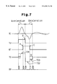
- FIG. 7 is a timing chart illustrating a single track jump control operation performed by the track jump control circuit of FIG. 4 .
- FIG. 4 is a schematic block diagram showing a track jump control circuit 100 according to the present invention.
- the track jump control circuit 100 is incorporated in the servo controller 6 of FIG. 1 .
- the track jump control circuit 100 includes a two one-shot pulse generating circuits 7 , 8 and XOR gate 12 , a counter 9 , a track counter 11 , and a control circuit 10 .
- the first one-shot pulse generating circuit 7 does not output a signal for a certain period when an input signal is maintained in a low state or a high state and generates a pulse signal at the point when the input signal changes.
- the first one-shot pulse generating circuit 7 receives the track jump signal TJ and outputs pulse signals D 1 , D 3 , . . . when the level of the track jump signal TJ changes.
- the second one-shot pulse generating circuit 8 receives the off track signal OT and outputs pulse signals P 2 , P 4 , . . . when the level of the off track signal OT changes.
- the pulse signals P 1 , P 3 . . . and P 2 , P 4 , . . . are synthesized by the XOR gate 12 and output from the XOR gate 12 as a latch pulse signal RP.
- the latch pulse signal RP is generated when the level of either the track jump signal TJ or the off track signal OT changes.
- An OR gate may be used in lieu of the XOR gate 12 .
- the track jump signal TJ rises or falls when the center of the pickup 3 is located at the center of the recording track.
- the off track signal OT rises or falls when the center of the pickup 3 is located at an edge of the track.
- the phase difference between the off track signal OT and the track jump signal TJ is ⁇ 90°. Accordingly, a single cycle of the track jump signal TJ or the off track signal OT may be divided into four sections at the following four timings.
- the latch pulse signal RP is generated four times whenever the pickup 3 moves across a track.
- the counter 9 counts the pulses of the clock signal CLK, which has a predetermined cycle that is sufficiently earlier than the latch pulse signal RP, in response to the input of the latch pulse signal RP until the next latch pulse signal RP is input.
- the counter 9 then sends the count value to the control circuit 10 .
- the control circuit 10 outputs the drive signal TD to the actuator 4 to perform the track jump.
- the control circuit 10 When the track jump is started, the control circuit 10 outputs a drive signal TD 1 , which has a predetermined level, for a constant time t1 (see FIG. 6 ).
- the control circuit 10 maintains the drive signal TD 1 until receiving the latch pulse signal RP preferably, one or twice. Afterward, the control circuit 10 maintains the drive signal TD at a null level until receiving the next new latch pulse signal RP.
- the control circuit 10 Upon the receipt of the next pulse signal RP, the control circuit 10 outputs a drive signal TD in accordance with the count value from the counter 9 .
- the count value of the counter 9 is compared with a predetermined value.
- the predetermined value is a count value determined in correspondence with the optimal moving speed of the pickup 3 .
- the adjustment of the drive signal TD controls the actuator 4 and moves the pickup 3 at an optimal speed.
- the track counter 11 receives the track jump signal TJ (or the off track signal OT), counts the received signal, and outputs a count signal the represents the number of tracks on which track jump was carried out.
- the track counter 11 sends a count signal to the control circuit 10 .
- the count signal is output when a track located one track before the target track is counted.
- the control circuit 10 receives the count signal from the track counter 11 and outputs a drive signal TD to decelerate the pickup 3 .
- FIG. 6 shows the track jump signal TJ, the off track signal OT, the latch pulse signal RP, and the drive signal TD.
- the pickup 3 Prior to the initiation point “Start”, the pickup 3 is located above a track.
- the track jump signal TJ and the off track signal OT are thus both low. Since the track jump signal TJ may be unstable immediately after starting acceleration, the drive signal TD (TD 1 ), which has a constant level, is output for a constant time t1 so that acceleration occurs at a constant rate.
- the pickup 3 moves a certain distance, the pickup 3 is separated from the center of the track, causing the track jump signal TJ to go high. Acceleration at a constant rate is continued even after the constant time t1 elapses.
- the drive signal TD (TD 2 ) temporarily goes null and stops the acceleration. The acceleration may also be stopped when the off track signal OT goes high (i.e., when the latch pulse signal P 2 is detected).
- the movement of the pickup 3 is maintained at a constant speed.
- the moving speed is computed by measuring the time from when the latch pulse signal P 3 is detected to when the off track signal OT goes low, or when the latch pulse signal P 4 is detected. If the moving speed is equal to or lower than the target speed (i.e., if the count value is equal to or greater than a predetermined value), the drive signal (TD 3 ) corresponding to the measured value is output and the acceleration is continued until the next latch pulse signal P 5 is received.
- a drive signal (TD 4 ) having the opposite polarity (in this case, negative polarity) is output to decelerate the pickup 3 .
- the drive signal TD for the period until the next latch pulse signal is received is adjusted in accordance with the count values of the latch pulse signals P 4 and P 5 .
- the speed during the period between the current latch pulse signal RP and one latch pulse signal RP prior to the current latch pulse signal RP is computed every time the latch pulse signal RP is received.
- the drive signal TD corresponding to the computation result is output until the next latch pulse signal RP is received.
- the adjustment of the drive signal TD controls the speed of the pickup 3 at a time resolution of one fourth of a cycle of the track jump signal TJ or the off track signal OT.
- a negative drive signal TD is output and deceleration is performed at a constant rate.
- the off track signal goes low (i.e., when the pickup 3 is arranged above the track)
- the time from when the track jump signal TJ goes low to when the off track OT goes low is measured. If the deceleration relative to the measured time is sufficient, the drive signal TD is corrected so that the absolute value of the drive signal TD decreases. If the deceleration is insufficient, the drive signal TD is compensated so that the absolute value of the drive signal TD increases. In this manner, the pickup 3 is moved to the desired track.
- the speed of the pickup 3 is controlled by dividing the period during which the pickup 3 moves over one track into four parts. Accordingly, the speed of the pickup 3 is finely controlled. This prevents the pickup 3 from overrunning the predetermined track, or sliding. Accordingly, movement between songs on a CD and access of data on a CD-ROM takes place more quickly and accurately.
- FIG. 7 shows the tracking error signal TE, the track jump signal TJ, the off track signal OT, the drive signal TD, and the latch pulse signal RP.
- the pickup 3 When acceleration is started (the left side of the drawing), the pickup 3 is located above a track and the off track signal OT is low. Further, the tracking error signal TE is substantially null. Thus, the track jump signal TJ is low.
- the control circuit 100 outputs a drive signal TD 1 having a predetermined level in response to a track jump initiation signal TRG from an external apparatus and accelerates the pickup 3 .
- the tracking error signal TE is near a null level and the output of the drive signal TD 1 is continued for a constant time t1 just in case the track jump signal TJ is unstable. After the pickup 3 has moved a certain distance, the pickup 3 is separated from the center of the track.
- the tracking error signal TE takes either a positive or negative value and the track jump signal TJ becomes either high or low.
- the off track signal OT goes high at a first changing point A.
- the track jump signal TJ goes low at a second changing point B. The acceleration process is continued and the drive signal TD 1 is maintained at a high level until point B.
- the control circuit 10 proceeds to the deceleration process in response to the latch pulse signal RP that is output at the second change point B where the track jump signal TJ falls. Further, in response to the latch pulse signal RP output at the second changing point B, the counter 9 starts the counting operation. The control circuit 10 inverts the polarity of the drive signal TD (in this case, to the negative polarity) and outputs a deceleration drive signal TD 2 . When the main reading beam P moves onto the next track, the off track signal OT goes low at a third changing point C.
- the latch pulse signal RP is output at the third changing point C, and the counter 9 sends the count value in response to that latch pulse signal RP to reset the counter value.
- the control circuit 10 determines that the deceleration of the pickup 3 is sufficient if the count value exceeds a predetermined value and determines that the deceleration is insufficient if the count value is less than the predetermined value. If the deceleration is insufficient, the control circuit 10 outputs a drive signal TD 3 corresponding to the difference between the predetermined value and the count value and decelerates the pickup 3 accordingly.
- a predetermined time t2 elapses from the third changing point C, the deceleration process is finished. This causes the drive signal TD to go null and servo controls the pickup 3 along the track. In this manner, the pickup 3 is moved from one track to an adjacent track.
- the deceleration status is monitored at the third changing point C.
- the monitored status is fed back to the deceleration process in order to prevent the pickup 3 from stopping before reaching the target position due to sliding or an excessive deceleration force.
Landscapes
- Moving Of The Head For Recording And Reproducing By Optical Means (AREA)
- Moving Of Head For Track Selection And Changing (AREA)
Abstract
Description
Claims (6)
Applications Claiming Priority (4)
| Application Number | Priority Date | Filing Date | Title |
|---|---|---|---|
| JP10337853A JP2000163762A (en) | 1998-11-27 | 1998-11-27 | Method and circuit for track jump control |
| JP10-337853 | 1998-11-27 | ||
| JP10-340496 | 1998-11-30 | ||
| JP10340496A JP2000163764A (en) | 1998-11-30 | 1998-11-30 | Track jump control method and track jump control circuit |
Publications (1)
| Publication Number | Publication Date |
|---|---|
| US6501714B1 true US6501714B1 (en) | 2002-12-31 |
Family
ID=26575932
Family Applications (1)
| Application Number | Title | Priority Date | Filing Date |
|---|---|---|---|
| US09/444,924 Expired - Lifetime US6501714B1 (en) | 1998-11-27 | 1999-11-24 | Method and apparatus for controlling track jump |
Country Status (2)
| Country | Link |
|---|---|
| US (1) | US6501714B1 (en) |
| KR (1) | KR20000035707A (en) |
Cited By (2)
| Publication number | Priority date | Publication date | Assignee | Title |
|---|---|---|---|---|
| US6621773B2 (en) * | 2000-03-08 | 2003-09-16 | Via Technologies, Inc. | Glitch protection method in optical storage device |
| US20130235713A1 (en) * | 2012-03-06 | 2013-09-12 | Sony Corporation | Optical recording medium driving apparatus and cross track signal generation method |
Citations (2)
| Publication number | Priority date | Publication date | Assignee | Title |
|---|---|---|---|---|
| US5428590A (en) * | 1991-06-04 | 1995-06-27 | Canon Kabushiki Kaisha | Information recording and reproducing apparatus and method in which an information recording or reproducing head seeks a desired track on a recording medium |
| US6314066B1 (en) * | 1999-07-21 | 2001-11-06 | Lg Electronics Inc. | Method for controlling track jump in optical recording medium |
-
1999
- 1999-11-24 US US09/444,924 patent/US6501714B1/en not_active Expired - Lifetime
- 1999-11-26 KR KR1019990052870A patent/KR20000035707A/en not_active Ceased
Patent Citations (2)
| Publication number | Priority date | Publication date | Assignee | Title |
|---|---|---|---|---|
| US5428590A (en) * | 1991-06-04 | 1995-06-27 | Canon Kabushiki Kaisha | Information recording and reproducing apparatus and method in which an information recording or reproducing head seeks a desired track on a recording medium |
| US6314066B1 (en) * | 1999-07-21 | 2001-11-06 | Lg Electronics Inc. | Method for controlling track jump in optical recording medium |
Cited By (2)
| Publication number | Priority date | Publication date | Assignee | Title |
|---|---|---|---|---|
| US6621773B2 (en) * | 2000-03-08 | 2003-09-16 | Via Technologies, Inc. | Glitch protection method in optical storage device |
| US20130235713A1 (en) * | 2012-03-06 | 2013-09-12 | Sony Corporation | Optical recording medium driving apparatus and cross track signal generation method |
Also Published As
| Publication number | Publication date |
|---|---|
| KR20000035707A (en) | 2000-06-26 |
Similar Documents
| Publication | Publication Date | Title |
|---|---|---|
| US5844871A (en) | Optical disk track counting apparatus and method for improved track access | |
| JP2845230B2 (en) | Beam spot speed detector for optical disk drive | |
| US4955009A (en) | Optical disk drive apparatus having counter disable at seek start-up | |
| EP0289309B1 (en) | An apparatus for reading an optical disk | |
| US5548569A (en) | Tracking traverse control circuit for head unit of disc player | |
| JPH06236563A (en) | Optical disc high speed search control device and method | |
| US5307333A (en) | Track servo pull-in method and apparatus for an optical disc | |
| JP3455298B2 (en) | Optical beam movement detection method and optical disk reproducing apparatus | |
| US4541083A (en) | For jumping a light spot on a track of a recording medium | |
| US6233207B1 (en) | Polarity switching signal generator, method of the same, and optical disk drive | |
| US6501714B1 (en) | Method and apparatus for controlling track jump | |
| JPH02232874A (en) | Track retrieving device | |
| US6351437B1 (en) | Tracking servo circuit | |
| US5600626A (en) | Optical disk of sampled servo type having synchronization a marks for simple synchronization detection | |
| US5216651A (en) | Pickup-drive stabilizing apparatus for an optical disc player | |
| EP0818777B1 (en) | Optical seeking method and apparatus | |
| JP3067529B2 (en) | Optical disk drive | |
| US5210731A (en) | Information processing apparatus with missing pulse detection and correction | |
| JPH0775078B2 (en) | Optical disk device | |
| KR100224834B1 (en) | Apparatus and Method of Profile of Sled Search Speed | |
| JP2773132B2 (en) | Tracking control device | |
| JP2576422B2 (en) | Optical disk information reproducing device | |
| JPH0261867A (en) | Access controlling system | |
| JP2000339709A (en) | Optical disk recording and playback device | |
| KR100200584B1 (en) | How to brake slad motor on compact disc drive |
Legal Events
| Date | Code | Title | Description |
|---|---|---|---|
| AS | Assignment |
Owner name: SANYO ELECTRIC CO., LTD., JAPAN Free format text: ASSIGNMENT OF ASSIGNORS INTEREST;ASSIGNORS:TAKANO, KOJI;KAJITANI, YUJI;REEL/FRAME:010432/0600 Effective date: 19991122 |
|
| STCF | Information on status: patent grant |
Free format text: PATENTED CASE |
|
| FEPP | Fee payment procedure |
Free format text: PAYOR NUMBER ASSIGNED (ORIGINAL EVENT CODE: ASPN); ENTITY STATUS OF PATENT OWNER: LARGE ENTITY |
|
| FPAY | Fee payment |
Year of fee payment: 4 |
|
| FPAY | Fee payment |
Year of fee payment: 8 |
|
| FEPP | Fee payment procedure |
Free format text: PAYER NUMBER DE-ASSIGNED (ORIGINAL EVENT CODE: RMPN); ENTITY STATUS OF PATENT OWNER: LARGE ENTITY Free format text: PAYOR NUMBER ASSIGNED (ORIGINAL EVENT CODE: ASPN); ENTITY STATUS OF PATENT OWNER: LARGE ENTITY |
|
| AS | Assignment |
Owner name: SEMICONDUCTOR COMPONENTS INDUSTRIES, LLC, ARIZONA Free format text: ASSIGNMENT OF ASSIGNORS INTEREST;ASSIGNOR:SANYO ELECTRIC CO., LTD.;REEL/FRAME:026594/0385 Effective date: 20110101 |
|
| AS | Assignment |
Owner name: SEMICONDUCTOR COMPONENTS INDUSTRIES, LLC, ARIZONA Free format text: CORRECTIVE ASSIGNMENT TO CORRECT THE INCORRECT #12/577882 PREVIOUSLY RECORDED ON REEL 026594 FRAME 0385. ASSIGNOR(S) HEREBY CONFIRMS THE ASSIGNMENT;ASSIGNOR:SANYO ELECTRIC CO., LTD;REEL/FRAME:032836/0342 Effective date: 20110101 |
|
| FPAY | Fee payment |
Year of fee payment: 12 |
|
| AS | Assignment |
Owner name: DEUTSCHE BANK AG NEW YORK BRANCH, NEW YORK Free format text: SECURITY INTEREST;ASSIGNOR:SEMICONDUCTOR COMPONENTS INDUSTRIES, LLC;REEL/FRAME:038620/0087 Effective date: 20160415 |
|
| AS | Assignment |
Owner name: DEUTSCHE BANK AG NEW YORK BRANCH, AS COLLATERAL AG Free format text: CORRECTIVE ASSIGNMENT TO CORRECT THE INCORRECT PATENT NUMBER 5859768 AND TO RECITE COLLATERAL AGENT ROLE OF RECEIVING PARTY IN THE SECURITY INTEREST PREVIOUSLY RECORDED ON REEL 038620 FRAME 0087. ASSIGNOR(S) HEREBY CONFIRMS THE SECURITY INTEREST;ASSIGNOR:SEMICONDUCTOR COMPONENTS INDUSTRIES, LLC;REEL/FRAME:039853/0001 Effective date: 20160415 Owner name: DEUTSCHE BANK AG NEW YORK BRANCH, AS COLLATERAL AGENT, NEW YORK Free format text: CORRECTIVE ASSIGNMENT TO CORRECT THE INCORRECT PATENT NUMBER 5859768 AND TO RECITE COLLATERAL AGENT ROLE OF RECEIVING PARTY IN THE SECURITY INTEREST PREVIOUSLY RECORDED ON REEL 038620 FRAME 0087. ASSIGNOR(S) HEREBY CONFIRMS THE SECURITY INTEREST;ASSIGNOR:SEMICONDUCTOR COMPONENTS INDUSTRIES, LLC;REEL/FRAME:039853/0001 Effective date: 20160415 |
|
| AS | Assignment |
Owner name: FAIRCHILD SEMICONDUCTOR CORPORATION, ARIZONA Free format text: RELEASE OF SECURITY INTEREST IN PATENTS RECORDED AT REEL 038620, FRAME 0087;ASSIGNOR:DEUTSCHE BANK AG NEW YORK BRANCH, AS COLLATERAL AGENT;REEL/FRAME:064070/0001 Effective date: 20230622 Owner name: SEMICONDUCTOR COMPONENTS INDUSTRIES, LLC, ARIZONA Free format text: RELEASE OF SECURITY INTEREST IN PATENTS RECORDED AT REEL 038620, FRAME 0087;ASSIGNOR:DEUTSCHE BANK AG NEW YORK BRANCH, AS COLLATERAL AGENT;REEL/FRAME:064070/0001 Effective date: 20230622 |