US6500024B2 - Circuit protection mechanism for CPU socket - Google Patents

Circuit protection mechanism for CPU socket Download PDF

Info

Publication number
US6500024B2
US6500024B2 US09/991,698 US99169801A US6500024B2 US 6500024 B2 US6500024 B2 US 6500024B2 US 99169801 A US99169801 A US 99169801A US 6500024 B2 US6500024 B2 US 6500024B2
Authority
US
United States
Prior art keywords
heat sink
cpu
cpu socket
socket
main body
Prior art date
Legal status (The legal status is an assumption and is not a legal conclusion. Google has not performed a legal analysis and makes no representation as to the accuracy of the status listed.)
Expired - Lifetime
Application number
US09/991,698
Other versions
US20020067600A1 (en
Inventor
Hsien-Yueh Hsu
Current Assignee (The listed assignees may be inaccurate. Google has not performed a legal analysis and makes no representation or warranty as to the accuracy of the list.)
Asustek Computer Inc
Original Assignee
Asustek Computer Inc
Priority date (The priority date is an assumption and is not a legal conclusion. Google has not performed a legal analysis and makes no representation as to the accuracy of the date listed.)
Filing date
Publication date
Application filed by Asustek Computer Inc filed Critical Asustek Computer Inc
Assigned to ASUSTEK COMPUTER INC. reassignment ASUSTEK COMPUTER INC. ASSIGNMENT OF ASSIGNORS INTEREST (SEE DOCUMENT FOR DETAILS). Assignors: HSU, HSIEN-YUEH
Publication of US20020067600A1 publication Critical patent/US20020067600A1/en
Application granted granted Critical
Publication of US6500024B2 publication Critical patent/US6500024B2/en
Anticipated expiration legal-status Critical
Expired - Lifetime legal-status Critical Current

Links

Images

Classifications

    • HELECTRICITY
    • H01ELECTRIC ELEMENTS
    • H01LSEMICONDUCTOR DEVICES NOT COVERED BY CLASS H10
    • H01L23/00Details of semiconductor or other solid state devices
    • H01L23/34Arrangements for cooling, heating, ventilating or temperature compensation ; Temperature sensing arrangements
    • H01L23/40Mountings or securing means for detachable cooling or heating arrangements ; fixed by friction, plugs or springs
    • H01L23/4093Snap-on arrangements, e.g. clips
    • HELECTRICITY
    • H01ELECTRIC ELEMENTS
    • H01LSEMICONDUCTOR DEVICES NOT COVERED BY CLASS H10
    • H01L2924/00Indexing scheme for arrangements or methods for connecting or disconnecting semiconductor or solid-state bodies as covered by H01L24/00
    • H01L2924/0001Technical content checked by a classifier
    • H01L2924/0002Not covered by any one of groups H01L24/00, H01L24/00 and H01L2224/00

Landscapes

  • Physics & Mathematics (AREA)
  • Condensed Matter Physics & Semiconductors (AREA)
  • General Physics & Mathematics (AREA)
  • Engineering & Computer Science (AREA)
  • Computer Hardware Design (AREA)
  • Microelectronics & Electronic Packaging (AREA)
  • Power Engineering (AREA)
  • Cooling Or The Like Of Electrical Apparatus (AREA)
  • Cooling Or The Like Of Semiconductors Or Solid State Devices (AREA)

Abstract

A Central Processing Unit (CPU) socket having a circuit protection mechanism electrically couples a CPU to a Printed Circuit Board (PCB). The heat sink fastener matches the supports positioned on two opposing sides of the main body for mounting the heat sink on the CPU socket tightly. The protection component protrudes the main body and covers the corresponding PCB trace under the supports to protect the PCB trace from damaged by the heat sink fastener as mounting or dismounting the heat sink on the CPU socket.

Description

This application incorporates by reference Taiwanese application Serial No. 89126032, Filed Dec. 6, 2000.
BACKGROUND OF THE INVENTION
1. Field of the Invention
The invention relates in general to a circuit protection mechanism, and more particularly to a circuit protection mechanism for CPU socket.
2. Description of the Related Art
Referring to FIG. 1, the traditional CPU socket on the motherboard is illustrated. The CPU socket 102 is for placing a Central Processing Unit (CPU). The CPU socket 102 electrically couples the CPU to the Printed Circuit Board (PCB). The layout of the PCB 106 arranges the PCB trace 108 around the CPU socket 102.
The speedier processing and better performance of the CPU requires higher frequency as well as higher voltage and therefore generates lots of heat. The high temperature would decrease the life span of the CPU and easily cause the instability of the computer system. All modern CPUs require a heat sink to solve this problem. The heat sink is designed to lower the temperature of the CPU by dissipating heat into the surrounding air so that the CPU can run well. As shown in FIG. 1, The supports 104 positioned on two opposing sides of the CPU socket 102 matches the heat sink fastener for mounting the heat sink on the CPU socket 102.
In order to be more efficient, the surface area of the heat sink is designed to be as big as possible that good thermal transfer is possible inside the heat sink. Hence the heat sink made up of metal is big and heavy for a better thermal conductivity. It sometimes requires strenuous effort to mounting or dismounting the heat sink on the CPU socket. However, the fixing end of the heat sink fastener might damage the PCB trace 108 on the PCB 106 and the whole motherboard is beyond repair and has to be cast away. Especially for the computer DIY user, the failure rate of the computer system is up to 10% when it comes to upgrading the CPU. The troublesome matter is that the user usually can not figure out the crux of the problem until the last minute. However, the computer system has failed and the layout on the PCB has been damaged due to improper forcing as mounting or dismounting the heat sink on the CPU socket.
SUMMARY OF THE INVENTION
It is therefore an object of the invention to provide a CPU socket having a circuit protection mechanism. The circuit of the Printed Circuit Board (PCB) is covered by the protection component. The fixing end of the heat sink fastener cannot directly touch the PCB to damage the PCB trace on the PCB as mounting or dismounting the heat sink on the CPU socket.
The invention achieves the above-identified objects by providing a Central Processing Unit (CPU) socket having a circuit protection mechanism. The CPU socket electrically couples a CPU to a Printed Circuit Board (PCB). The heat sink fastener matches the supports positioned on two opposing sides of the main body for mounting the heat sink on the CPU socket tightly. The protection component protrudes the main body and covers the corresponding PCB trace under the supports to protect the PCB trace from damaged by the heat sink fastener as mounting or dismounting the heat sink on the CPU socket. The protection component can be formed on the main body and made up of several sheets placed under the supports individually or a single sheet placed under the supports. The protection component can also be a detachable mechanism for holding and positioned around the periphery of the main body.
BRIEF DESCRIPTION OF THE DRAWINGS
Other objects, features, and advantages of the invention will become apparent from the following detailed description of the preferred but non-limiting embodiments. The description is made with reference to the accompanying drawings in which:
FIG. 1 (Prior Art) illustrates the traditional CPU socket on the motherboard;
FIG. 2A shows a perspective view of a CPU socket having a circuit protection mechanism according to one preferred embodiment of the invention as well as the heat sink;
FIG. 2B shows a perspective view of a CPU socket having a circuit protection mechanism according to another preferred embodiment of the invention as well as the heat sink;
FIG. 2C shows a perspective view of a CPU socket having a circuit protection mechanism according to the other preferred embodiment of the invention as well as the heat sink;
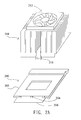
FIG. 3 shows a side, cross-sectional view of a CPU socket having a circuit protection mechanism according to the preferred embodiment of the invention, in which the heat sink is mounted on the CPU socket; and
FIGS. 44C shows a side view of heat sink fasteners of the embodiments of the invention.
DESCRIPTION OF THE PREFERRED EMBODIMENT
Referring first to FIGS. 2A to 2C, perspective views of the CPU socket having a circuit protection mechanism according to the preferred embodiments of the invention as well as the heat sink are shown. The heat sink fastener 210 matches the supports 204 positioned on two opposing sides of the main body 202 for mounting the heat sink 208 on the CPU socket 200 tightly. The fan 212 connects to the top of the heat sink 208. The heat generated by the CPU 214 (as shown in FIG. 3) can be conducted from the lower part of the heat sink 208, that is in contact with the CPU 214, to the fins and then dissipated into the surrounding air by the fan 212. Besides, the protection component 206 protrudes the main body 202 to cover the corresponding PCB trace 108 under the supports 204 which match the heat sink fastener. It avoids damaging the PCB trace 108 by the fixing end of the heat sink fastener 210 as mounting or dismounting the heat sink 208 on the CPU socket 200. The protection component 206 can be either formed on the main body 202 or an additional mechanism connected to the main body 202 in accordance with the molds. There are various types of the protection component 206. As shown in FIG. 2B, the protection component 206 is made up of several sheets placed under the supports 204 individually. As shown in FIG. 2A, the protection component 206 is made up of a single sheet placed under the supports 204. Moreover, the protection component 206 can also be a detachable mechanism for holding and positioned around the periphery of the main body 202. The detachable mechanism includes at least a sheet placed under the supports 204.
Referring to FIG. 3, a side, cross-sectional view of a CPU socket having a circuit protection mechanism according to the preferred embodiment of the invention, in which the heat sink is mounted on the CPU socket is shown. As shown in FIG. 3, the heat sink fastener 210 bestrides the heat sink 208 and presses the heat sink 208 onto the CPU socket 200 from both sides. The first fixing end 210 a of the heat sink fastener 210 clips the support 204 a on one side of the main body 202 while the second fixing end 210 b of the heat sink fastener 210 clips the supports 204 b on the other side of the main body 202. Since the first protection component 206 a and the second protection component 206 b respectively connect to the opposing sides of the main body 202 and cover the corresponding PCB trace 108 under the supports 204 which match the heat sink fastener 210. It avoids damaging the PCB trace 108 when mounting or dismounting the heat sink 208 on the CPU socket 200. Even the user inadvertently presses down on the PCB, the first fixing end 210 a or the second fixing end 210 b of the heat sink fastener 210 can not touch and damage the PCB trace 108.
Referring to FIGS. 4A to 4C, a side view of heat sink fasteners of the embodiments of the invention is shown. In order to prevent the PCB trace 108 from damaged due to the directly touching of the first fixing end 210 a or the second fixing end 210 b of the heat sink fastener 210, the heat sink faster 210 itself can be designed to be smoother and duller. For example, the first fixing end 210 a and the second fixing end 210 b, which might touch the PCB, are turned rounded in FIG. 4A, flat in FIG. 4B or hooked in FIG. 4C.
However, the standards of the heat sink and ways to fix the heat sink on the CPU socket differ from each heat sink manufacturer. As for a motherboard manufacturer, the protruding protection component connected to the CPU socket can be designed to be an extension structure of the CPU socket and made by the same material. The protruding protection component can also be simply placed on the bottom of the CPU socket or positioned around the periphery of the main body in a detachable design.
The CPU socket having a circuit protection mechanism according to the invention efficiently decreases the failure rate of the computer system due to improper forcing as mounting or dismounting the heat sink on the CPU socket. The fixing end of the heat sink fastener can not touch and damage the PCB trace even the user inadvertently presses down on the PCB. It avoids damaging the layout of the PCB and improve the reliability and stability of the motherboard.
While the invention has been described by way of example and in terms of the preferred embodiment, it is to be understood that the invention is not limited to the disclosed embodiment. To the contrary, it is intended to cover various modifications and similar arrangements and procedures, and the scope of the appended claims therefore should be accorded the broadest interpretation so as to encompass all such modifications and similar arrangements and procedures.

Claims (7)

What is claimed is:
1. A Central Processing Unit (CPU) socket having a circuit protection mechanism capable of electrically coupling a CPU to a Printed Circuit Board (PCB) and mounting a heat sink by a heat sink fastener; the CPU socket comprising:
a main body for connecting the CPU;
a plurality of supports positioned on two opposing sides of the main body and matching the heat sink fastener for mounting the heat sink on the CPU socket; and
a protection component protruding the main body and covering at least the corresponding PCB trace under the supports which match the heat sink fastener to protect the PCB trace from damaged by the heat sink fastener as mounting or dismounting the heat sink on the CPU socket.
2. The CPU socket having a circuit protection mechanism according to claim 1, wherein the protection component is made up of a plurality of sheets placed under the supports individually.
3. The CPU socket having a circuit protection mechanism according to claim 1, wherein the protection component is made up of a single sheet placed under the supports.
4. The CPU socket having a circuit protection mechanism according to claim 1, wherein the protection component is formed on the main body.
5. The CPU socket having a circuit protection mechanism according to claim 1, wherein the protection component is a detachable mechanism for holding.
6. The CPU socket having a circuit protection mechanism according to claim 5, wherein the detachable mechanism for holding is positioned around the periphery of the main body.
7. The CPU socket having a circuit protection mechanism according to claim 6, wherein the detachable mechanism for holding comprises at least a sheet placed under the supports.
US09/991,698 2000-12-06 2001-11-26 Circuit protection mechanism for CPU socket Expired - Lifetime US6500024B2 (en)

Applications Claiming Priority (3)

Application Number Priority Date Filing Date Title
TW89126032 2000-12-06
TW89126032A 2000-12-06

Publications (2)

Publication Number Publication Date
US20020067600A1 US20020067600A1 (en) 2002-06-06
US6500024B2 true US6500024B2 (en) 2002-12-31

Family

ID=21662218

Family Applications (1)

Application Number Title Priority Date Filing Date
US09/991,698 Expired - Lifetime US6500024B2 (en) 2000-12-06 2001-11-26 Circuit protection mechanism for CPU socket

Country Status (1)

Country Link
US (1) US6500024B2 (en)

Cited By (3)

* Cited by examiner, † Cited by third party
Publication number Priority date Publication date Assignee Title
US6994584B1 (en) * 2002-08-30 2006-02-07 Advanced Micro Devices, Inc. Thermally conductive integrated circuit mounting structures
US20060268512A1 (en) * 2005-05-25 2006-11-30 International Business Machines Corporation Slave mode thermal control with throttling and shutdown
US20140321064A1 (en) * 2011-11-21 2014-10-30 Thomson Licensing Hold down for retaining a heat sink

Families Citing this family (1)

* Cited by examiner, † Cited by third party
Publication number Priority date Publication date Assignee Title
US20140187058A1 (en) * 2012-12-27 2014-07-03 Hongfei Yan Modular Multiple Piece Socket For Enhanced Thermal Management

Citations (9)

* Cited by examiner, † Cited by third party
Publication number Priority date Publication date Assignee Title
US5241453A (en) * 1991-11-18 1993-08-31 The Whitaker Corporation EMI shielding device
US5282111A (en) * 1989-06-09 1994-01-25 Labinal Components And Systems, Inc. Thermal transfer plate and integrated circuit chip or other electrical component assemblies including such plate
US5302853A (en) * 1993-01-25 1994-04-12 The Whitaker Corporation Land grid array package
US5602719A (en) * 1995-11-13 1997-02-11 Intel Corporation No handle zip socket
US6071128A (en) * 1998-04-28 2000-06-06 International Business Machines Corporation Integrated circuit socket with built in EMC grounding for a heat sink
US6226185B1 (en) * 1999-11-26 2001-05-01 Asia Vital Components Co., Ltd. Heat sink having anti-electromagnetic wave device
US6295203B1 (en) * 2000-04-05 2001-09-25 Foxconn Precision Components Co., Ltd. Heat sink clip assembly
US6301112B1 (en) * 1999-12-23 2001-10-09 Foxconn Precision Components Co., Ltd. Clip mounting a heat sink to an electronic element
US6442026B2 (en) * 1999-12-13 2002-08-27 Kabushiki Kaisha Toshiba Apparatus for cooling a circuit component

Patent Citations (9)

* Cited by examiner, † Cited by third party
Publication number Priority date Publication date Assignee Title
US5282111A (en) * 1989-06-09 1994-01-25 Labinal Components And Systems, Inc. Thermal transfer plate and integrated circuit chip or other electrical component assemblies including such plate
US5241453A (en) * 1991-11-18 1993-08-31 The Whitaker Corporation EMI shielding device
US5302853A (en) * 1993-01-25 1994-04-12 The Whitaker Corporation Land grid array package
US5602719A (en) * 1995-11-13 1997-02-11 Intel Corporation No handle zip socket
US6071128A (en) * 1998-04-28 2000-06-06 International Business Machines Corporation Integrated circuit socket with built in EMC grounding for a heat sink
US6226185B1 (en) * 1999-11-26 2001-05-01 Asia Vital Components Co., Ltd. Heat sink having anti-electromagnetic wave device
US6442026B2 (en) * 1999-12-13 2002-08-27 Kabushiki Kaisha Toshiba Apparatus for cooling a circuit component
US6301112B1 (en) * 1999-12-23 2001-10-09 Foxconn Precision Components Co., Ltd. Clip mounting a heat sink to an electronic element
US6295203B1 (en) * 2000-04-05 2001-09-25 Foxconn Precision Components Co., Ltd. Heat sink clip assembly

Cited By (10)

* Cited by examiner, † Cited by third party
Publication number Priority date Publication date Assignee Title
US6994584B1 (en) * 2002-08-30 2006-02-07 Advanced Micro Devices, Inc. Thermally conductive integrated circuit mounting structures
US7272010B1 (en) 2002-08-30 2007-09-18 Advanced Micro Devices, Inc. Thermally conductive integrated circuit mounting structures
US20060268512A1 (en) * 2005-05-25 2006-11-30 International Business Machines Corporation Slave mode thermal control with throttling and shutdown
US20080137247A1 (en) * 2005-05-25 2008-06-12 Ibm Corporation Slave Mode Thermal Control with Throttling and Shutdown
US20080137256A1 (en) * 2005-05-25 2008-06-12 Ibm Corporation Slave Mode Thermal Control with Throttling and Shutdown
US7394636B2 (en) 2005-05-25 2008-07-01 International Business Machines Corporation Slave mode thermal control with throttling and shutdown
US7539000B2 (en) 2005-05-25 2009-05-26 International Business Machines Corporation Slave mode thermal control with throttling and shutdown
US7545617B2 (en) 2005-05-25 2009-06-09 International Business Machines Corporation Slave mode thermal control with throttling and shutdown
US20140321064A1 (en) * 2011-11-21 2014-10-30 Thomson Licensing Hold down for retaining a heat sink
US9907208B2 (en) * 2011-11-21 2018-02-27 Thomson Licensing Hold down for retaining a heat sink

Also Published As

Publication number Publication date
US20020067600A1 (en) 2002-06-06

Similar Documents

Publication Publication Date Title
US6153932A (en) Fix base of integrated circuit chipset and heat sink
US7382621B2 (en) Video graphics array (VGA) card assembly
US7133284B2 (en) Power supply without cooling fan
US6717814B2 (en) Heat dissipation assembly
US20030159819A1 (en) Heatsink device for cooling chipset
US6415853B1 (en) Wind cover locking element structure of heat radiator
US6822869B2 (en) Fastening device
US20070263360A1 (en) Memory module assembly including a clip for mounting a heat sink thereon
US7336496B1 (en) Fixing structure for computer mainboard
US8070124B2 (en) Supporting stand with heat dissipation device
KR100464990B1 (en) Circuit board support
US20040250993A1 (en) Heat-dissipating device
CN101414206A (en) Heat radiating device of memory
US20080083528A1 (en) Heat dissipation device having mounting brackets
US7487825B2 (en) Heat dissipation device
US6434004B1 (en) Heat sink assembly
US7495923B2 (en) Heat dissipation device having fixing bracket
US20070165380A1 (en) Memory module assembly including a clip for mounting a heat sink thereon
US20070025086A1 (en) Electronic device with sliding type heatsink
US6560113B1 (en) Electronic device assembly having thermal module for heat dissipation
US7085136B2 (en) Heat duct-equipped heat-radiating device for power supply
US7042719B2 (en) Electronic device and module structure thereof
US6500024B2 (en) Circuit protection mechanism for CPU socket
US20060023423A1 (en) Expandable heat sink
US7363964B2 (en) Heat sink

Legal Events

Date Code Title Description
AS Assignment

Owner name: ASUSTEK COMPUTER INC., TAIWAN

Free format text: ASSIGNMENT OF ASSIGNORS INTEREST;ASSIGNOR:HSU, HSIEN-YUEH;REEL/FRAME:012324/0404

Effective date: 20011107

REMI Maintenance fee reminder mailed
FEPP Fee payment procedure

Free format text: PETITION RELATED TO MAINTENANCE FEES FILED (ORIGINAL EVENT CODE: PMFP); ENTITY STATUS OF PATENT OWNER: LARGE ENTITY

REIN Reinstatement after maintenance fee payment confirmed
FP Lapsed due to failure to pay maintenance fee

Effective date: 20061231

FPAY Fee payment

Year of fee payment: 4

SULP Surcharge for late payment
FEPP Fee payment procedure

Free format text: PETITION RELATED TO MAINTENANCE FEES GRANTED (ORIGINAL EVENT CODE: PMFG); ENTITY STATUS OF PATENT OWNER: LARGE ENTITY

PRDP Patent reinstated due to the acceptance of a late maintenance fee

Effective date: 20080108

STCF Information on status: patent grant

Free format text: PATENTED CASE

FPAY Fee payment

Year of fee payment: 8

FPAY Fee payment

Year of fee payment: 12