US6497394B1 - Cup anchor - Google Patents
Cup anchor Download PDFInfo
- Publication number
- US6497394B1 US6497394B1 US09/342,251 US34225199A US6497394B1 US 6497394 B1 US6497394 B1 US 6497394B1 US 34225199 A US34225199 A US 34225199A US 6497394 B1 US6497394 B1 US 6497394B1
- Authority
- US
- United States
- Prior art keywords
- anchor
- hole
- base
- cup
- screw
- Prior art date
- Legal status (The legal status is an assumption and is not a legal conclusion. Google has not performed a legal analysis and makes no representation as to the accuracy of the status listed.)
- Expired - Fee Related
Links
- 238000007373 indentation Methods 0.000 claims abstract description 24
- 125000006850 spacer group Chemical group 0.000 claims description 4
- 239000000463 material Substances 0.000 abstract description 12
- 235000013361 beverage Nutrition 0.000 description 30
- 238000004519 manufacturing process Methods 0.000 description 2
- 238000004026 adhesive bonding Methods 0.000 description 1
- 238000004873 anchoring Methods 0.000 description 1
- 238000010586 diagram Methods 0.000 description 1
- 239000002184 metal Substances 0.000 description 1
- 238000012986 modification Methods 0.000 description 1
- 230000004048 modification Effects 0.000 description 1
- 239000004033 plastic Substances 0.000 description 1
Images


Classifications
-
- A—HUMAN NECESSITIES
- A47—FURNITURE; DOMESTIC ARTICLES OR APPLIANCES; COFFEE MILLS; SPICE MILLS; SUCTION CLEANERS IN GENERAL
- A47G—HOUSEHOLD OR TABLE EQUIPMENT
- A47G23/00—Other table equipment
- A47G23/02—Glass or bottle holders
- A47G23/0208—Glass or bottle holders for drinking-glasses, plastic cups, or the like
- A47G23/0216—Glass or bottle holders for drinking-glasses, plastic cups, or the like for one glass or cup
- A47G23/0225—Glass or bottle holders for drinking-glasses, plastic cups, or the like for one glass or cup attachable to a plate, table, or the like
-
- F—MECHANICAL ENGINEERING; LIGHTING; HEATING; WEAPONS; BLASTING
- F16—ENGINEERING ELEMENTS AND UNITS; GENERAL MEASURES FOR PRODUCING AND MAINTAINING EFFECTIVE FUNCTIONING OF MACHINES OR INSTALLATIONS; THERMAL INSULATION IN GENERAL
- F16M—FRAMES, CASINGS OR BEDS OF ENGINES, MACHINES OR APPARATUS, NOT SPECIFIC TO ENGINES, MACHINES OR APPARATUS PROVIDED FOR ELSEWHERE; STANDS; SUPPORTS
- F16M11/00—Stands or trestles as supports for apparatus or articles placed thereon Stands for scientific apparatus such as gravitational force meters
- F16M11/02—Heads
- F16M11/04—Means for attachment of apparatus; Means allowing adjustment of the apparatus relatively to the stand
- F16M11/041—Allowing quick release of the apparatus
-
- F—MECHANICAL ENGINEERING; LIGHTING; HEATING; WEAPONS; BLASTING
- F16—ENGINEERING ELEMENTS AND UNITS; GENERAL MEASURES FOR PRODUCING AND MAINTAINING EFFECTIVE FUNCTIONING OF MACHINES OR INSTALLATIONS; THERMAL INSULATION IN GENERAL
- F16M—FRAMES, CASINGS OR BEDS OF ENGINES, MACHINES OR APPARATUS, NOT SPECIFIC TO ENGINES, MACHINES OR APPARATUS PROVIDED FOR ELSEWHERE; STANDS; SUPPORTS
- F16M11/00—Stands or trestles as supports for apparatus or articles placed thereon Stands for scientific apparatus such as gravitational force meters
- F16M11/20—Undercarriages with or without wheels
- F16M11/22—Undercarriages with or without wheels with approximately constant height, e.g. with constant length of column or of legs
-
- F—MECHANICAL ENGINEERING; LIGHTING; HEATING; WEAPONS; BLASTING
- F16—ENGINEERING ELEMENTS AND UNITS; GENERAL MEASURES FOR PRODUCING AND MAINTAINING EFFECTIVE FUNCTIONING OF MACHINES OR INSTALLATIONS; THERMAL INSULATION IN GENERAL
- F16M—FRAMES, CASINGS OR BEDS OF ENGINES, MACHINES OR APPARATUS, NOT SPECIFIC TO ENGINES, MACHINES OR APPARATUS PROVIDED FOR ELSEWHERE; STANDS; SUPPORTS
- F16M11/00—Stands or trestles as supports for apparatus or articles placed thereon Stands for scientific apparatus such as gravitational force meters
- F16M11/20—Undercarriages with or without wheels
- F16M11/24—Undercarriages with or without wheels changeable in height or length of legs, also for transport only, e.g. by means of tubes screwed into each other
- F16M11/38—Undercarriages with or without wheels changeable in height or length of legs, also for transport only, e.g. by means of tubes screwed into each other by folding, e.g. pivoting or scissors tong mechanisms
-
- F—MECHANICAL ENGINEERING; LIGHTING; HEATING; WEAPONS; BLASTING
- F16—ENGINEERING ELEMENTS AND UNITS; GENERAL MEASURES FOR PRODUCING AND MAINTAINING EFFECTIVE FUNCTIONING OF MACHINES OR INSTALLATIONS; THERMAL INSULATION IN GENERAL
- F16M—FRAMES, CASINGS OR BEDS OF ENGINES, MACHINES OR APPARATUS, NOT SPECIFIC TO ENGINES, MACHINES OR APPARATUS PROVIDED FOR ELSEWHERE; STANDS; SUPPORTS
- F16M13/00—Other supports for positioning apparatus or articles; Means for steadying hand-held apparatus or articles
-
- F—MECHANICAL ENGINEERING; LIGHTING; HEATING; WEAPONS; BLASTING
- F16—ENGINEERING ELEMENTS AND UNITS; GENERAL MEASURES FOR PRODUCING AND MAINTAINING EFFECTIVE FUNCTIONING OF MACHINES OR INSTALLATIONS; THERMAL INSULATION IN GENERAL
- F16M—FRAMES, CASINGS OR BEDS OF ENGINES, MACHINES OR APPARATUS, NOT SPECIFIC TO ENGINES, MACHINES OR APPARATUS PROVIDED FOR ELSEWHERE; STANDS; SUPPORTS
- F16M2200/00—Details of stands or supports
- F16M2200/08—Foot or support base
Definitions
- This invention's principal objective is to offer a convenient product to secure items (eg. beverage stand, penholder, ashtray etc.). By securing their placement on a flat table or desk, should the items be bumped, they won't shake or fall over.
- items eg. beverage stand, penholder, ashtray etc.
- FIG. 1 is a left profile diagram of the installed invention when the upper frame is used as a beverage stand.
- FIG. 2 is a vertical cross-sectional drawing of FIG. 1 's 2 ⁇ 2 ′ line positioning.
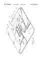
- FIG. 3 is a perspective drawing of the invention's anchoring plate.
- FIG. 4 is a perspective drawing of the invention's gasket.
- FIG. 5 is a cross-sectional drawing of another practical use for FIG. 1 's 2 ⁇ 2 ′ line position.
- FIG. 6 is a perspective drawing of the gasket for the invention's other practical use as illustrated in FIG. 5 .
- FIG. 7 is a vertical cross-sectional drawing of the invention with the penholder installed.
- FIG. 8 is an upward view of FIG. 7 's practical penholder.
- FIG. 9 is a perspective segmented drawing of the penholder's practical use in FIG. 7 .
- FIG. 1 and FIG. 2 Please refer to FIG. 1 and FIG. 2 for the practical use of the assembled invention's beverage stand 1 .
- the principal component of the beverage stand 1 's base 12 is that it's equipped with a shallow indentation 121 .
- base stand plate 120 Within the said indentation is base stand plate 120 , which has the nuts 122 fastened or the screw holes drilled (omitted from the drawings.) Once the screws 5 are all inserted in the gasket 4 , they are screwed in, fastening the anchor 3 of the said beverage stand 1 to an exterior material, which acts as the base.
- the said anchor 3 is produced from a partially soft (a suitable degree of soft and hard) plastic or rubber and can be manufactured as a square, rectangle, circle, oval or other suitable shapes.
- the base plate 30 is installed on the underside of the base 12 's shallow indentation 121 , whose shape, size and depth function in conjunction with raised platform 31 .
- the backside, circling around the rim of the said raised platform 31 is the trough 32 ; upon the raised platform 31 are the holes 33 , and are homologous with the said base plate's nuts 122 or the screw holes.
- the entire raised platform 31 is inserted into the shallow indentation 121 at the bottom of the said base 12 .
- FIG. 4 Please refer to FIG. 4 to examine the gasket 4 .
- This metal plate is pierced during manufacturing to form the gasket body 40 .
- the raise rings 41 Upon the gasket body 40 are the raise rings 41 , and are homologous with the aforementioned nuts 122 or the screw holes.
- the raised rings' thickness must not be thicker than the anchor plate 30 .
- each raised ring 41 is pierced with a hole 42 and then lay the gasket 4 on the underside of the said anchor plate 30 's trough 32 .
- one screw 5 is inserted into each of the said holes 42 .
- the said raised ring 41 may butt against the said base stand plate 120 's nut 122 or directly butt against the said base stand plate 120 .
- the gasket body 40 is pressed tightly against the said anchor plate 30 and secured in the shallow indentation 121 at the bottom of base 12 . Align the holes 33 on the said anchor plate, with the raised ring 41 on the gasket body 40 , thereby allowing the threads of the screws 5 to pass through without touching.
- the beverage stand 1 is pulled, it prevents each hole 33 from becoming damaging.
- the anchor 3 When the invention's beverage stand 1 or similar type material is fastened upon a flat table or desk, as stated previously, the anchor 3 is able to snuggly secure itself by suction, upon the said table or desk surface, making the slightest movement as well as tipping over, quite difficult. However, should one need to remove the beverage stand 1 or change its positioning, one merely lifts up the corner of the anchor plate 30 and the beverage stand 1 easily lifts up off the surface. This speed and convenience is not in the least difficult. In order to make the aforementioned removal of the anchor 3 more convenient, when the anchor 3 is molded, a small protrusion 34 is added to one of the corners of anchor plate 30 . This allows the fingers to pinch the said protrusion 34 and lift up anchor 3 , making it fast and easy.
- the molded raised plateform 31 is inserted into the shallow indentation 121 at the bottom of the beverage stand 1 's base 12 . Its slight thickness is adequate in preventing deforming. As is depicted in FIGS. 2 and 3, the indentations 35 are situated upon the said raised platform 31 and prevent deforming during manufacturing. In addition, the height of the said raised ridge 31 , in principle, will not exceed the depth of the shallow indentation 121 .
- this invention's anchor 3 is designed to use suction upon a table or desk, the said anchor 3 needs to be fastened firmly on the beverage stand 1 . Therefore, as shown in FIGS. 2 and 4, this gasket body must be molded with one circle of extra strength lip 43 or more upon it so as to be inserted securely into the anchor plate 30 's trough 32 . By adding strength and durability to the gasket 4 's gasket body 40 , deforming of its flatness will be prevented.
- FIGS. 5 and 6 Please refer to FIGS. 5 and 6 to see another practical aspect of this invention.
- the practical differences are in the structural modifications of the gasket 4 ′ and screws 5 ′.
- the gasket body 40 ′ is pierced with holes 42 ′ for screws 5 ′ and there are no raised rings 41 (as shown in FIG. 4.)
- the rest of the structure is identical to the original structure.
- the stem of the said screws 5 ′ have a larger diameter shaft 51 , and each said screw 5 ′ is inserted into each hole 42 ′ of the gasket body 40 ′.
- the anchor 3 When the anchor 3 is assembled into the shallow indentation 121 of the beverage stand 1 's base 12 , the said anchor plate 30 's individual holes 33 (as shown in FIG. 3) will be pierced by the said screw 5 's shaft 51 . However the threads of screws 5 ′ will not make any contact with the holes 33 . As the beverage stand 1 is pulled, each hole 33 of the said anchor plate 30 will not
- FIGS. 7, 8 and 9 Please refer to FIGS. 7, 8 and 9 for an even more practical look at this invention.
- This is a direct attachment of a penholder, ashtray or other similar object's underside, and is merely fastened from the holes 33 ′ on the anchor plate 30 ′.
- a shallow indentation 21 is formed into the base of the penholder body 20 of the said penholder 2 .
- nuts 23 or screw holes drilled are Upon the base plate 22 , within the said indentation. After each shaft 51 of the screw 5 ′ is passed directly through the washer 4 a, assemble the anchor 3 ′ upon the shallow indentation 21 's base of penholder 2 or other similar products.
- the shafts 51 , of screws 5 ′ have passed through the flat spacer 4 ′ a and then through the holes 42 ′ of the body 40 ′ a , and then assemble the anchor 3 ′ to the shallow indentation 21 's base of penholder 2 .
- affixing the anchor 3 ′ may complete the penholder 2 or other similar material's base. In this way, the said material may be placed and secured in a position upon a flat table or desk, and it won't shake when bumped or fall over when it's been knocked.
- the penholder 2 or similar material's base is secured in a practical manner to the anchor 3 ′ (as shown in FIG. 7.)
- the said penholder 2 's base plate underside is designed with an appropriate shallow indentation 21 .
- washer 4 a or flat spacer 4 ′ a is assembled and when the partially soft rubber anchor 3 ′ is in the said shallow indentation 21 , the edges of the said anchor plate 30 ′ will form a natural convex shape, like the light lines of FIG. 7 . This will cause the said anchor plate 30 ′ to form into a suction cup. Therefore, when needing to place the penholder material on the table or desk, the said so-called suction of the anchor 3 ′ is secured upon these surfaces with suction.
- Lifting or even sliding the said penholder body 20 becomes impossible. Lifting from any point at the edge of the said anchor plate 30 ′, one must use a finger to lift, or by using one's fingers to pinch the protrusion 34 of the anchor plate 30 ′ and lifting up. In this way, one is able to remove or slide the set.
Landscapes
- Engineering & Computer Science (AREA)
- General Engineering & Computer Science (AREA)
- Mechanical Engineering (AREA)
- Hooks, Suction Cups, And Attachment By Adhesive Means (AREA)
- Furniture Connections (AREA)
- Connection Of Plates (AREA)
Abstract
Description
Claims (3)
Applications Claiming Priority (3)
| Application Number | Priority Date | Filing Date | Title |
|---|---|---|---|
| TW88205706U | 1999-04-14 | ||
| TW088205706U TW396799U (en) | 1999-04-14 | 1999-04-14 | A kind of positioning device for an article |
| CA002303645A CA2303645A1 (en) | 1999-04-14 | 2000-03-31 | Cup anchor |
Publications (1)
| Publication Number | Publication Date |
|---|---|
| US6497394B1 true US6497394B1 (en) | 2002-12-24 |
Family
ID=25681693
Family Applications (1)
| Application Number | Title | Priority Date | Filing Date |
|---|---|---|---|
| US09/342,251 Expired - Fee Related US6497394B1 (en) | 1999-04-14 | 1999-06-29 | Cup anchor |
Country Status (5)
| Country | Link |
|---|---|
| US (1) | US6497394B1 (en) |
| CA (1) | CA2303645A1 (en) |
| DE (1) | DE20006685U1 (en) |
| FR (1) | FR2792390B3 (en) |
| TW (1) | TW396799U (en) |
Cited By (43)
| Publication number | Priority date | Publication date | Assignee | Title |
|---|---|---|---|---|
| US20030075666A1 (en) * | 2001-10-19 | 2003-04-24 | Dunchock Richard Stephen | Plate or bowl anchor |
| US20030161737A1 (en) * | 2002-02-26 | 2003-08-28 | Simon Raab | Stable vacuum adapter |
| US20070218288A1 (en) * | 2006-03-14 | 2007-09-20 | Harald Richter | Adapter plate for supporting a vacuum suction device |
| US20080078296A1 (en) * | 2006-08-08 | 2008-04-03 | Kwok Kuen So | Kitchen Utensil with a Suction Base Mechanism |
| US20090026673A1 (en) * | 2007-07-23 | 2009-01-29 | Clark Sylvester S | Vibration-dampening clip assembly |
| US20090078712A1 (en) * | 2007-09-22 | 2009-03-26 | Israel Harry Zimmerman | Self-anchoring beverage container with directional release and attachment capability |
| US20090108152A1 (en) * | 2007-10-26 | 2009-04-30 | Carnevali Jeffrey D | Suction cup mounting platform |
| US20100239407A1 (en) * | 2009-03-18 | 2010-09-23 | Jesse Russell Mills | Suction plate or bowl holder |
| US20110005673A1 (en) * | 2009-07-09 | 2011-01-13 | Lebauer Ian F | Mounting mat |
| US8757418B2 (en) | 2012-11-01 | 2014-06-24 | Israel Harry Zimmerman | Self-anchoring low-profile container anchor with directional release and attachment capability |
| US8997362B2 (en) | 2012-07-17 | 2015-04-07 | Faro Technologies, Inc. | Portable articulated arm coordinate measuring machine with optical communications bus |
| US9009000B2 (en) | 2010-01-20 | 2015-04-14 | Faro Technologies, Inc. | Method for evaluating mounting stability of articulated arm coordinate measurement machine using inclinometers |
| US9074883B2 (en) | 2009-03-25 | 2015-07-07 | Faro Technologies, Inc. | Device for optically scanning and measuring an environment |
| US9113023B2 (en) | 2009-11-20 | 2015-08-18 | Faro Technologies, Inc. | Three-dimensional scanner with spectroscopic energy detector |
| US9163922B2 (en) | 2010-01-20 | 2015-10-20 | Faro Technologies, Inc. | Coordinate measurement machine with distance meter and camera to determine dimensions within camera images |
| US9168654B2 (en) | 2010-11-16 | 2015-10-27 | Faro Technologies, Inc. | Coordinate measuring machines with dual layer arm |
| US9210288B2 (en) | 2009-11-20 | 2015-12-08 | Faro Technologies, Inc. | Three-dimensional scanner with dichroic beam splitters to capture a variety of signals |
| WO2016010585A1 (en) * | 2014-07-17 | 2016-01-21 | Laurain Lindsey | Surface contact self-sealing integrated tablewear and dining mat |
| US9329271B2 (en) | 2010-05-10 | 2016-05-03 | Faro Technologies, Inc. | Method for optically scanning and measuring an environment |
| US9372265B2 (en) | 2012-10-05 | 2016-06-21 | Faro Technologies, Inc. | Intermediate two-dimensional scanning with a three-dimensional scanner to speed registration |
| US9417056B2 (en) | 2012-01-25 | 2016-08-16 | Faro Technologies, Inc. | Device for optically scanning and measuring an environment |
| US9417316B2 (en) | 2009-11-20 | 2016-08-16 | Faro Technologies, Inc. | Device for optically scanning and measuring an environment |
| US9513107B2 (en) | 2012-10-05 | 2016-12-06 | Faro Technologies, Inc. | Registration calculation between three-dimensional (3D) scans based on two-dimensional (2D) scan data from a 3D scanner |
| US9521919B1 (en) | 2016-04-26 | 2016-12-20 | Yvette Reyes | Self-stabilizing article holder |
| US9529083B2 (en) | 2009-11-20 | 2016-12-27 | Faro Technologies, Inc. | Three-dimensional scanner with enhanced spectroscopic energy detector |
| US9551575B2 (en) | 2009-03-25 | 2017-01-24 | Faro Technologies, Inc. | Laser scanner having a multi-color light source and real-time color receiver |
| US9607239B2 (en) | 2010-01-20 | 2017-03-28 | Faro Technologies, Inc. | Articulated arm coordinate measurement machine having a 2D camera and method of obtaining 3D representations |
| US9628775B2 (en) | 2010-01-20 | 2017-04-18 | Faro Technologies, Inc. | Articulated arm coordinate measurement machine having a 2D camera and method of obtaining 3D representations |
| US9814332B2 (en) | 2015-06-29 | 2017-11-14 | Israel Harry Zimmerman | Anchoring device with directional release and attachment capability and protection against inadvertent release |
| US20180199542A1 (en) * | 2015-06-11 | 2018-07-19 | Green Oak Technology Group Llc | Tip-proof feeding bowl for house pets |
| US10067231B2 (en) | 2012-10-05 | 2018-09-04 | Faro Technologies, Inc. | Registration calculation of three-dimensional scanner data performed between scans based on measurements by two-dimensional scanner |
| US20180368594A1 (en) * | 2016-08-10 | 2018-12-27 | Admar International, Inc. | Feeding mat |
| US10175037B2 (en) | 2015-12-27 | 2019-01-08 | Faro Technologies, Inc. | 3-D measuring device with battery pack |
| US10267453B2 (en) * | 2006-03-03 | 2019-04-23 | Charles L. Casagrande | Mounting system and accessory components |
| US10281259B2 (en) | 2010-01-20 | 2019-05-07 | Faro Technologies, Inc. | Articulated arm coordinate measurement machine that uses a 2D camera to determine 3D coordinates of smoothly continuous edge features |
| US11065401B2 (en) * | 2018-11-21 | 2021-07-20 | Shl Medical Ag | Stand for medicament delivery device, and system comprising stand and medicament delivery device |
| WO2021250458A1 (en) * | 2019-07-09 | 2021-12-16 | Lawson Darren W | Vacuum lifting system |
| US11255482B1 (en) | 2020-12-30 | 2022-02-22 | Israel Harry Zimmerman | Quick-release anchoring apparatus with acceleration damping |
| US20220133597A1 (en) * | 2020-06-16 | 2022-05-05 | Anjellica Williams | Baby bottle retaining sleeve |
| US11415266B2 (en) | 2020-12-30 | 2022-08-16 | Israel Harry Zimmerman | Quick-release anchoring apparatus with self-mounted anchor member |
| US11522988B2 (en) | 2021-04-09 | 2022-12-06 | Mighty Ventures, Inc. | Object holder with quick-release anchoring capability |
| US11525475B2 (en) | 2021-03-03 | 2022-12-13 | Mighty Ventures, Inc. | Object holder with quick-release anchoring capability |
| US11542980B2 (en) | 2020-12-30 | 2023-01-03 | Israel Harry Zimmerman | Universal quick-release anchor member |
Citations (12)
| Publication number | Priority date | Publication date | Assignee | Title |
|---|---|---|---|---|
| US4756497A (en) * | 1986-09-08 | 1988-07-12 | Lan Yung Huei | Non-turnover base device |
| US4759525A (en) * | 1987-07-09 | 1988-07-26 | Sun Company | Attachable beverage coaster |
| US5014956A (en) * | 1989-03-02 | 1991-05-14 | Nk Innovations, Inc. | Adjustable drink holder |
| US5180132A (en) * | 1991-11-22 | 1993-01-19 | Pearson Scott A | Self-setting suction holder device |
| USD351970S (en) * | 1993-05-03 | 1994-11-01 | Robert Barrio | Baby food jar holder |
| US5516019A (en) * | 1994-05-16 | 1996-05-14 | Moon; Soo M. | Carrier |
| US5961086A (en) * | 1998-04-27 | 1999-10-05 | Beckman Coulter, Inc. | Hands-free gripping device for containers |
| US5970860A (en) * | 1999-01-08 | 1999-10-26 | Yip; Chung Lun | Food processor |
| USD416764S (en) * | 1999-02-11 | 1999-11-23 | Wayne E Gagne | Suction cup beverage holder |
| US5996950A (en) * | 1996-11-22 | 1999-12-07 | Richter; Herbert | Suction cup mounting arrangement |
| US6045111A (en) * | 1998-08-10 | 2000-04-04 | Chien Lu Hardware Co., Ltd. | Fixing sucker structure |
| US6047938A (en) * | 1998-05-14 | 2000-04-11 | Mitchell; Jerry | Beverage coaster and dispenser |
-
1999
- 1999-04-14 TW TW088205706U patent/TW396799U/en not_active IP Right Cessation
- 1999-06-29 US US09/342,251 patent/US6497394B1/en not_active Expired - Fee Related
-
2000
- 2000-03-31 CA CA002303645A patent/CA2303645A1/en not_active Abandoned
- 2000-04-11 DE DE20006685U patent/DE20006685U1/en not_active Expired - Lifetime
- 2000-04-13 FR FR0004776A patent/FR2792390B3/en not_active Expired - Fee Related
Patent Citations (12)
| Publication number | Priority date | Publication date | Assignee | Title |
|---|---|---|---|---|
| US4756497A (en) * | 1986-09-08 | 1988-07-12 | Lan Yung Huei | Non-turnover base device |
| US4759525A (en) * | 1987-07-09 | 1988-07-26 | Sun Company | Attachable beverage coaster |
| US5014956A (en) * | 1989-03-02 | 1991-05-14 | Nk Innovations, Inc. | Adjustable drink holder |
| US5180132A (en) * | 1991-11-22 | 1993-01-19 | Pearson Scott A | Self-setting suction holder device |
| USD351970S (en) * | 1993-05-03 | 1994-11-01 | Robert Barrio | Baby food jar holder |
| US5516019A (en) * | 1994-05-16 | 1996-05-14 | Moon; Soo M. | Carrier |
| US5996950A (en) * | 1996-11-22 | 1999-12-07 | Richter; Herbert | Suction cup mounting arrangement |
| US5961086A (en) * | 1998-04-27 | 1999-10-05 | Beckman Coulter, Inc. | Hands-free gripping device for containers |
| US6047938A (en) * | 1998-05-14 | 2000-04-11 | Mitchell; Jerry | Beverage coaster and dispenser |
| US6045111A (en) * | 1998-08-10 | 2000-04-04 | Chien Lu Hardware Co., Ltd. | Fixing sucker structure |
| US5970860A (en) * | 1999-01-08 | 1999-10-26 | Yip; Chung Lun | Food processor |
| USD416764S (en) * | 1999-02-11 | 1999-11-23 | Wayne E Gagne | Suction cup beverage holder |
Cited By (62)
| Publication number | Priority date | Publication date | Assignee | Title |
|---|---|---|---|---|
| US20030075666A1 (en) * | 2001-10-19 | 2003-04-24 | Dunchock Richard Stephen | Plate or bowl anchor |
| US20030161737A1 (en) * | 2002-02-26 | 2003-08-28 | Simon Raab | Stable vacuum adapter |
| US7296979B2 (en) * | 2002-02-26 | 2007-11-20 | Faro Technologies Inc. | Stable vacuum mounting plate adapter |
| US10801665B2 (en) * | 2006-03-03 | 2020-10-13 | Charles L. Casagrande | Mounting system and accessory components |
| US10267453B2 (en) * | 2006-03-03 | 2019-04-23 | Charles L. Casagrande | Mounting system and accessory components |
| US20070218288A1 (en) * | 2006-03-14 | 2007-09-20 | Harald Richter | Adapter plate for supporting a vacuum suction device |
| US20080078296A1 (en) * | 2006-08-08 | 2008-04-03 | Kwok Kuen So | Kitchen Utensil with a Suction Base Mechanism |
| US20090026673A1 (en) * | 2007-07-23 | 2009-01-29 | Clark Sylvester S | Vibration-dampening clip assembly |
| US8028850B2 (en) * | 2007-09-22 | 2011-10-04 | Israel Harry Zimmerman | Self-anchoring beverage container with directional release and attachment capability |
| US20090078712A1 (en) * | 2007-09-22 | 2009-03-26 | Israel Harry Zimmerman | Self-anchoring beverage container with directional release and attachment capability |
| US20100187240A1 (en) * | 2007-09-22 | 2010-07-29 | Israel Harry Zimmerman | Self-anchoring beverage container with directional release and attachment capability |
| US8025169B2 (en) * | 2007-09-22 | 2011-09-27 | Israel Harry Zimmerman | Self-anchoring beverage container with directional release and attachment capability |
| US20090108152A1 (en) * | 2007-10-26 | 2009-04-30 | Carnevali Jeffrey D | Suction cup mounting platform |
| US8231089B2 (en) * | 2009-03-18 | 2012-07-31 | Lil Diner, Llc | Suction plate or bowl holder |
| US20100239407A1 (en) * | 2009-03-18 | 2010-09-23 | Jesse Russell Mills | Suction plate or bowl holder |
| US9074883B2 (en) | 2009-03-25 | 2015-07-07 | Faro Technologies, Inc. | Device for optically scanning and measuring an environment |
| US9551575B2 (en) | 2009-03-25 | 2017-01-24 | Faro Technologies, Inc. | Laser scanner having a multi-color light source and real-time color receiver |
| US20110005673A1 (en) * | 2009-07-09 | 2011-01-13 | Lebauer Ian F | Mounting mat |
| US9417316B2 (en) | 2009-11-20 | 2016-08-16 | Faro Technologies, Inc. | Device for optically scanning and measuring an environment |
| US9113023B2 (en) | 2009-11-20 | 2015-08-18 | Faro Technologies, Inc. | Three-dimensional scanner with spectroscopic energy detector |
| US9529083B2 (en) | 2009-11-20 | 2016-12-27 | Faro Technologies, Inc. | Three-dimensional scanner with enhanced spectroscopic energy detector |
| US9210288B2 (en) | 2009-11-20 | 2015-12-08 | Faro Technologies, Inc. | Three-dimensional scanner with dichroic beam splitters to capture a variety of signals |
| US10281259B2 (en) | 2010-01-20 | 2019-05-07 | Faro Technologies, Inc. | Articulated arm coordinate measurement machine that uses a 2D camera to determine 3D coordinates of smoothly continuous edge features |
| US9628775B2 (en) | 2010-01-20 | 2017-04-18 | Faro Technologies, Inc. | Articulated arm coordinate measurement machine having a 2D camera and method of obtaining 3D representations |
| US9009000B2 (en) | 2010-01-20 | 2015-04-14 | Faro Technologies, Inc. | Method for evaluating mounting stability of articulated arm coordinate measurement machine using inclinometers |
| US10060722B2 (en) | 2010-01-20 | 2018-08-28 | Faro Technologies, Inc. | Articulated arm coordinate measurement machine having a 2D camera and method of obtaining 3D representations |
| US9163922B2 (en) | 2010-01-20 | 2015-10-20 | Faro Technologies, Inc. | Coordinate measurement machine with distance meter and camera to determine dimensions within camera images |
| US9607239B2 (en) | 2010-01-20 | 2017-03-28 | Faro Technologies, Inc. | Articulated arm coordinate measurement machine having a 2D camera and method of obtaining 3D representations |
| US9329271B2 (en) | 2010-05-10 | 2016-05-03 | Faro Technologies, Inc. | Method for optically scanning and measuring an environment |
| US9684078B2 (en) | 2010-05-10 | 2017-06-20 | Faro Technologies, Inc. | Method for optically scanning and measuring an environment |
| US9168654B2 (en) | 2010-11-16 | 2015-10-27 | Faro Technologies, Inc. | Coordinate measuring machines with dual layer arm |
| US9417056B2 (en) | 2012-01-25 | 2016-08-16 | Faro Technologies, Inc. | Device for optically scanning and measuring an environment |
| US8997362B2 (en) | 2012-07-17 | 2015-04-07 | Faro Technologies, Inc. | Portable articulated arm coordinate measuring machine with optical communications bus |
| US10067231B2 (en) | 2012-10-05 | 2018-09-04 | Faro Technologies, Inc. | Registration calculation of three-dimensional scanner data performed between scans based on measurements by two-dimensional scanner |
| US10203413B2 (en) | 2012-10-05 | 2019-02-12 | Faro Technologies, Inc. | Using a two-dimensional scanner to speed registration of three-dimensional scan data |
| US9739886B2 (en) | 2012-10-05 | 2017-08-22 | Faro Technologies, Inc. | Using a two-dimensional scanner to speed registration of three-dimensional scan data |
| US9746559B2 (en) | 2012-10-05 | 2017-08-29 | Faro Technologies, Inc. | Using two-dimensional camera images to speed registration of three-dimensional scans |
| US11815600B2 (en) | 2012-10-05 | 2023-11-14 | Faro Technologies, Inc. | Using a two-dimensional scanner to speed registration of three-dimensional scan data |
| US11112501B2 (en) | 2012-10-05 | 2021-09-07 | Faro Technologies, Inc. | Using a two-dimensional scanner to speed registration of three-dimensional scan data |
| US11035955B2 (en) | 2012-10-05 | 2021-06-15 | Faro Technologies, Inc. | Registration calculation of three-dimensional scanner data performed between scans based on measurements by two-dimensional scanner |
| US9618620B2 (en) | 2012-10-05 | 2017-04-11 | Faro Technologies, Inc. | Using depth-camera images to speed registration of three-dimensional scans |
| US9513107B2 (en) | 2012-10-05 | 2016-12-06 | Faro Technologies, Inc. | Registration calculation between three-dimensional (3D) scans based on two-dimensional (2D) scan data from a 3D scanner |
| US10739458B2 (en) | 2012-10-05 | 2020-08-11 | Faro Technologies, Inc. | Using two-dimensional camera images to speed registration of three-dimensional scans |
| US9372265B2 (en) | 2012-10-05 | 2016-06-21 | Faro Technologies, Inc. | Intermediate two-dimensional scanning with a three-dimensional scanner to speed registration |
| US8757418B2 (en) | 2012-11-01 | 2014-06-24 | Israel Harry Zimmerman | Self-anchoring low-profile container anchor with directional release and attachment capability |
| RU2637097C1 (en) * | 2014-07-17 | 2017-11-29 | Лаураин Линдсей | Set of tableware and napkin napkin that is self-adherent due to surface contact |
| EP3169196B1 (en) | 2014-07-17 | 2021-09-29 | Laurain, Lindsey | Surface contact self-sealing integrated tablewear and dining mat |
| WO2016010585A1 (en) * | 2014-07-17 | 2016-01-21 | Laurain Lindsey | Surface contact self-sealing integrated tablewear and dining mat |
| US20180199542A1 (en) * | 2015-06-11 | 2018-07-19 | Green Oak Technology Group Llc | Tip-proof feeding bowl for house pets |
| US9814332B2 (en) | 2015-06-29 | 2017-11-14 | Israel Harry Zimmerman | Anchoring device with directional release and attachment capability and protection against inadvertent release |
| US10175037B2 (en) | 2015-12-27 | 2019-01-08 | Faro Technologies, Inc. | 3-D measuring device with battery pack |
| US9521919B1 (en) | 2016-04-26 | 2016-12-20 | Yvette Reyes | Self-stabilizing article holder |
| US20180368594A1 (en) * | 2016-08-10 | 2018-12-27 | Admar International, Inc. | Feeding mat |
| US11065401B2 (en) * | 2018-11-21 | 2021-07-20 | Shl Medical Ag | Stand for medicament delivery device, and system comprising stand and medicament delivery device |
| WO2021250458A1 (en) * | 2019-07-09 | 2021-12-16 | Lawson Darren W | Vacuum lifting system |
| US20220133597A1 (en) * | 2020-06-16 | 2022-05-05 | Anjellica Williams | Baby bottle retaining sleeve |
| US11415266B2 (en) | 2020-12-30 | 2022-08-16 | Israel Harry Zimmerman | Quick-release anchoring apparatus with self-mounted anchor member |
| US11542980B2 (en) | 2020-12-30 | 2023-01-03 | Israel Harry Zimmerman | Universal quick-release anchor member |
| US11255482B1 (en) | 2020-12-30 | 2022-02-22 | Israel Harry Zimmerman | Quick-release anchoring apparatus with acceleration damping |
| US11846389B2 (en) | 2020-12-30 | 2023-12-19 | Israel Harry Zimmerman | Quick-release anchoring apparatus with self-mounted anchor member |
| US11525475B2 (en) | 2021-03-03 | 2022-12-13 | Mighty Ventures, Inc. | Object holder with quick-release anchoring capability |
| US11522988B2 (en) | 2021-04-09 | 2022-12-06 | Mighty Ventures, Inc. | Object holder with quick-release anchoring capability |
Also Published As
| Publication number | Publication date |
|---|---|
| FR2792390A3 (en) | 2000-10-20 |
| CA2303645A1 (en) | 2001-09-30 |
| TW396799U (en) | 2000-07-01 |
| DE20006685U1 (en) | 2000-09-28 |
| FR2792390B3 (en) | 2001-03-09 |
Similar Documents
| Publication | Publication Date | Title |
|---|---|---|
| US6497394B1 (en) | Cup anchor | |
| US2784577A (en) | Weighted coaster | |
| US6405982B2 (en) | Self-attaching sliding support for articles of furniture | |
| USD947122S1 (en) | Charging dock for serum device | |
| US4830320A (en) | Device for supporting and stabilizing an article of furniture | |
| US20170280904A1 (en) | Surface Contact Self-Sealing Integrated Tablewear and Dining Mat | |
| US2111456A (en) | Device for holding fowls and the like | |
| US20100176253A1 (en) | Apparatus for connecting sucking plate and tablewares for table provided with the same | |
| USD887829S1 (en) | Container | |
| US6029829A (en) | Ring pad for a jewelry tray | |
| US3219226A (en) | Food serving device | |
| CA2412649A1 (en) | A child's plate | |
| KR200396052Y1 (en) | Desk | |
| US2872046A (en) | Book ends | |
| US20030075666A1 (en) | Plate or bowl anchor | |
| USD946388S1 (en) | Cushion for furniture leg | |
| USD915583S1 (en) | Incontinence article | |
| JP3210400U (en) | Glass holder | |
| US11375832B2 (en) | Learning tableware set | |
| USD495388S1 (en) | Tee | |
| USD1010461S1 (en) | Receptacle | |
| JP3183347U (en) | A vessel with an inclined edge | |
| US20210022530A1 (en) | Cup resistant to both slipping and tipping | |
| KR200457306Y1 (en) | a crosspiece | |
| US10602862B2 (en) | Secure-grip disposable dish for food |
Legal Events
| Date | Code | Title | Description |
|---|---|---|---|
| AS | Assignment |
Owner name: CHIEN, TA HSUN, TAIWAN Free format text: ASSIGNMENT OF ASSIGNORS INTEREST;ASSIGNOR:DUNCHOCK, RICHARD STEPHEN;REEL/FRAME:017718/0424 Effective date: 20060605 Owner name: HUANG, PEI HSIU, TAIWAN Free format text: ASSIGNMENT OF ASSIGNORS INTEREST;ASSIGNOR:DUNCHOCK, RICHARD STEPHEN;REEL/FRAME:017718/0424 Effective date: 20060605 |
|
| FPAY | Fee payment |
Year of fee payment: 4 |
|
| FPAY | Fee payment |
Year of fee payment: 8 |
|
| REMI | Maintenance fee reminder mailed | ||
| LAPS | Lapse for failure to pay maintenance fees | ||
| STCH | Information on status: patent discontinuation |
Free format text: PATENT EXPIRED DUE TO NONPAYMENT OF MAINTENANCE FEES UNDER 37 CFR 1.362 |
|
| FP | Lapsed due to failure to pay maintenance fee |
Effective date: 20141224 |