US6494178B1 - Combustion chamber including piston for a spark-ignition, direct-injection combustion system - Google Patents
Combustion chamber including piston for a spark-ignition, direct-injection combustion system Download PDFInfo
- Publication number
- US6494178B1 US6494178B1 US09/930,707 US93070701A US6494178B1 US 6494178 B1 US6494178 B1 US 6494178B1 US 93070701 A US93070701 A US 93070701A US 6494178 B1 US6494178 B1 US 6494178B1
- Authority
- US
- United States
- Prior art keywords
- piston
- bowl
- combustion chamber
- exhaust
- range
- Prior art date
- Legal status (The legal status is an assumption and is not a legal conclusion. Google has not performed a legal analysis and makes no representation as to the accuracy of the status listed.)
- Expired - Fee Related
Links
- 238000002485 combustion reaction Methods 0.000 title claims abstract description 48
- 238000002347 injection Methods 0.000 title claims description 9
- 239000007924 injection Substances 0.000 title claims description 9
- 239000000446 fuel Substances 0.000 claims abstract description 29
- 230000002093 peripheral effect Effects 0.000 claims description 7
- 239000000203 mixture Substances 0.000 description 6
- 230000006835 compression Effects 0.000 description 2
- 238000007906 compression Methods 0.000 description 2
- 239000007921 spray Substances 0.000 description 2
- 238000013459 approach Methods 0.000 description 1
- 239000007789 gas Substances 0.000 description 1
- 230000003993 interaction Effects 0.000 description 1
Images


Classifications
-
- F—MECHANICAL ENGINEERING; LIGHTING; HEATING; WEAPONS; BLASTING
- F02—COMBUSTION ENGINES; HOT-GAS OR COMBUSTION-PRODUCT ENGINE PLANTS
- F02B—INTERNAL-COMBUSTION PISTON ENGINES; COMBUSTION ENGINES IN GENERAL
- F02B23/00—Other engines characterised by special shape or construction of combustion chambers to improve operation
- F02B23/08—Other engines characterised by special shape or construction of combustion chambers to improve operation with positive ignition
- F02B23/10—Other engines characterised by special shape or construction of combustion chambers to improve operation with positive ignition with separate admission of air and fuel into cylinder
- F02B23/104—Other engines characterised by special shape or construction of combustion chambers to improve operation with positive ignition with separate admission of air and fuel into cylinder the injector being placed on a side position of the cylinder
-
- F—MECHANICAL ENGINEERING; LIGHTING; HEATING; WEAPONS; BLASTING
- F02—COMBUSTION ENGINES; HOT-GAS OR COMBUSTION-PRODUCT ENGINE PLANTS
- F02F—CYLINDERS, PISTONS OR CASINGS, FOR COMBUSTION ENGINES; ARRANGEMENTS OF SEALINGS IN COMBUSTION ENGINES
- F02F3/00—Pistons
- F02F3/26—Pistons having combustion chamber in piston head
-
- F—MECHANICAL ENGINEERING; LIGHTING; HEATING; WEAPONS; BLASTING
- F02—COMBUSTION ENGINES; HOT-GAS OR COMBUSTION-PRODUCT ENGINE PLANTS
- F02B—INTERNAL-COMBUSTION PISTON ENGINES; COMBUSTION ENGINES IN GENERAL
- F02B75/00—Other engines
- F02B75/12—Other methods of operation
- F02B2075/125—Direct injection in the combustion chamber for spark ignition engines, i.e. not in pre-combustion chamber
-
- Y—GENERAL TAGGING OF NEW TECHNOLOGICAL DEVELOPMENTS; GENERAL TAGGING OF CROSS-SECTIONAL TECHNOLOGIES SPANNING OVER SEVERAL SECTIONS OF THE IPC; TECHNICAL SUBJECTS COVERED BY FORMER USPC CROSS-REFERENCE ART COLLECTIONS [XRACs] AND DIGESTS
- Y02—TECHNOLOGIES OR APPLICATIONS FOR MITIGATION OR ADAPTATION AGAINST CLIMATE CHANGE
- Y02T—CLIMATE CHANGE MITIGATION TECHNOLOGIES RELATED TO TRANSPORTATION
- Y02T10/00—Road transport of goods or passengers
- Y02T10/10—Internal combustion engine [ICE] based vehicles
- Y02T10/12—Improving ICE efficiencies
Definitions
- This invention relates to pistons for use in engines having direct-injection fuel systems.
- Spark-ignition, direct-injection combustion systems for internal combustion engines have been proposed to improve fuel economy when compared with more typical port fuel-injected combustion systems.
- the spark-ignition, direct-injection engine is provided with a high pressure fuel injection system that sprays fuel directly into the engine combustion chamber which is formed, at least partially, in the piston.
- the fuel is directed or transported to a specific region within the combustion chamber. This creates a stratified charge in the combustion chamber resulting in fuel economy benefits since the throttling requirements are less restrictive and the fuel combustion characteristics are improved. It has become the practice of engine designers to incorporate design features in the piston toward this end.
- U.S. Pat. No. 5,553,588 issued Sep. 10, 1996 discloses a combustion chamber design with improved fuel distribution in mind.
- This prior art describes a combustion chamber that is partially formed in the piston.
- the combustion chamber has a plurality of fuel regions defined by walls including two arcuate-shaped regions interconnected by a linear region. These regions cooperate to accommodate swirling of the fuel entering the combustion chamber.
- the ignition source a spark plug, is positioned with the electrodes protruding into the combustion chamber near the linear region and the fuel is injected at one of the arcuate regions.
- U.S. Pat. No. 6,035,823, issued Mar. 14, 2000 describes a piston, injector and igniter combination wherein the piston has a circumferential wall having a predetermined radius and wherein the center of the circumferential wall is located a predetermined distance from the injector.
- the circumferential wall has an arc-shaped cross section that redirects the fuel toward the igniter.
- the piston configuration of this patent requires that the injector have a flat sector-shaped spray pattern.
- the combustion chamber is formed between a cylinder head and a piston with a piston bowl being formed therein.
- the piston bowl has a floor and a transporting surface.
- the combustion chamber has exhaust squish surfaces and intake squish surfaces formed between the piston external of the bowl and a combustion chamber surface on the cylinder head.
- the piston bowl volume is in the range of 50% to 70% of the total volume of the combustion chamber at piston top dead center.
- the bowl depth and the location of the transporting surface have dimensional ranges that are essential to the present invention.
- the exhaust squish heights are in a range of 2-6 mm.
- the upper edge of the transporting surface is located in the range of 6-10 mm from the centerline of the ignition source and has an included negative draft angle in the range of 0 to ⁇ 20 degrees.
- the bed of the bowl and a flat portion or the upper edge of the transporting surface are connected by an arcuate surface that is tangential to both.
- FIG. 1 is an isometric view of a portion of an engine containing a piston and a portion of a cylinder head with the intake and exhaust valves, the ignition source and the fuel injector incorporating the present invention.
- FIG. 2 is an isometric view of a piston incorporating the present invention.
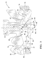
- FIG. 3 is a partial cross-sectional elevational view of a piston and cylinder head incorporating the present invention.
- a portion of an engine 10 includes a piston 12 and a cylinder head 14 .
- the cylinder head 14 has a primary inlet port 16 , a secondary inlet port 18 , a pair of outlet ports 20 and 22 , an ignition source or spark plug 24 , a fuel injector 26 , two inlet valves 28 and 30 and two exhaust valves 32 and 34 .
- the spark plug 24 is a conventional device that supplies an ignition source or spark to the combustion chamber 36 formed between the piston 12 , a cylinder wall or bore 37 , and the cylinder head 14 .
- the fuel injector 26 is a conventional direct injection device that is designed to inject fuel into the combustion chamber 36 during engine operation. The amount and timing of the fuel injection is controlled by a conventional electronic control unit (ECU) that includes a programmable digital computer. These control devices are well known to those skilled in the art of engine design.
- ECU electronice control unit
- the inlet valve 28 controls the flow of air into the combustion chamber 36 through the primary inlet port 16
- the inlet valve 30 controls the flow of air into the combustion chamber 36 through the secondary inlet port 18
- the exhaust valves 32 and 34 control the flow of exhaust products from the combustion chamber 36 through the exhaust ports 20 and 22 , respectively.
- the opening and closing of the valves 28 , 30 , 32 and 34 is controlled in a conventional manner such as through the employment of a cam mechanism, not shown.
- the piston 12 has a bowl 38 formed therein.
- the combustion chamber 36 includes a bowl volume 40 and a volume space 42 .
- the bowl volume 40 consists of the volume of the bowl 38 and the space between the bowl 38 and the cylinder head 14 .
- the volume space 42 includes the volume between the cylinder head 14 and the piston 12 external to the periphery of the bowl 38 .
- the bowl 38 has a floor 44 , an inner edge of a rim surface 46 , inner edges of exhaust squish surfaces 48 and 50 , inner edges of inlet squish surfaces 52 and 54 , a transporting surface 55 , and three side surfaces 56 , 57 and 58 that connect with the transporting surface 55 to surround the bowl and extend upward to the edges of, respectively, the rim surface 46 , the inlet squish surfaces 52 and 54 , and the linear edge 63 that forms the inner edges of the exhaust squish surfaces 48 and 50 .
- the transporting surface 55 includes a bowl radius 60 , having a dimension in the range of from 3 to 12 mm, and, optionally, a flat surface 62 . Together, the bowl radius and the flat surface, if provided, extend upward from the floor 44 to a substantially linear edge 63 .
- the floor 44 and the flat surface 62 are tangential to the bowl radius 60 .
- the flat surface 62 (or the upper edge of the bowl radius 60 if there is no flat surface) intersects the squish surfaces 48 and 50 at a negative draft angle 64 (FIG. 3) in the range of 0 to ⁇ 20 degrees, relative to the axis 66 of the cylinder bore 37 .
- the side surface 56 is formed as a radius surface that connects tangentially with the floor 44 and the side surfaces 57 and 58 also connect with the floor by tangential radii, not clearly shown.
- the rim surface 46 is spaced a distance 74 (3 to 8 mm) from the floor 44 .
- the exhaust squish surface 48 is positioned opposite the exhaust valve 32 and the exhaust squish surface 50 is positioned opposite the exhaust valve 34 .
- the intake squish surfaces 52 and 54 are positioned opposite the intake valves 28 and 30 , respectively.
- the squish clearance or distance 76 between the cylinder head 14 and the respective squish surfaces 48 , 50 , 52 and 54 is in the range of 2 to 6 mm.
- the volume ratio (VR) of the bowl volume (VB) to total combustion chamber volume (VT) at top dead center is also an important design parameter insuring that proper combustion will occur.
- the total volume of the combustion chamber 36 at top dead center is the space volume 42 plus the bowl volume 40 .
- a peripheral surface 78 extends around the outer edge of the piston 12 from the inlet squish surface 52 past the exhaust squish surfaces 48 and 50 to the inlet squish surface 54 .
- the peripheral surface 78 is an extension of the rim surface 46 and has a radial dimension in the range of 0 to 6 mm.
- the outer edges of the peripheral surface 78 and the rim surface 46 essentially define the outer edge of the piston 12 and, due to the close proximity of the cylinder wall 37 , the outer periphery of the combustion chamber 36 .
- the piston 12 When the engine is operating in a stratified charge combustion mode, the piston 12 is reciprocated in the cylinder bore 37 such that the combustion chamber 36 expands and contracts during the operating cycle of the engine.
- the intake stroke one or both of the intake valves 28 , 30 are opened to admit an air mass into the cylinder bore.
- the valves are closed and the air mass is compressed as the piston approaches top dead center.
- fuel is injected directly into the combustion chamber 36 by the fuel injector 26 to mix with the air mass. The amount and timing of fuel injected is controlled by the ECU.
- the fuel-air mixture is ignited by the spark plug 24 at or slightly before top dead center. The ignited mixture is rapidly expanded as the piston moves down during the power stroke.
- the exhaust valves 32 and 34 are opened and the piston 12 again moves upward toward the cylinder head 14 during the exhaust stroke so that the exhaust gases are forced from the cylinder bore.
- the intake stroke is then repeated.
- the engine will be operated as described above to create stratified charges in the combustion chamber to permit the ignition of lean fuel-air mixtures under low and intermediate loads.
- a homogeneous fuel distribution mode may be used. In this mode, the fuel will be injected during the intake stroke to mix with the inlet air prior to interaction with the piston bowl features described, which are provided primarily for stratified charge operation.
Landscapes
- Engineering & Computer Science (AREA)
- Chemical & Material Sciences (AREA)
- Combustion & Propulsion (AREA)
- Mechanical Engineering (AREA)
- General Engineering & Computer Science (AREA)
- Combustion Methods Of Internal-Combustion Engines (AREA)
Abstract
Description
Claims (5)
Priority Applications (1)
| Application Number | Priority Date | Filing Date | Title |
|---|---|---|---|
| US09/930,707 US6494178B1 (en) | 2001-08-13 | 2001-08-13 | Combustion chamber including piston for a spark-ignition, direct-injection combustion system |
Applications Claiming Priority (1)
| Application Number | Priority Date | Filing Date | Title |
|---|---|---|---|
| US09/930,707 US6494178B1 (en) | 2001-08-13 | 2001-08-13 | Combustion chamber including piston for a spark-ignition, direct-injection combustion system |
Publications (1)
| Publication Number | Publication Date |
|---|---|
| US6494178B1 true US6494178B1 (en) | 2002-12-17 |
Family
ID=25459635
Family Applications (1)
| Application Number | Title | Priority Date | Filing Date |
|---|---|---|---|
| US09/930,707 Expired - Fee Related US6494178B1 (en) | 2001-08-13 | 2001-08-13 | Combustion chamber including piston for a spark-ignition, direct-injection combustion system |
Country Status (1)
| Country | Link |
|---|---|
| US (1) | US6494178B1 (en) |
Cited By (39)
| Publication number | Priority date | Publication date | Assignee | Title |
|---|---|---|---|---|
| US6588396B1 (en) * | 2002-02-01 | 2003-07-08 | General Motors Corporation | Spark ignition direct injection engine with oval fuel spray into oblong piston bowl |
| US6651611B2 (en) * | 2002-04-25 | 2003-11-25 | General Motors Corporation | Combustion chamber for swirl flow two valve spark ignition direct injection engine |
| US20040007202A1 (en) * | 1998-07-08 | 2004-01-15 | Toyota Jidosha Kabushiki Kaisha | Direct cylinder injection-type spark ignition internal combustion engine |
| US20040216715A1 (en) * | 2001-12-05 | 2004-11-04 | Baverische Motoren Werke. | Combustion process with charge stratification for an internal combustion engine with direct injection and spark ignition |
| US6910455B2 (en) * | 2002-03-13 | 2005-06-28 | Ford Global Technologies, Llc | Spark ignition engine with shallow bowl-in-piston geometry |
| US20050205050A1 (en) * | 2004-03-17 | 2005-09-22 | Nissan Motor Co., Ltd. | Internal combustion engine with auxiliary combustion chamber |
| US6971365B1 (en) * | 2004-07-12 | 2005-12-06 | General Motors Corporation | Auto-ignition gasoline engine combustion chamber and method |
| WO2006017051A3 (en) * | 2004-07-12 | 2006-04-27 | Gen Motors Corp | Auto-ignition gasoline engine combustion chamber and method |
| US20060185642A1 (en) * | 2005-02-18 | 2006-08-24 | Mitsubishi Jidosha Kogyo Kabushiki Kaisha | Combustion engine chamber |
| US20060260584A1 (en) * | 2003-11-22 | 2006-11-23 | Jorg Ballauf | Reciprocating internal-combustion engine with direct fuel injection by means of an injector arranged on the intake side |
| US20070235004A1 (en) * | 2006-04-10 | 2007-10-11 | Jianwen Yi | Bowl-in-piston of a cylinder in a direct injection engine |
| US7353797B1 (en) | 2007-02-28 | 2008-04-08 | University Of Washington | Combustion chamber for internal combustion engine |
| US20080156081A1 (en) * | 2005-11-16 | 2008-07-03 | University Of Michigan@@Gm Global Technology Operations, Inc. | Method and apparatus to determine magnitude of combustion chamber deposits |
| US20080271699A1 (en) * | 2005-06-27 | 2008-11-06 | Jens Wellev | Combustion Engine |
| WO2009020488A1 (en) * | 2007-08-07 | 2009-02-12 | Scuderi Group, Llc | Spark plug location for split-cycle engine |
| US20100132662A1 (en) * | 2008-12-02 | 2010-06-03 | Hyundai Motor Copmpany | Piston of Gasoline Direct Injection Engine |
| WO2011028284A1 (en) * | 2009-09-01 | 2011-03-10 | Ecomotors Inc. | Non-soot emitting fuel combustion chamber |
| US20110120410A1 (en) * | 2009-11-26 | 2011-05-26 | Hyundai Motor Company | Gasoline direct injection engine |
| FR2976978A1 (en) * | 2011-06-24 | 2012-12-28 | Peugeot Citroen Automobiles Sa | PISTON FOR COMBUSTION CHAMBER OF INTERNAL COMBUSTION ENGINE |
| CN103696847A (en) * | 2012-09-28 | 2014-04-02 | 重庆长安汽车股份有限公司 | In-cylinder direct injection engine combustion chamber |
| US20170082080A1 (en) * | 2015-09-23 | 2017-03-23 | Andreas Kemptner | Ignition device for an extraneously igniting combustion piston engine |
| US10316734B2 (en) * | 2016-10-05 | 2019-06-11 | Caterpillar Inc. | Piston and cylinder features for enhanced squish flow |
| US10323602B2 (en) | 2017-08-14 | 2019-06-18 | GM Global Technology Operations LLC | Piston bowl rim with fatigue resistance |
| US10465629B2 (en) | 2017-03-30 | 2019-11-05 | Quest Engines, LLC | Internal combustion engine having piston with deflector channels and complementary cylinder head |
| US10526953B2 (en) | 2017-03-30 | 2020-01-07 | Quest Engines, LLC | Internal combustion engine |
| US10590813B2 (en) | 2017-03-30 | 2020-03-17 | Quest Engines, LLC | Internal combustion engine |
| US10590834B2 (en) | 2017-03-30 | 2020-03-17 | Quest Engines, LLC | Internal combustion engine |
| US10598285B2 (en) | 2017-03-30 | 2020-03-24 | Quest Engines, LLC | Piston sealing system |
| US10724428B2 (en) | 2017-04-28 | 2020-07-28 | Quest Engines, LLC | Variable volume chamber device |
| US10753267B2 (en) | 2018-01-26 | 2020-08-25 | Quest Engines, LLC | Method and apparatus for producing stratified streams |
| US10753308B2 (en) | 2017-03-30 | 2020-08-25 | Quest Engines, LLC | Internal combustion engine |
| US10808866B2 (en) | 2017-09-29 | 2020-10-20 | Quest Engines, LLC | Apparatus and methods for controlling the movement of matter |
| US10883498B2 (en) | 2017-05-04 | 2021-01-05 | Quest Engines, LLC | Variable volume chamber for interaction with a fluid |
| US10989138B2 (en) | 2017-03-30 | 2021-04-27 | Quest Engines, LLC | Internal combustion engine |
| US11041456B2 (en) | 2017-03-30 | 2021-06-22 | Quest Engines, LLC | Internal combustion engine |
| US11134335B2 (en) | 2018-01-26 | 2021-09-28 | Quest Engines, LLC | Audio source waveguide |
| IT202200009527A1 (en) * | 2022-05-09 | 2023-11-09 | Fca Italy Spa | HYDROGEN POWERED INTERNAL COMBUSTION ENGINE |
| US20240068426A1 (en) * | 2021-12-17 | 2024-02-29 | Volvo Truck Corporation | Internal combustion engine for gaseous fuel |
| CN121047693A (en) * | 2025-11-06 | 2025-12-02 | 潍柴动力股份有限公司 | Engine pistons, engine and engine control methods |
Citations (9)
| Publication number | Priority date | Publication date | Assignee | Title |
|---|---|---|---|---|
| US4565181A (en) * | 1977-11-29 | 1986-01-21 | Paul August | Internal combustion engine with one or more compression caps between piston and cylinder head and deflection means in the combustion chamber through which rotary flow is induced in the charge |
| US5115774A (en) * | 1990-12-26 | 1992-05-26 | Toyota Jidosha Kabushiki Kaisha | Internal combustion engine |
| US5209200A (en) * | 1989-06-29 | 1993-05-11 | Orbital Engine Company (Australia) Pty. Limited | Controlled dispersion of injected fuel |
| US5320075A (en) * | 1993-03-10 | 1994-06-14 | Chrysler Corporation | Internal combustion engine with dual ignition for a lean burn |
| US5553588A (en) | 1994-07-27 | 1996-09-10 | Toyota Jidosha Kabushiki Kaisha | Spark-ignited direct cylinder fuel injection engine |
| US6035823A (en) | 1998-06-15 | 2000-03-14 | Toyota Jidosha Kabushiki Kaisha | Spark-ignition type engine |
| US6129065A (en) * | 1997-04-17 | 2000-10-10 | Mitsubishi Jidosha Kogyo Kabushiki Kaisha | Piston for a cylinder injection engine |
| US6286477B1 (en) * | 1999-12-21 | 2001-09-11 | Ford Global Technologies, Inc. | Combustion chamber for direct-injected spark-ignited engines with swirl airflows |
| US6311665B1 (en) * | 1998-12-10 | 2001-11-06 | Mazda Motor Corporation | Direct injection engine |
-
2001
- 2001-08-13 US US09/930,707 patent/US6494178B1/en not_active Expired - Fee Related
Patent Citations (9)
| Publication number | Priority date | Publication date | Assignee | Title |
|---|---|---|---|---|
| US4565181A (en) * | 1977-11-29 | 1986-01-21 | Paul August | Internal combustion engine with one or more compression caps between piston and cylinder head and deflection means in the combustion chamber through which rotary flow is induced in the charge |
| US5209200A (en) * | 1989-06-29 | 1993-05-11 | Orbital Engine Company (Australia) Pty. Limited | Controlled dispersion of injected fuel |
| US5115774A (en) * | 1990-12-26 | 1992-05-26 | Toyota Jidosha Kabushiki Kaisha | Internal combustion engine |
| US5320075A (en) * | 1993-03-10 | 1994-06-14 | Chrysler Corporation | Internal combustion engine with dual ignition for a lean burn |
| US5553588A (en) | 1994-07-27 | 1996-09-10 | Toyota Jidosha Kabushiki Kaisha | Spark-ignited direct cylinder fuel injection engine |
| US6129065A (en) * | 1997-04-17 | 2000-10-10 | Mitsubishi Jidosha Kogyo Kabushiki Kaisha | Piston for a cylinder injection engine |
| US6035823A (en) | 1998-06-15 | 2000-03-14 | Toyota Jidosha Kabushiki Kaisha | Spark-ignition type engine |
| US6311665B1 (en) * | 1998-12-10 | 2001-11-06 | Mazda Motor Corporation | Direct injection engine |
| US6286477B1 (en) * | 1999-12-21 | 2001-09-11 | Ford Global Technologies, Inc. | Combustion chamber for direct-injected spark-ignited engines with swirl airflows |
Cited By (58)
| Publication number | Priority date | Publication date | Assignee | Title |
|---|---|---|---|---|
| US20040007202A1 (en) * | 1998-07-08 | 2004-01-15 | Toyota Jidosha Kabushiki Kaisha | Direct cylinder injection-type spark ignition internal combustion engine |
| US6840210B2 (en) * | 1998-07-08 | 2005-01-11 | Toyota Jidosha Kabushiki Kaisha | Direct cylinder injection-type spark ignition internal combustion engine |
| US20040216715A1 (en) * | 2001-12-05 | 2004-11-04 | Baverische Motoren Werke. | Combustion process with charge stratification for an internal combustion engine with direct injection and spark ignition |
| US6892695B2 (en) * | 2001-12-05 | 2005-05-17 | Bayerische Motoren Werke Aktiengesellschaft | Combustion process with charge stratification for an internal combustion engine with direct injection and spark ignition |
| US6588396B1 (en) * | 2002-02-01 | 2003-07-08 | General Motors Corporation | Spark ignition direct injection engine with oval fuel spray into oblong piston bowl |
| US6910455B2 (en) * | 2002-03-13 | 2005-06-28 | Ford Global Technologies, Llc | Spark ignition engine with shallow bowl-in-piston geometry |
| US6651611B2 (en) * | 2002-04-25 | 2003-11-25 | General Motors Corporation | Combustion chamber for swirl flow two valve spark ignition direct injection engine |
| US20060260584A1 (en) * | 2003-11-22 | 2006-11-23 | Jorg Ballauf | Reciprocating internal-combustion engine with direct fuel injection by means of an injector arranged on the intake side |
| US7395806B2 (en) * | 2003-11-22 | 2008-07-08 | Fev Motorentechnik Gmbh | Reciprocating internal-combustion engine with direct fuel injection by means of an injector arranged on the intake side |
| CN1882767B (en) * | 2003-11-22 | 2010-05-26 | Fev电机技术有限公司 | Reciprocating internal combustion engine and method of operation thereof |
| US7204225B2 (en) * | 2004-03-17 | 2007-04-17 | Nissan Motor Co., Ltd. | Internal combustion engine with auxiliary combustion chamber |
| US20050205050A1 (en) * | 2004-03-17 | 2005-09-22 | Nissan Motor Co., Ltd. | Internal combustion engine with auxiliary combustion chamber |
| WO2006017051A3 (en) * | 2004-07-12 | 2006-04-27 | Gen Motors Corp | Auto-ignition gasoline engine combustion chamber and method |
| DE112005001606B4 (en) * | 2004-07-12 | 2010-06-02 | General Motors Corp. (N.D.Ges.D. Staates Delaware), Detroit | Combustion chamber and method for a self-ignition gasoline engine |
| US6971365B1 (en) * | 2004-07-12 | 2005-12-06 | General Motors Corporation | Auto-ignition gasoline engine combustion chamber and method |
| CN1985084B (en) * | 2004-07-12 | 2010-05-05 | 通用汽车公司 | Combustion chamber for internal combustion engine |
| US20060185642A1 (en) * | 2005-02-18 | 2006-08-24 | Mitsubishi Jidosha Kogyo Kabushiki Kaisha | Combustion engine chamber |
| US7383831B2 (en) * | 2005-02-18 | 2008-06-10 | Mitsubishi Jidosha Kogyo Kabushiki Kaisha | Combustion engine chamber |
| US20080271699A1 (en) * | 2005-06-27 | 2008-11-06 | Jens Wellev | Combustion Engine |
| US7637251B2 (en) | 2005-11-16 | 2009-12-29 | Gm Global Technology Operations, Inc. | Method and apparatus to determine magnitude of combustion chamber deposits |
| US20080156081A1 (en) * | 2005-11-16 | 2008-07-03 | University Of Michigan@@Gm Global Technology Operations, Inc. | Method and apparatus to determine magnitude of combustion chamber deposits |
| US7318406B2 (en) * | 2006-04-10 | 2008-01-15 | Ford Global Technologies Llc | Bowl-in-piston of a cylinder in a direct injection engine |
| US20070235004A1 (en) * | 2006-04-10 | 2007-10-11 | Jianwen Yi | Bowl-in-piston of a cylinder in a direct injection engine |
| US7353797B1 (en) | 2007-02-28 | 2008-04-08 | University Of Washington | Combustion chamber for internal combustion engine |
| WO2009020488A1 (en) * | 2007-08-07 | 2009-02-12 | Scuderi Group, Llc | Spark plug location for split-cycle engine |
| RU2430246C1 (en) * | 2007-08-07 | 2011-09-27 | СКАДЕРИ ГРУП, ЭлЭлСи | Internal combustion engine |
| KR101160214B1 (en) * | 2007-08-07 | 2012-06-26 | 스쿠데리 그룹 엘엘씨 | Spark plug location for split-cycle engine |
| CN101707878B (en) * | 2007-08-07 | 2012-04-25 | 史古德利集团有限责任公司 | Spark plug positioning for split-cycle engine |
| AU2008284439B2 (en) * | 2007-08-07 | 2011-10-20 | Scuderi Group, Llc | Spark plug location for split-cycle engine |
| US7971568B2 (en) * | 2008-12-02 | 2011-07-05 | Hyundai Motor Company | Piston of gasoline direct injection engine |
| US20100132662A1 (en) * | 2008-12-02 | 2010-06-03 | Hyundai Motor Copmpany | Piston of Gasoline Direct Injection Engine |
| WO2011028284A1 (en) * | 2009-09-01 | 2011-03-10 | Ecomotors Inc. | Non-soot emitting fuel combustion chamber |
| US8701626B2 (en) * | 2009-11-26 | 2014-04-22 | Hyundai Motor Company | Gasoline direct injection engine |
| US20110120410A1 (en) * | 2009-11-26 | 2011-05-26 | Hyundai Motor Company | Gasoline direct injection engine |
| FR2976978A1 (en) * | 2011-06-24 | 2012-12-28 | Peugeot Citroen Automobiles Sa | PISTON FOR COMBUSTION CHAMBER OF INTERNAL COMBUSTION ENGINE |
| CN103696847A (en) * | 2012-09-28 | 2014-04-02 | 重庆长安汽车股份有限公司 | In-cylinder direct injection engine combustion chamber |
| US10495046B2 (en) * | 2015-09-23 | 2019-12-03 | Andreas Kemptner | Ignition device for an extraneously igniting combustion piston engine |
| US20170082080A1 (en) * | 2015-09-23 | 2017-03-23 | Andreas Kemptner | Ignition device for an extraneously igniting combustion piston engine |
| US10316734B2 (en) * | 2016-10-05 | 2019-06-11 | Caterpillar Inc. | Piston and cylinder features for enhanced squish flow |
| US10598285B2 (en) | 2017-03-30 | 2020-03-24 | Quest Engines, LLC | Piston sealing system |
| US10989138B2 (en) | 2017-03-30 | 2021-04-27 | Quest Engines, LLC | Internal combustion engine |
| US10526953B2 (en) | 2017-03-30 | 2020-01-07 | Quest Engines, LLC | Internal combustion engine |
| US10590813B2 (en) | 2017-03-30 | 2020-03-17 | Quest Engines, LLC | Internal combustion engine |
| US10590834B2 (en) | 2017-03-30 | 2020-03-17 | Quest Engines, LLC | Internal combustion engine |
| US11041456B2 (en) | 2017-03-30 | 2021-06-22 | Quest Engines, LLC | Internal combustion engine |
| US10753308B2 (en) | 2017-03-30 | 2020-08-25 | Quest Engines, LLC | Internal combustion engine |
| US10465629B2 (en) | 2017-03-30 | 2019-11-05 | Quest Engines, LLC | Internal combustion engine having piston with deflector channels and complementary cylinder head |
| US10724428B2 (en) | 2017-04-28 | 2020-07-28 | Quest Engines, LLC | Variable volume chamber device |
| US10883498B2 (en) | 2017-05-04 | 2021-01-05 | Quest Engines, LLC | Variable volume chamber for interaction with a fluid |
| US10323602B2 (en) | 2017-08-14 | 2019-06-18 | GM Global Technology Operations LLC | Piston bowl rim with fatigue resistance |
| US10808866B2 (en) | 2017-09-29 | 2020-10-20 | Quest Engines, LLC | Apparatus and methods for controlling the movement of matter |
| US11060636B2 (en) | 2017-09-29 | 2021-07-13 | Quest Engines, LLC | Engines and pumps with motionless one-way valve |
| US10753267B2 (en) | 2018-01-26 | 2020-08-25 | Quest Engines, LLC | Method and apparatus for producing stratified streams |
| US11134335B2 (en) | 2018-01-26 | 2021-09-28 | Quest Engines, LLC | Audio source waveguide |
| US20240068426A1 (en) * | 2021-12-17 | 2024-02-29 | Volvo Truck Corporation | Internal combustion engine for gaseous fuel |
| US12253046B2 (en) * | 2021-12-17 | 2025-03-18 | Volvo Truck Corporation | Internal combustion engine for gaseous fuel |
| IT202200009527A1 (en) * | 2022-05-09 | 2023-11-09 | Fca Italy Spa | HYDROGEN POWERED INTERNAL COMBUSTION ENGINE |
| CN121047693A (en) * | 2025-11-06 | 2025-12-02 | 潍柴动力股份有限公司 | Engine pistons, engine and engine control methods |
Similar Documents
| Publication | Publication Date | Title |
|---|---|---|
| US6494178B1 (en) | Combustion chamber including piston for a spark-ignition, direct-injection combustion system | |
| US6588396B1 (en) | Spark ignition direct injection engine with oval fuel spray into oblong piston bowl | |
| US5335635A (en) | Combustion chamber for an internal combustion engine | |
| US7185614B2 (en) | Double bowl piston | |
| JP3158443B2 (en) | In-cylinder injection internal combustion engine | |
| US5115776A (en) | Internal combustion engine | |
| US6499457B2 (en) | In-cylinder injection gasoline engine | |
| US20200141305A1 (en) | A piston for an internal combustion engine | |
| US4318377A (en) | Internal combustion engine with fuel injection | |
| JPWO1996030632A1 (en) | Direct injection internal combustion engine | |
| US20150122227A1 (en) | Combustion Chamber Construction with Dual Mixing Regions for Opposed-Piston Engines | |
| US6910455B2 (en) | Spark ignition engine with shallow bowl-in-piston geometry | |
| US20090139485A1 (en) | Direct injection two-stroke engine | |
| US6216662B1 (en) | Direct injection gasoline engines | |
| US6062192A (en) | Internal combustion engine with spark ignition | |
| US4178903A (en) | Internal combustion engine with an auxiliary combustion chamber | |
| KR20010030845A (en) | Combustion chamber for direct injected reciprocating piston internal combustion engine | |
| KR20170070750A (en) | Gasolin-diesel complex combustion engine | |
| JPH10317975A (en) | In-cylinder direct injection spark ignition engine | |
| US6267096B1 (en) | Three-valve cylinder head system | |
| US6651611B2 (en) | Combustion chamber for swirl flow two valve spark ignition direct injection engine | |
| US5237972A (en) | Two-stage cycle engine and combustion chamber | |
| US20010018904A1 (en) | Combustion chamber structure of in-cylinder fuel injection type engine | |
| JP3775038B2 (en) | In-cylinder injection spark ignition internal combustion engine piston | |
| JP3817910B2 (en) | Piston for in-cylinder internal combustion engine |
Legal Events
| Date | Code | Title | Description |
|---|---|---|---|
| AS | Assignment |
Owner name: GENERAL MOTORS CORPORATION, MICHIGAN Free format text: ASSIGNMENT OF ASSIGNORS INTEREST;ASSIGNORS:CLEARY, DAVID J.;KUO, TANG-WEI;NAJT, PAUL M.;AND OTHERS;REEL/FRAME:012111/0507;SIGNING DATES FROM 20010720 TO 20010724 |
|
| FPAY | Fee payment |
Year of fee payment: 4 |
|
| AS | Assignment |
Owner name: GM GLOBAL TECHNOLOGY OPERATIONS, INC., MICHIGAN Free format text: ASSIGNMENT OF ASSIGNORS INTEREST;ASSIGNOR:GENERAL MOTORS CORPORATION;REEL/FRAME:022117/0047 Effective date: 20050119 Owner name: GM GLOBAL TECHNOLOGY OPERATIONS, INC.,MICHIGAN Free format text: ASSIGNMENT OF ASSIGNORS INTEREST;ASSIGNOR:GENERAL MOTORS CORPORATION;REEL/FRAME:022117/0047 Effective date: 20050119 |
|
| AS | Assignment |
Owner name: UNITED STATES DEPARTMENT OF THE TREASURY, DISTRICT Free format text: SECURITY AGREEMENT;ASSIGNOR:GM GLOBAL TECHNOLOGY OPERATIONS, INC.;REEL/FRAME:022201/0501 Effective date: 20081231 |
|
| AS | Assignment |
Owner name: CITICORP USA, INC. AS AGENT FOR HEDGE PRIORITY SEC Free format text: SECURITY AGREEMENT;ASSIGNOR:GM GLOBAL TECHNOLOGY OPERATIONS, INC.;REEL/FRAME:022556/0013 Effective date: 20090409 Owner name: CITICORP USA, INC. AS AGENT FOR BANK PRIORITY SECU Free format text: SECURITY AGREEMENT;ASSIGNOR:GM GLOBAL TECHNOLOGY OPERATIONS, INC.;REEL/FRAME:022556/0013 Effective date: 20090409 |
|
| AS | Assignment |
Owner name: GM GLOBAL TECHNOLOGY OPERATIONS, INC., MICHIGAN Free format text: RELEASE BY SECURED PARTY;ASSIGNOR:UNITED STATES DEPARTMENT OF THE TREASURY;REEL/FRAME:023238/0015 Effective date: 20090709 |
|
| XAS | Not any more in us assignment database |
Free format text: RELEASE BY SECURED PARTY;ASSIGNOR:UNITED STATES DEPARTMENT OF THE TREASURY;REEL/FRAME:023124/0383 |
|
| AS | Assignment |
Owner name: GM GLOBAL TECHNOLOGY OPERATIONS, INC., MICHIGAN Free format text: RELEASE BY SECURED PARTY;ASSIGNORS:CITICORP USA, INC. AS AGENT FOR BANK PRIORITY SECURED PARTIES;CITICORP USA, INC. AS AGENT FOR HEDGE PRIORITY SECURED PARTIES;REEL/FRAME:023127/0326 Effective date: 20090814 |
|
| AS | Assignment |
Owner name: UNITED STATES DEPARTMENT OF THE TREASURY, DISTRICT Free format text: SECURITY AGREEMENT;ASSIGNOR:GM GLOBAL TECHNOLOGY OPERATIONS, INC.;REEL/FRAME:023155/0922 Effective date: 20090710 |
|
| AS | Assignment |
Owner name: UAW RETIREE MEDICAL BENEFITS TRUST, MICHIGAN Free format text: SECURITY AGREEMENT;ASSIGNOR:GM GLOBAL TECHNOLOGY OPERATIONS, INC.;REEL/FRAME:023161/0864 Effective date: 20090710 |
|
| REMI | Maintenance fee reminder mailed | ||
| LAPS | Lapse for failure to pay maintenance fees | ||
| STCH | Information on status: patent discontinuation |
Free format text: PATENT EXPIRED DUE TO NONPAYMENT OF MAINTENANCE FEES UNDER 37 CFR 1.362 |
|
| FP | Lapsed due to failure to pay maintenance fee |
Effective date: 20101217 |