KR20170070750A - Gasolin-diesel complex combustion engine - Google Patents
Gasolin-diesel complex combustion engine Download PDFInfo
- Publication number
- KR20170070750A KR20170070750A KR1020150178660A KR20150178660A KR20170070750A KR 20170070750 A KR20170070750 A KR 20170070750A KR 1020150178660 A KR1020150178660 A KR 1020150178660A KR 20150178660 A KR20150178660 A KR 20150178660A KR 20170070750 A KR20170070750 A KR 20170070750A
- Authority
- KR
- South Korea
- Prior art keywords
- cylinder head
- intake
- diesel
- gasoline
- pair
- Prior art date
- Legal status (The legal status is an assumption and is not a legal conclusion. Google has not performed a legal analysis and makes no representation as to the accuracy of the status listed.)
- Ceased
Links
- 238000002485 combustion reaction Methods 0.000 title claims abstract description 81
- 239000000446 fuel Substances 0.000 claims abstract description 33
- 239000002283 diesel fuel Substances 0.000 claims abstract description 23
- 238000007599 discharging Methods 0.000 claims abstract description 3
- 238000000034 method Methods 0.000 claims 6
- 239000000203 mixture Substances 0.000 description 6
- 238000010586 diagram Methods 0.000 description 4
- 238000004880 explosion Methods 0.000 description 4
- 230000006835 compression Effects 0.000 description 3
- 238000007906 compression Methods 0.000 description 3
- 238000010276 construction Methods 0.000 description 2
- 239000003344 environmental pollutant Substances 0.000 description 2
- 238000010438 heat treatment Methods 0.000 description 2
- 231100000719 pollutant Toxicity 0.000 description 2
- 230000000171 quenching effect Effects 0.000 description 2
- 230000000644 propagated effect Effects 0.000 description 1
- 238000010791 quenching Methods 0.000 description 1
Images






Classifications
-
- F—MECHANICAL ENGINEERING; LIGHTING; HEATING; WEAPONS; BLASTING
- F02—COMBUSTION ENGINES; HOT-GAS OR COMBUSTION-PRODUCT ENGINE PLANTS
- F02B—INTERNAL-COMBUSTION PISTON ENGINES; COMBUSTION ENGINES IN GENERAL
- F02B11/00—Engines characterised by both fuel-air mixture compression and air compression, or characterised by both positive ignition and compression ignition, e.g. in different cylinders
-
- F—MECHANICAL ENGINEERING; LIGHTING; HEATING; WEAPONS; BLASTING
- F02—COMBUSTION ENGINES; HOT-GAS OR COMBUSTION-PRODUCT ENGINE PLANTS
- F02M—SUPPLYING COMBUSTION ENGINES IN GENERAL WITH COMBUSTIBLE MIXTURES OR CONSTITUENTS THEREOF
- F02M43/00—Fuel-injection apparatus operating simultaneously on two or more fuels, or on a liquid fuel and another liquid, e.g. the other liquid being an anti-knock additive
- F02M43/04—Injectors peculiar thereto
-
- F—MECHANICAL ENGINEERING; LIGHTING; HEATING; WEAPONS; BLASTING
- F02—COMBUSTION ENGINES; HOT-GAS OR COMBUSTION-PRODUCT ENGINE PLANTS
- F02B—INTERNAL-COMBUSTION PISTON ENGINES; COMBUSTION ENGINES IN GENERAL
- F02B1/00—Engines characterised by fuel-air mixture compression
- F02B1/02—Engines characterised by fuel-air mixture compression with positive ignition
- F02B1/04—Engines characterised by fuel-air mixture compression with positive ignition with fuel-air mixture admission into cylinder
-
- F—MECHANICAL ENGINEERING; LIGHTING; HEATING; WEAPONS; BLASTING
- F02—COMBUSTION ENGINES; HOT-GAS OR COMBUSTION-PRODUCT ENGINE PLANTS
- F02B—INTERNAL-COMBUSTION PISTON ENGINES; COMBUSTION ENGINES IN GENERAL
- F02B5/00—Engines characterised by positive ignition
-
- F—MECHANICAL ENGINEERING; LIGHTING; HEATING; WEAPONS; BLASTING
- F02—COMBUSTION ENGINES; HOT-GAS OR COMBUSTION-PRODUCT ENGINE PLANTS
- F02B—INTERNAL-COMBUSTION PISTON ENGINES; COMBUSTION ENGINES IN GENERAL
- F02B7/00—Engines characterised by the fuel-air charge being ignited by compression ignition of an additional fuel
- F02B7/02—Engines characterised by the fuel-air charge being ignited by compression ignition of an additional fuel the fuel in the charge being liquid
-
- F—MECHANICAL ENGINEERING; LIGHTING; HEATING; WEAPONS; BLASTING
- F02—COMBUSTION ENGINES; HOT-GAS OR COMBUSTION-PRODUCT ENGINE PLANTS
- F02D—CONTROLLING COMBUSTION ENGINES
- F02D19/00—Controlling engines characterised by their use of non-liquid fuels, pluralities of fuels, or non-fuel substances added to the combustible mixtures
- F02D19/06—Controlling engines characterised by their use of non-liquid fuels, pluralities of fuels, or non-fuel substances added to the combustible mixtures peculiar to engines working with pluralities of fuels, e.g. alternatively with light and heavy fuel oil, other than engines indifferent to the fuel consumed
- F02D19/0639—Controlling engines characterised by their use of non-liquid fuels, pluralities of fuels, or non-fuel substances added to the combustible mixtures peculiar to engines working with pluralities of fuels, e.g. alternatively with light and heavy fuel oil, other than engines indifferent to the fuel consumed characterised by the type of fuels
- F02D19/0649—Liquid fuels having different boiling temperatures, volatilities, densities, viscosities, cetane or octane numbers
-
- F—MECHANICAL ENGINEERING; LIGHTING; HEATING; WEAPONS; BLASTING
- F02—COMBUSTION ENGINES; HOT-GAS OR COMBUSTION-PRODUCT ENGINE PLANTS
- F02D—CONTROLLING COMBUSTION ENGINES
- F02D19/00—Controlling engines characterised by their use of non-liquid fuels, pluralities of fuels, or non-fuel substances added to the combustible mixtures
- F02D19/06—Controlling engines characterised by their use of non-liquid fuels, pluralities of fuels, or non-fuel substances added to the combustible mixtures peculiar to engines working with pluralities of fuels, e.g. alternatively with light and heavy fuel oil, other than engines indifferent to the fuel consumed
- F02D19/0663—Details on the fuel supply system, e.g. tanks, valves, pipes, pumps, rails, injectors or mixers
- F02D19/0686—Injectors
- F02D19/0689—Injectors for in-cylinder direct injection
-
- F—MECHANICAL ENGINEERING; LIGHTING; HEATING; WEAPONS; BLASTING
- F02—COMBUSTION ENGINES; HOT-GAS OR COMBUSTION-PRODUCT ENGINE PLANTS
- F02D—CONTROLLING COMBUSTION ENGINES
- F02D19/00—Controlling engines characterised by their use of non-liquid fuels, pluralities of fuels, or non-fuel substances added to the combustible mixtures
- F02D19/06—Controlling engines characterised by their use of non-liquid fuels, pluralities of fuels, or non-fuel substances added to the combustible mixtures peculiar to engines working with pluralities of fuels, e.g. alternatively with light and heavy fuel oil, other than engines indifferent to the fuel consumed
- F02D19/0663—Details on the fuel supply system, e.g. tanks, valves, pipes, pumps, rails, injectors or mixers
- F02D19/0686—Injectors
- F02D19/0692—Arrangement of multiple injectors per combustion chamber
-
- F—MECHANICAL ENGINEERING; LIGHTING; HEATING; WEAPONS; BLASTING
- F02—COMBUSTION ENGINES; HOT-GAS OR COMBUSTION-PRODUCT ENGINE PLANTS
- F02D—CONTROLLING COMBUSTION ENGINES
- F02D19/00—Controlling engines characterised by their use of non-liquid fuels, pluralities of fuels, or non-fuel substances added to the combustible mixtures
- F02D19/06—Controlling engines characterised by their use of non-liquid fuels, pluralities of fuels, or non-fuel substances added to the combustible mixtures peculiar to engines working with pluralities of fuels, e.g. alternatively with light and heavy fuel oil, other than engines indifferent to the fuel consumed
- F02D19/08—Controlling engines characterised by their use of non-liquid fuels, pluralities of fuels, or non-fuel substances added to the combustible mixtures peculiar to engines working with pluralities of fuels, e.g. alternatively with light and heavy fuel oil, other than engines indifferent to the fuel consumed simultaneously using pluralities of fuels
- F02D19/081—Adjusting the fuel composition or mixing ratio; Transitioning from one fuel to the other
-
- F—MECHANICAL ENGINEERING; LIGHTING; HEATING; WEAPONS; BLASTING
- F02—COMBUSTION ENGINES; HOT-GAS OR COMBUSTION-PRODUCT ENGINE PLANTS
- F02D—CONTROLLING COMBUSTION ENGINES
- F02D41/00—Electrical control of supply of combustible mixture or its constituents
- F02D41/0025—Controlling engines characterised by use of non-liquid fuels, pluralities of fuels, or non-fuel substances added to the combustible mixtures
-
- F—MECHANICAL ENGINEERING; LIGHTING; HEATING; WEAPONS; BLASTING
- F02—COMBUSTION ENGINES; HOT-GAS OR COMBUSTION-PRODUCT ENGINE PLANTS
- F02D—CONTROLLING COMBUSTION ENGINES
- F02D41/00—Electrical control of supply of combustible mixture or its constituents
- F02D41/30—Controlling fuel injection
- F02D41/32—Controlling fuel injection of the low pressure type
- F02D41/34—Controlling fuel injection of the low pressure type with means for controlling injection timing or duration
- F02D41/345—Controlling injection timing
-
- F—MECHANICAL ENGINEERING; LIGHTING; HEATING; WEAPONS; BLASTING
- F02—COMBUSTION ENGINES; HOT-GAS OR COMBUSTION-PRODUCT ENGINE PLANTS
- F02D—CONTROLLING COMBUSTION ENGINES
- F02D41/00—Electrical control of supply of combustible mixture or its constituents
- F02D41/30—Controlling fuel injection
- F02D41/38—Controlling fuel injection of the high pressure type
- F02D41/40—Controlling fuel injection of the high pressure type with means for controlling injection timing or duration
- F02D41/401—Controlling injection timing
-
- F—MECHANICAL ENGINEERING; LIGHTING; HEATING; WEAPONS; BLASTING
- F02—COMBUSTION ENGINES; HOT-GAS OR COMBUSTION-PRODUCT ENGINE PLANTS
- F02F—CYLINDERS, PISTONS OR CASINGS, FOR COMBUSTION ENGINES; ARRANGEMENTS OF SEALINGS IN COMBUSTION ENGINES
- F02F1/00—Cylinders; Cylinder heads
- F02F1/24—Cylinder heads
- F02F1/242—Arrangement of spark plugs or injectors
-
- F—MECHANICAL ENGINEERING; LIGHTING; HEATING; WEAPONS; BLASTING
- F02—COMBUSTION ENGINES; HOT-GAS OR COMBUSTION-PRODUCT ENGINE PLANTS
- F02F—CYLINDERS, PISTONS OR CASINGS, FOR COMBUSTION ENGINES; ARRANGEMENTS OF SEALINGS IN COMBUSTION ENGINES
- F02F1/00—Cylinders; Cylinder heads
- F02F1/24—Cylinder heads
- F02F1/42—Shape or arrangement of intake or exhaust channels in cylinder heads
- F02F1/4214—Shape or arrangement of intake or exhaust channels in cylinder heads specially adapted for four or more valves per cylinder
-
- F—MECHANICAL ENGINEERING; LIGHTING; HEATING; WEAPONS; BLASTING
- F02—COMBUSTION ENGINES; HOT-GAS OR COMBUSTION-PRODUCT ENGINE PLANTS
- F02F—CYLINDERS, PISTONS OR CASINGS, FOR COMBUSTION ENGINES; ARRANGEMENTS OF SEALINGS IN COMBUSTION ENGINES
- F02F1/00—Cylinders; Cylinder heads
- F02F1/24—Cylinder heads
- F02F1/42—Shape or arrangement of intake or exhaust channels in cylinder heads
- F02F1/4235—Shape or arrangement of intake or exhaust channels in cylinder heads of intake channels
-
- F—MECHANICAL ENGINEERING; LIGHTING; HEATING; WEAPONS; BLASTING
- F02—COMBUSTION ENGINES; HOT-GAS OR COMBUSTION-PRODUCT ENGINE PLANTS
- F02F—CYLINDERS, PISTONS OR CASINGS, FOR COMBUSTION ENGINES; ARRANGEMENTS OF SEALINGS IN COMBUSTION ENGINES
- F02F1/00—Cylinders; Cylinder heads
- F02F1/24—Cylinder heads
- F02F1/42—Shape or arrangement of intake or exhaust channels in cylinder heads
- F02F1/4285—Shape or arrangement of intake or exhaust channels in cylinder heads of both intake and exhaust channel
-
- F—MECHANICAL ENGINEERING; LIGHTING; HEATING; WEAPONS; BLASTING
- F02—COMBUSTION ENGINES; HOT-GAS OR COMBUSTION-PRODUCT ENGINE PLANTS
- F02M—SUPPLYING COMBUSTION ENGINES IN GENERAL WITH COMBUSTIBLE MIXTURES OR CONSTITUENTS THEREOF
- F02M61/00—Fuel-injectors not provided for in groups F02M39/00 - F02M57/00 or F02M67/00
- F02M61/14—Arrangements of injectors with respect to engines; Mounting of injectors
- F02M61/145—Arrangements of injectors with respect to engines; Mounting of injectors the injection nozzle opening into the air intake conduit
-
- F—MECHANICAL ENGINEERING; LIGHTING; HEATING; WEAPONS; BLASTING
- F02—COMBUSTION ENGINES; HOT-GAS OR COMBUSTION-PRODUCT ENGINE PLANTS
- F02B—INTERNAL-COMBUSTION PISTON ENGINES; COMBUSTION ENGINES IN GENERAL
- F02B23/00—Other engines characterised by special shape or construction of combustion chambers to improve operation
- F02B23/08—Other engines characterised by special shape or construction of combustion chambers to improve operation with positive ignition
- F02B2023/085—Other engines characterised by special shape or construction of combustion chambers to improve operation with positive ignition using several spark plugs per cylinder
-
- F—MECHANICAL ENGINEERING; LIGHTING; HEATING; WEAPONS; BLASTING
- F02—COMBUSTION ENGINES; HOT-GAS OR COMBUSTION-PRODUCT ENGINE PLANTS
- F02B—INTERNAL-COMBUSTION PISTON ENGINES; COMBUSTION ENGINES IN GENERAL
- F02B2201/00—Fuels
- F02B2201/06—Dual fuel applications
- F02B2201/062—Liquid and liquid
-
- F—MECHANICAL ENGINEERING; LIGHTING; HEATING; WEAPONS; BLASTING
- F02—COMBUSTION ENGINES; HOT-GAS OR COMBUSTION-PRODUCT ENGINE PLANTS
- F02B—INTERNAL-COMBUSTION PISTON ENGINES; COMBUSTION ENGINES IN GENERAL
- F02B2275/00—Other engines, components or details, not provided for in other groups of this subclass
- F02B2275/48—Tumble motion in gas movement in cylinder
-
- F—MECHANICAL ENGINEERING; LIGHTING; HEATING; WEAPONS; BLASTING
- F02—COMBUSTION ENGINES; HOT-GAS OR COMBUSTION-PRODUCT ENGINE PLANTS
- F02B—INTERNAL-COMBUSTION PISTON ENGINES; COMBUSTION ENGINES IN GENERAL
- F02B23/00—Other engines characterised by special shape or construction of combustion chambers to improve operation
- F02B23/02—Other engines characterised by special shape or construction of combustion chambers to improve operation with compression ignition
- F02B23/06—Other engines characterised by special shape or construction of combustion chambers to improve operation with compression ignition the combustion space being arranged in working piston
- F02B23/0618—Other engines characterised by special shape or construction of combustion chambers to improve operation with compression ignition the combustion space being arranged in working piston having in-cylinder means to influence the charge motion
- F02B23/0624—Swirl flow
-
- F—MECHANICAL ENGINEERING; LIGHTING; HEATING; WEAPONS; BLASTING
- F02—COMBUSTION ENGINES; HOT-GAS OR COMBUSTION-PRODUCT ENGINE PLANTS
- F02F—CYLINDERS, PISTONS OR CASINGS, FOR COMBUSTION ENGINES; ARRANGEMENTS OF SEALINGS IN COMBUSTION ENGINES
- F02F1/00—Cylinders; Cylinder heads
- F02F1/24—Cylinder heads
- F02F2001/241—Cylinder heads specially adapted to pent roof shape of the combustion chamber
-
- F—MECHANICAL ENGINEERING; LIGHTING; HEATING; WEAPONS; BLASTING
- F02—COMBUSTION ENGINES; HOT-GAS OR COMBUSTION-PRODUCT ENGINE PLANTS
- F02M—SUPPLYING COMBUSTION ENGINES IN GENERAL WITH COMBUSTIBLE MIXTURES OR CONSTITUENTS THEREOF
- F02M26/00—Engine-pertinent apparatus for adding exhaust gases to combustion-air, main fuel or fuel-air mixture, e.g. by exhaust gas recirculation [EGR] systems
- F02M26/02—EGR systems specially adapted for supercharged engines
- F02M26/04—EGR systems specially adapted for supercharged engines with a single turbocharger
- F02M26/06—Low pressure loops, i.e. wherein recirculated exhaust gas is taken out from the exhaust downstream of the turbocharger turbine and reintroduced into the intake system upstream of the compressor
-
- F—MECHANICAL ENGINEERING; LIGHTING; HEATING; WEAPONS; BLASTING
- F02—COMBUSTION ENGINES; HOT-GAS OR COMBUSTION-PRODUCT ENGINE PLANTS
- F02M—SUPPLYING COMBUSTION ENGINES IN GENERAL WITH COMBUSTIBLE MIXTURES OR CONSTITUENTS THEREOF
- F02M69/00—Low-pressure fuel-injection apparatus ; Apparatus with both continuous and intermittent injection; Apparatus injecting different types of fuel
- F02M69/04—Injectors peculiar thereto
- F02M69/042—Positioning of injectors with respect to engine, e.g. in the air intake conduit
- F02M69/046—Positioning of injectors with respect to engine, e.g. in the air intake conduit for injecting into both the combustion chamber and the intake conduit
-
- Y—GENERAL TAGGING OF NEW TECHNOLOGICAL DEVELOPMENTS; GENERAL TAGGING OF CROSS-SECTIONAL TECHNOLOGIES SPANNING OVER SEVERAL SECTIONS OF THE IPC; TECHNICAL SUBJECTS COVERED BY FORMER USPC CROSS-REFERENCE ART COLLECTIONS [XRACs] AND DIGESTS
- Y02—TECHNOLOGIES OR APPLICATIONS FOR MITIGATION OR ADAPTATION AGAINST CLIMATE CHANGE
- Y02T—CLIMATE CHANGE MITIGATION TECHNOLOGIES RELATED TO TRANSPORTATION
- Y02T10/00—Road transport of goods or passengers
- Y02T10/10—Internal combustion engine [ICE] based vehicles
- Y02T10/12—Improving ICE efficiencies
-
- Y—GENERAL TAGGING OF NEW TECHNOLOGICAL DEVELOPMENTS; GENERAL TAGGING OF CROSS-SECTIONAL TECHNOLOGIES SPANNING OVER SEVERAL SECTIONS OF THE IPC; TECHNICAL SUBJECTS COVERED BY FORMER USPC CROSS-REFERENCE ART COLLECTIONS [XRACs] AND DIGESTS
- Y02—TECHNOLOGIES OR APPLICATIONS FOR MITIGATION OR ADAPTATION AGAINST CLIMATE CHANGE
- Y02T—CLIMATE CHANGE MITIGATION TECHNOLOGIES RELATED TO TRANSPORTATION
- Y02T10/00—Road transport of goods or passengers
- Y02T10/10—Internal combustion engine [ICE] based vehicles
- Y02T10/30—Use of alternative fuels, e.g. biofuels
-
- Y02T10/36—
-
- Y—GENERAL TAGGING OF NEW TECHNOLOGICAL DEVELOPMENTS; GENERAL TAGGING OF CROSS-SECTIONAL TECHNOLOGIES SPANNING OVER SEVERAL SECTIONS OF THE IPC; TECHNICAL SUBJECTS COVERED BY FORMER USPC CROSS-REFERENCE ART COLLECTIONS [XRACs] AND DIGESTS
- Y02—TECHNOLOGIES OR APPLICATIONS FOR MITIGATION OR ADAPTATION AGAINST CLIMATE CHANGE
- Y02T—CLIMATE CHANGE MITIGATION TECHNOLOGIES RELATED TO TRANSPORTATION
- Y02T10/00—Road transport of goods or passengers
- Y02T10/10—Internal combustion engine [ICE] based vehicles
- Y02T10/40—Engine management systems
Landscapes
- Engineering & Computer Science (AREA)
- Chemical & Material Sciences (AREA)
- Combustion & Propulsion (AREA)
- Mechanical Engineering (AREA)
- General Engineering & Computer Science (AREA)
- Oil, Petroleum & Natural Gas (AREA)
- Cylinder Crankcases Of Internal Combustion Engines (AREA)
Abstract
본 발명의 실시예에 따른 가솔린-디젤 혼합 연소 엔진은 가솔린 및 디젤 연료의 연소에 의해 동력을 발생시키는 연소실이 형성되는 실린더 몸체와 상기 실린더 몸체의 상부를 덮는 실린더 헤드를 포함하는 실린더; 상기 실린더 헤드에 형성되는 한 쌍의 흡기 포트; 상기 실린더 헤드에 형성되고 상기 한 쌍의 흡기 포트와 대칭되는 위치에 형성되는 한 쌍의 배기 포트; 상기 실린더 헤드의 중앙에 장착되고 상기 연소실로 디젤 연료를 분사하는 디젤 인젝터; 상기 실린더 헤드에 구비되고 상기 디젤 인젝터의 양측에 배치되는 스파크 플러그; 상기 흡기 포트에 구비되어 상기 연소실로 선택적으로 공기를 공급하는 제1 흡기관과 제2 흡기관; 상기 배기 포트에 구비되어 상기 연소실에서 발생한 배기를 배출하는 배기관; 상기 흡기관에 구비되어 상기 흡기 포트를 선택적으로 개폐하는 흡기 밸브; 및 상기 흡기관에 구비되어 상기 연소실로 가솔린 연료를 공급하는 가솔린 인젝터;를 포함하고, 상기 제1 흡기관은 측면에서는 상기 실린더 헤드의 위쪽 방향, 및 상기 배기 포트의 반대 방향으로 일정 각도 기울어지도록 형성됨과 동시에 평면에서는 상기 배기 포트의 반대 쪽으로 직선 방향으로 연장되도록 형성되고, 상기 제2 흡기관은 측면에서는 상기 실린더 헤드의 위쪽 방향, 및 상기 배기 포트의 반대 방향으로 일정 각도 기울어지도록 형성됨과 동시에 평면에서는 상기 배기 포트의 반대 쪽으로 직선 방향으로 연장되도록 형성되고, 상기 흡기 포트와 연결되는 제2 흡기관의 단부는 상기 디젤 인젝터(130)로부터 상기 실린더 헤드(120)의 중심으로부터 반경 방향 바깥쪽으로 일정 각도 기울어지도록 형성될 수 있다.A gasoline-diesel mixed combustion engine according to an embodiment of the present invention includes a cylinder including a cylinder body in which a combustion chamber for generating power by combustion of gasoline and diesel fuel is formed, and a cylinder head that covers an upper portion of the cylinder body; A pair of intake ports formed in the cylinder head; A pair of exhaust ports formed in the cylinder head and formed at positions symmetrical with the pair of intake ports; A diesel injector mounted at the center of the cylinder head and injecting diesel fuel into the combustion chamber; A spark plug provided on the cylinder head and disposed on both sides of the diesel injector; A first intake pipe and a second intake pipe provided in the intake port to selectively supply air to the combustion chamber; An exhaust pipe provided in the exhaust port and discharging exhaust gas generated in the combustion chamber; An intake valve provided on the intake pipe for selectively opening and closing the intake port; And a gasoline injector provided in the intake pipe to supply gasoline fuel to the combustion chamber, wherein the first intake pipe is formed to be inclined at a predetermined angle in an upward direction of the cylinder head and in a direction opposite to the exhaust port on a side surface thereof And the second intake pipe is formed so as to be inclined at a predetermined angle in an upward direction of the cylinder head and in an opposite direction to the exhaust port, And an end of the second intake pipe connected to the intake port is inclined at a predetermined angle from the center of the cylinder head 120 to the outside of the cylinder head 120 at a predetermined angle As shown in FIG.
Description
본 발명은 가솔린-디젤 혼합 연소 엔진에 관한 것으로, 더욱 상세하게는 가솔린과 디젤 연료를 혼합하여 사용하는 가솔린-디젤 혼합 연소 엔진의 구조에 관한 것이다.BACKGROUND OF THE INVENTION 1. Field of the Invention The present invention relates to a gasoline-diesel mixed combustion engine, and more particularly, to a structure of a gasoline-diesel mixed combustion engine using gasoline and diesel fuel in combination.
일반적으로, 디젤 엔진은 연비가 뛰어나지만 NOx와 같은 오염 물질의 배출량이 많다. 반면 가솔린 엔진은 디젤 엔진에 비해 상대적으로 연비가 낮지만 NOx와 같은 오염 물질의 배출량이 상대적으로 작은 장점을 갖는다.Generally, diesel engines are fuel efficient but have a high emission of pollutants such as NOx. On the other hand, gasoline engines have relatively low fuel consumption compared to diesel engines, but have a relatively small emission of pollutants such as NOx.
최근 들어, 디젤 엔진 차량의 배기 가스 규제가 강화됨에 따라, 새로운 방식의 디젤 엔진의 개발이 요구되고 있다.Recently, as exhaust gas regulations of diesel engine vehicles are strengthened, development of a new type of diesel engine is required.
새로운 방식의 디젤 엔진의 일례로써, 디젤 연료와 가솔린 연료를 혼합하여 사용하는 가솔린-디젤 혼합 연소 엔진이 개발되고 있다.As an example of a new type of diesel engine, a gasoline-diesel mixed combustion engine using a mixture of diesel fuel and gasoline fuel is being developed.
이러한 가솔린-디젤 혼합 연소 엔진은 흡입 행정 중에 가솔린과 공기를 예혼합한 혼합기를 흡입하고, 압축 행정 중에 착화를 제어하기 위한 디젤 연료를 분사시킨다. 그리고 착화 행정 중에 디젤 연료의 압축을 통해 디젤 연료가 착화되어 가솔린 연료도 함께 점화가 이루어진다. 마지막으로 폭발 행정을 통해 디젤 연료와 가솔린 연료가 연소되어 동력이 발생한다. 그러나 가솔린 연료와 디젤 연료의 분율에 따라, 스파크 플러그를 통한 착화가 이루어지는 경우도 있다.This gasoline-diesel mixed combustion engine sucks a mixture of gasoline and air premixed during the intake stroke and injects diesel fuel to control ignition during the compression stroke. During the ignition stroke, the diesel fuel is ignited through the compression of the diesel fuel and the gasoline fuel is ignited together. Finally, diesel fuel and gasoline fuel are burned through the explosion stroke to generate power. However, depending on the fraction of gasoline and diesel fuel, ignition through spark plugs may occur.
종래 기술에 의한 가솔린-디젤 혼합 연소 엔진의 경우, 엔진의 저부하 또는 중부하 영역인 경우, 가솔린과 디젤 연료의 혼합 연소에 의해 엔진이 동작되고, 고부하 영역에서는 가솔린 단일 연료의 연소에 의해 엔진이 동작된다.In the conventional gasoline-diesel mixed combustion engine, when the engine is in a low load or heavy load region, the engine is operated by the mixture combustion of gasoline and diesel fuel. In the high load region, .
이와 같이, 혼합 연소에 의한 운전 영역과 가솔린 단일 연료의 연소에 의한 운전 영역이 구분되기 때문에, 각 운전 영역에 따라 스월비(Rs), 텀블비(Rt), 및 충진 효율(Cf)을 적절히 설정해야 하는 문제가 발생한다.As described above, since the operation region by the mixed combustion is distinguished from the operation region by the combustion of the gasoline single fuel, the swirl ratio Rs, the tumble ratio Rt, and the filling efficiency Cf are appropriately set Problems must occur.
또한, 종래 기술에 의한 디젤-가솔린 혼합 연소 엔진의 가솔린 인젝터, 및 디젤 인젝터 등의 연소실 상의 위치, 및 연소실의 형상에 따라 디젤 연료의 점화원으로부터 디젤 연료와 가솔린 연료가 혼합된 전체 연료로 화염이 전파되는 길이가 증가하여 노킹(knocking)이 증가하게 된다.Further, depending on the position of the combustion chamber such as the gasoline injector of the diesel-gasoline mixed combustion engine according to the prior art, and the shape of the combustion chamber such as the diesel injector, the flame propagates from the ignition source of the diesel fuel to the whole fuel, So that the knocking is increased.
또는, 스파크 플러그에서 점화된 연료의 화염에 의해 실린더 헤드가 quenching의 영향을 받아 노킹이 발생하는 문제가 발생한다.Alternatively, there is a problem that knocking occurs due to the influence of quenching of the cylinder head due to the flame of the fuel ignited in the spark plug.
이 배경기술 부분에 기재된 사항은 발명의 배경에 대한 이해를 증진하기 위하여 작성된 것으로서, 이 기술이 속하는 분야에서 통상의 지식을 가진 자에게 이미 알려진 종래기술이 아닌 사항을 포함할 수 있다.The matters described in the background section are intended to enhance the understanding of the background of the invention and may include matters not previously known to those skilled in the art.
본 발명은 상기한 바와 같은 문제점을 해결하기 위한 것으로, 운전 영역에 따라 스월비(Rs), 텀블비(Rt), 및 충진 효율(Cf)을 최적화할 수 있는 가솔린-디젤 혼합 연소 엔진을 제공하는 것을 목적으로 한다.SUMMARY OF THE INVENTION The present invention provides a gasoline-diesel mixed combustion engine capable of optimizing a swash ratio (Rs), a tumble ratio (Rt), and a filling efficiency (Cf) .
또한, 연소 과정에서 발생하는 노킹을 방지할 수 있는 가솔린-디젤 혼합 연소 엔진을 제공하는 것을 또 다른 목적으로 한다.Another object of the present invention is to provide a gasoline-diesel mixed combustion engine capable of preventing knocking which occurs in a combustion process.
상기한 바와 같은 목적을 달성하기 위한 본 발명의 실시예에 따른 가솔린-디젤 혼합 연소 엔진은 가솔린 및 디젤 연료의 연소에 의해 동력을 발생시키는 연소실이 형성되는 실린더 몸체와 상기 실린더 몸체의 상부를 덮는 실린더 헤드를 포함하는 실린더; 상기 실린더 헤드에 형성되는 한 쌍의 흡기 포트; 상기 실린더 헤드에 형성되고 상기 한 쌍의 흡기 포트와 대칭되는 위치에 형성되는 한 쌍의 배기 포트; 상기 실린더 헤드의 중앙에 장착되고 상기 연소실로 디젤 연료를 분사하는 디젤 인젝터; 상기 실린더 헤드에 구비되고 상기 디젤 인젝터의 양측에 배치되는 스파크 플러그; 상기 흡기 포트에 구비되어 상기 연소실로 선택적으로 공기를 공급하는 제1 흡기관과 제2 흡기관; 상기 배기 포트에 구비되어 상기 연소실에서 발생한 배기를 배출하는 배기관; 상기 흡기관에 구비되어 상기 흡기 포트를 선택적으로 개폐하는 흡기 밸브; 및 상기 흡기관에 구비되어 상기 연소실로 가솔린 연료를 공급하는 가솔린 인젝터;를 포함하고, 상기 제1 흡기관은 측면에서는 상기 실린더 헤드의 위쪽 방향, 및 상기 배기 포트의 반대 방향으로 일정 각도 기울어지도록 형성됨과 동시에 평면에서는 상기 배기 포트의 반대 쪽으로 직선 방향으로 연장되도록 형성되고, 상기 제2 흡기관은 측면에서는 상기 실린더 헤드의 위쪽 방향, 및 상기 배기 포트의 반대 방향으로 일정 각도 기울어지도록 형성됨과 동시에 평면에서는 상기 배기 포트의 반대 쪽으로 직선 방향으로 연장되도록 형성되고, 상기 흡기 포트와 연결되는 제2 흡기관의 단부는 상기 디젤 인젝터(130)로부터 상기 실린더 헤드(120)의 중심으로부터 반경 방향 바깥쪽으로 일정 각도 기울어지도록 형성될 수 있다.According to an aspect of the present invention, there is provided a gasoline-diesel mixed combustion engine including a cylinder body having a combustion chamber for generating power by combustion of gasoline and diesel fuel, a cylinder for covering an upper portion of the cylinder body, A cylinder including a head; A pair of intake ports formed in the cylinder head; A pair of exhaust ports formed in the cylinder head and formed at positions symmetrical with the pair of intake ports; A diesel injector mounted at the center of the cylinder head and injecting diesel fuel into the combustion chamber; A spark plug provided on the cylinder head and disposed on both sides of the diesel injector; A first intake pipe and a second intake pipe provided in the intake port to selectively supply air to the combustion chamber; An exhaust pipe provided in the exhaust port and discharging exhaust gas generated in the combustion chamber; An intake valve provided on the intake pipe for selectively opening and closing the intake port; And a gasoline injector provided in the intake pipe to supply gasoline fuel to the combustion chamber, wherein the first intake pipe is formed to be inclined at a predetermined angle in an upward direction of the cylinder head and in a direction opposite to the exhaust port on a side surface thereof And the second intake pipe is formed so as to be inclined at a predetermined angle in an upward direction of the cylinder head and in an opposite direction to the exhaust port, And an end of the second intake pipe connected to the intake port is inclined at a predetermined angle from the center of the
상기 디젤 인젝터는 상기 실린더 헤드의 중앙에 배치될 수 있다.The diesel injector may be disposed at the center of the cylinder head.
상기 한 쌍의 스파크 플러그는 상기 디젤 인젝터를 중심으로 서로 대칭되는 위치에 배치될 수 있다.The pair of spark plugs may be disposed symmetrically with respect to the diesel injector.
상기 실린더 헤드의 하면은 상기 흡기 포트와 상기 배기 포트가 각각 형성되는 한 쌍의 경사부; 상기 한 쌍의 경사부가 맞닿는 모서리부를 포함하고, 상기 경사부와 상기 모서리부가 협력하여 펜트 루프 형상을 형성할 수 있다.A lower surface of the cylinder head has a pair of inclined portions in which the intake port and the exhaust port are formed, respectively; Wherein the inclined portion and the corner portion cooperate with each other to form a pent roof shape.
상기 한 쌍의 흡기 포트와 상기 한 쌍의 배기 포트는 상기 한 쌍의 경사부에 각각 형성될 수 있다.The pair of intake ports and the pair of exhaust ports may be formed in the pair of inclined portions, respectively.
상기 디젤 인젝터는 상기 모서리부의 중앙에 설치될 수 있다.The diesel injector may be installed at the center of the corner.
상기 가솔린 인젝터는 상기 흡기 밸브를 향하는 방향으로 장착될 수 있다.The gasoline injector may be mounted in a direction toward the intake valve.
상기한 바와 같은 본 발명의 실시예에 의한 가솔린-디젤 혼합 연소 엔진에 의하면, 혼합 연소 엔진에 적합한 스월비, 텀블비, 및 충진 효율을 최적화하여 설계할 수 있다.According to the gasoline-diesel mixture combustion engine of the present invention as described above, the swirl ratio, the tumble ratio, and the filling efficiency suitable for the mixed combustion engine can be optimized.
이 도면들은 본 발명의 예시적인 실시예를 설명하는데 참조하기 위함이므로, 본 발명의 기술적 사상을 첨부한 도면에 한정해서 해석하여서는 아니된다.
도 1은 본 발명의 실시예에 따른 가솔린-디젤 복합 연소 엔진이 구비된 엔진 시스템의 구성을 도시한 개념도이다.
도 2는 본 발명의 실시예에 따른 가솔린-디젤 복합 연소 엔진의 실린더를 도시한 사시도이다.
도 3은 본 발명의 실시예에 따른 가솔린-디젤 복합 연소 엔진의 실린더 헤드를 도시한 사시도이다.
도 4는 도 3의 A-A' 라인에 대한 단면도이다.
도 5는 도 3의 B-B' 라인에 대한 단면도이다.
도 6은 도 3의 C-C' 라인에 대한 단면도이다.
도 7은 본 발명의 실시예에 따른 흡기관 및 배기관의 구성을 도시한 평면도이다.
도 8은 본 발명의 실시예에 따른 흡기관 및 배기관의 구성을 도시한 측면도이다.
도 9a 내지 도 9d는 본 발명의 실시예에 따른 가솔린-디젤 복합 연소 엔진의 동작을 설명하기 위한 도면이다.These drawings are for the purpose of describing an exemplary embodiment of the present invention, and therefore the technical idea of the present invention should not be construed as being limited to the accompanying drawings.
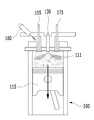
FIG. 1 is a conceptual diagram showing the construction of an engine system equipped with a gasoline-diesel combined combustion engine according to an embodiment of the present invention.
2 is a perspective view illustrating a cylinder of a gasoline-diesel combined combustion engine according to an embodiment of the present invention.
3 is a perspective view illustrating a cylinder head of a gasoline-diesel combined combustion engine according to an embodiment of the present invention.
4 is a cross-sectional view taken along line AA 'of FIG.
5 is a cross-sectional view taken along line BB 'of FIG.
6 is a cross-sectional view taken along line CC 'of FIG.
7 is a plan view showing the structure of an intake pipe and an exhaust pipe according to an embodiment of the present invention.
8 is a side view showing the structure of an intake pipe and an exhaust pipe according to an embodiment of the present invention.
9A to 9D are views for explaining the operation of the gasoline-diesel combined combustion engine according to the embodiment of the present invention.
첨부한 도면을 참고로 하여 본 발명의 실시예에 대하여 본 발명이 속하는 기술 분야에서 통상의 지식을 가진 자가 용이하게 실시할 수 있도록 상세히 설명한다. 그러나 본 발명은 여러 가지 상이한 형태로 구현될 수 있으며 여기에서 설명하는 실시예에 한정되지 않는다.BRIEF DESCRIPTION OF THE DRAWINGS The above and other features and advantages of the present invention will become more apparent by describing in detail exemplary embodiments thereof with reference to the attached drawings in which: FIG. The present invention may, however, be embodied in many different forms and should not be construed as limited to the embodiments set forth herein.
본 발명을 명확하게 설명하기 위해서 설명과 관계없는 부분은 생략하였으며, 명세서 전체를 통하여 동일 또는 유사한 구성요소에 대해서는 동일한 참조 부호를 붙이도록 한다.In order to clearly illustrate the present invention, parts not related to the description are omitted, and the same or similar components are denoted by the same reference numerals throughout the specification.
또한, 도면에서 나타난 각 구성의 크기 및 두께는 설명의 편의를 위해 임의로 나타내었으므로, 본 발명이 반드시 도면에 도시된 바에 한정되지 않으며, 여러 부분 및 영역을 명확하게 표현하기 위하여 두께를 확대하여 나타내었다.It is to be understood that both the foregoing general description and the following detailed description of the present invention are exemplary and explanatory and are intended to provide further explanation of the invention as claimed. .
이하에서는 본 발명의 실시예에 의한 가솔린-디젤 혼합 연소 엔진에 대하여 첨부된 도면을 참조하여 상세하게 설명한다.Hereinafter, a gasoline-diesel mixed combustion engine according to an embodiment of the present invention will be described in detail with reference to the accompanying drawings.
도 1은 본 발명의 실시예에 따른 가솔린-디젤 복합 연소 엔진이 구비된 엔진 시스템의 구성을 도시한 개념도이다. 도 2는 본 발명의 실시예에 따른 가솔린-디젤 복합 연소 엔진의 실린더를 도시한 개념도이다.FIG. 1 is a conceptual diagram showing the construction of an engine system equipped with a gasoline-diesel combined combustion engine according to an embodiment of the present invention. 2 is a conceptual diagram showing a cylinder of a gasoline-diesel combined combustion engine according to an embodiment of the present invention.
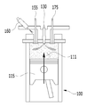
도 1에 도시된 바와 같이, 본 발명의 실시예에 의한 가솔린-디젤 복합 연소 엔진의 실린더(100)는 연료의 연소에 의해 동력을 발생시키는 연소실을 포함한다.As shown in FIG. 1, a
상기 실린더(100)는 가솔린 및 디젤 연료의 연소에 의해 동력을 발생시키는 연소실이 형성되는 실린더 몸체(110), 및 상기 실린더 몸체(110)의 상부를 덮는 실린더 헤드(120)를 포함한다.The
상기 실린더 몸체(110)는 대략 원통 형상으로 내부에 연소실이 형성되고 상부는 개구된다. 상기 실린더 헤드(120)는 개구된 실린더 몸체(110)의 상부를 덮는다. The
상기 실린더(100)에는 상기 연소실 내부로 디젤 연료를 분사하는 디젤 인젝터(130)와, 가솔린 연료를 분사하는 가솔린 인젝터(160)가 각각 장착된다.The
또한, 상기 실린더(100)에는 상기 연소실 내부로 분사된 가솔린 연료와 디젤 연료의 혼합 연료를 점화시키는 스파크 플러그(140)가 장착된다.In addition, the
이하에서는, 본 발명의 실시예에 따른 실린더의 구조에 대해 구체적으로 설명하도록 한다.Hereinafter, the structure of the cylinder according to the embodiment of the present invention will be described in detail.
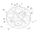
도 3은 본 발명의 실시예에 따른 가솔린-디젤 복합 연소 엔진의 실린더 헤드(120)를 도시한 개념도이다. 도 3은 상기 실린더 헤드(120)를 아래쪽에서 바라본 형상을 도시한 것이다.3 is a conceptual diagram showing a
도 4는 도 3의 A-A' 라인에 대한 단면도이다. 도 5는 도 3의 B-B' 라인에 대한 단면도이다. 그리고 도 6은 도 3의 C-C' 라인에 대한 단면도이다.4 is a cross-sectional view taken along line A-A 'of FIG. 5 is a cross-sectional view taken along the line B-B 'of FIG. And FIG. 6 is a cross-sectional view taken along line C-C 'of FIG.
도 3 내지 도 6에 도시된 바와 같이, 상기 실린더 헤드(120)는 상기 실린더 몸체(110)의 상부를 덮도록 대략 원판 형상으로 형성된다. 상기 실린더 헤드(120)의 하면은 한 쌍의 경사부(121)와, 상기 한 쌍의 경사부(121)가 맞닿는 모서리부(123)를 포함한다. 상기 한 쌍의 경사부(121)와 상기 모서리부(123)가 협력하여 상기 실린더 헤드(120)는 펜트 루프(pent roof) 형상을 형성한다.3 to 6, the
상기 한 쌍의 경사부(121)의 일측에는 한 쌍의 흡기 포트(125)가 형성되고, 상기 한 쌍의 경사부(121)의 타측에는 한 쌍의 배기 포트(127)가 형성된다. 즉, 상기 한 쌍의 흡기 포트(125)와 상기 한 쌍의 배기 포트(127)는 상기 모서리부(123)를 중심으로 서로 대칭되는 위치에 형성된다.A pair of
상기 실린더 헤드(120)의 중앙, 구체적으로, 상기 모서리부(123)의 중앙에는 디젤 연료를 상기 연소실 내부로 분사하는 디젤 인젝터(130)가 배치된다.A
상기 디젤 인젝터(130의 양측에는 한 쌍의 스파크 플러그(140)가 배치된다. 이때, 상기 한 쌍의 스파크 플러그(140)는 상기 디젤 인젝터(130를 중심으로 서로 대칭되는 위치에 배치되는 것이 바람직하다. 상기 스파크 플러그(140)는 상기 연소실 내로 유입된 가솔린과 디젤의 혼합 연료를 점화시킨다. A pair of
상기 스파크 플러그(140)가 상기 디젤 인젝터(130를 중심으로 서로 대칭되는 위치에 배치됨으로써, 상기 스파크 플러그(140)를 통해 발생한 화염이 전체 혼합 연료로 전파되는 거리(이하, '화염 전파 거리'라 함)를 최소화할 수 있다. The distance by which the flame generated through the
이와 같이, 화염 전파 거리가 최소화되면, 상기 스파크 플러그(140)를 통해 발생한 화염에 의해 상기 실린더 헤드(120)의 하면을 가열하는 quenching 효과가 감소하고, 이로 인해 노킹(knocking)이 발생하는 것을 방지할 수 있다.As described above, when the flame propagation distance is minimized, the quenching effect of heating the lower surface of the
상기 흡기 포트(125)에는 흡기 매니폴드(10)를 통해 신기를 공급하는 흡기관(150)이 연결된다. 상기 배기 포트(127)에는 상기 연소실에서 발생한 배기 가스를 배출하는 배기관(170)이 연결된다. 연소실에서 발생한 배기 가스는 상기 배기 포트(127)과 상기 배기관(170)을 통과하고 배기 매니폴드(20)를 통해 외부로 배출된다.The
그리고 상기 흡기관(150)에는 상기 연소실 내부로 가솔린 연료를 공급하기 위한 가솔린 인젝터(160)가 구비된다. 상기 가솔린 인젝터(160)는 공기와 가솔린 연료가 혼합된 후 상기 엔진의 연소실에 분사되는 가솔린 다중 분사 인젝터(MPI: multi point injector)일 수 있다. 또는, 상기 가솔린 인젝터(160)는 가솔린 연료가 상기 엔진의 연소실에 직접 분사되는 가솔린 직접 분사 인젝터(GDI: gasoline direct injector)일 수도 있다.The
상기 흡기관(150)에는 상기 흡기 포트(125)를 선택적으로 개폐하는 흡기 밸브(155)가 장착된다. 이때, 상기 가솔린 인젝터(160)는 상기 흡기 밸브(155)를 향하도록 장착되는 것이 바람직하다. 즉, 상기 가솔린 인젝터(160)는 상기 흡기관(150)에 장착되어 상기 흡기 포트(125)에 근접한 위치에 장착된다.The
이와 같이, 상기 가솔린 인젝터(160)가 상기 흡기 포트(125)에 근접한 위치에 장착됨으로써, 상기 가솔린 인젝터(160)에서 분사되는 공기와 연료가 폭발 행정을 통해 가열된 상기 흡기 밸브(155)를 냉각시켜 노킹이 발생하는 것을 방지할 수 있다.The
이하에서는, 상기 흡기관(150)과 배기관(170)의 구조에 대해 구체적으로 설명한다.Hereinafter, the structure of the
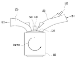
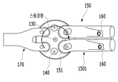
도 7은 본 발명의 실시예에 따른 흡기관 및 배기관의 구성을 도시한 평면도이다. 도 8은 본 발명의 실시예에 따른 흡기관 및 배기관의 구성을 도시한 측면도이다.7 is a plan view showing the structure of an intake pipe and an exhaust pipe according to an embodiment of the present invention. 8 is a side view showing the structure of an intake pipe and an exhaust pipe according to an embodiment of the present invention.
도 7 및 도 8에 도시된 바와 같이, 상기 한 쌍의 흡기관은 제1 흡기관과 제2 흡기관을 포함한다. 상기 제1 흡기관과 제2 흡기관은 상기 연소실 내에서 주로 텀블 방향 유동이 발생하도록 형성된다.As shown in Figs. 7 and 8, the pair of intake pipes includes a first intake pipe and a second intake pipe. The first intake pipe and the second intake pipe are formed to generate a tumble flow mainly in the combustion chamber.
도 7에 도시된 바와 같이, 상기 제1 흡기관(150)은 측면에서는 상기 실린더 헤드(120)의 위쪽 방향, 및 상기 배기 포트(127)의 반대 방향으로 일정 각도 기울어지도록 형성된다. 또한, 도 8에 도시된 바와 같이, 상기 제1 흡기관(150)은 평면에서는 상기 배기 포트(127)의 반대 쪽으로 직선 방향으로 연장되도록 형성된다. 7, the
이와 같이, 상기 제1 흡기관(150)이 측면에서는 상기 실린더 헤드(120)의 위쪽 방향, 및 상기 배기 포트(127)의 반대 방향으로 기울어지도록 형성되고, 평면에서는 상기 배기 포트(127)의 반대 방향으로 직선으로 연장되기 때문에, 상기 제1 흡기관(150)을 통해 유입되는 공기와 가솔린 연료는 텀블 방향의 유동을 형성한다.As described above, the
도 7에 도시된 바와 같이, 상기 제2 흡기관(150')은 측면에서는 상기 실린더 헤드(120)의 위쪽 방향, 및 상기 배기 포트(127)의 반대 방향으로 일정 각도 기울어지도록 형성된다. 또한, 도 8에 도시된 바와 같이, 상기 제2 흡기관(150')은 평면에서는 상기 배기 포트(127)의 반대 쪽으로 직선 방향으로 연장되도록 형성된다. 이때, 상기 흡기 포트(150)와 연결되는 상기 제2 흡기관(150')의 단부(151)는 상기 디젤 인젝터(130)로부터 상기 실린더 헤드(120)의 중심으로부터 반경 방향 바깥쪽으로 일정 각도(a) 기울어지도록 형성된다.7, the second intake pipe 150 'is formed to be inclined at a predetermined angle to the upper side of the
상기 단부(151)가 디젤 인젝터(130)로부터 상기 실린더 헤드(120)의 중심으로부터 반경 방향 바깥쪽으로 일정 각도 기울어지도록 형성됨으로써, 상기 제2 흡기관(150')을 통해 유입되는 공기와 가솔린 연료가 상기 연소실 내에서 스월 방향의 유동이 발생한다.The
즉, 상기 제1 흡기관(150)을 통해 유입되는 공기와 연료가 거의 텀블 방향의 유동만 발생되고, 상기 제2 흡기관(150')을 통해 유입되는 공기와 연료는 거의 대부분 텀블 방향 유동이 발생하지만, 상기 단부(151)에 의해 약간의 스월 방향 유동이 발생한다.That is, only the air flowing through the
가솔린-디젤 혼합 연소 엔진의 경우, 저부하 및 중부하 영역은 가솔린과 디젤 연료의 혼합 연소에 의한 혼합 연소 영역이고, 고부하 영역은 가솔린 단일 연료에 의한 가솔린 연소 영역이다.In the case of a gasoline-diesel mixed-combustion engine, the low-load and heavy-load regions are the mixed combustion region by the mixture combustion of gasoline and diesel fuel, and the high-load region is the gasoline combustion region by the gasoline single fuel.
이와 같은, 혼합 연소 엔진의 경우, 혼합 연소 영역에서는 스월비와 충진 효율을 최적화하는 것이 중요하고, 가솔린 연소 영역에서는 텀블비와 충진 효율을 최적화하는 것이 중요하다. 즉, 혼합 연소 엔진은 스월비(Rs), 텀블비(Rt), 및 충진 효율(Cf)을 모두 최적화할 수 있는 구성이 매우 중요하다.In such a mixed combustion engine, it is important to optimize the swirl ratio and the filling efficiency in the mixed combustion region, and it is important to optimize the tumble ratio and the filling efficiency in the gasoline combustion region. That is, a configuration in which the mixed combustion engine can optimize both the swirl ratio (Rs), the tumble ratio (Rt), and the filling efficiency (Cf) is very important.
여기서, 스월비(Rs)는 스월 방향 유동에 의해 발생하는 토크를 의미하고, 텀블비(Rt)는 텀블 방향 유동에 의해 발생하는 토크를 의미하며, 충진 효율(Cf)은 흡기와 배기의 기준 차압에 의해 유입되는 공기량을 의미한다.Here, the swirl ratio Rs refers to the torque generated by the swirl flow, the tumble ratio Rt refers to the torque generated by the tumble direction flow, and the filling efficiency Cf refers to the reference differential pressure The amount of air flowing into the combustion chamber.
따라서, 혼합 연소 엔진에서 흡기 포트를 본 발명에서 개시한 바와 같이 설계함으로써, 스월비(Rs), 텀블비(Rt), 및 충진 효율(Cf)을 모두 최적화할 수 있다.Therefore, by designing the intake port in the mixed combustion engine as described in the present invention, it is possible to optimize both the swash ratio Rs, the tumble ratio Rt, and the filling efficiency Cf.
이하에서는, 상기한 바와 같은 본 발명의 가솔린-디젤 혼합 연소 엔진의 동작에 대해 첨부된 도면을 참조하여 상세하게 설명한다.Hereinafter, the operation of the gasoline-diesel mixed combustion engine of the present invention as described above will be described in detail with reference to the accompanying drawings.
도 9a 내지 도 9d는 본 발명의 실시예에 따른 가솔린-디젤 복합 연소 엔진의 동작을 설명하기 위한 도면이다.9A to 9D are views for explaining the operation of the gasoline-diesel combined combustion engine according to the embodiment of the present invention.
도 9a를 참조하면, 흡입 행정 중에 상기 흡기관(150)에 구비된 흡기 밸브(155)가 상기 흡기 포트(125)를 개방하고, 흡기 매니폴드(10)를 통해 유입되는 공기와 상기 가솔린 인젝터(160)를 통해 분사되는 가솔린 연료가 예혼합되어 상기 연소실 내부로 분사된다.9A, an
이때, 상기 가솔린 인젝터(160)는 상기 흡기 밸브(155)를 향하도록 장착되기 때문에, 상기 가솔린 인젝터(160)에 의해 분사되는 공기와 가솔린 연료가 폭발 행정 중에 가열된 흡기 밸브(155)를 냉각시키고, 이로 인해 연소 과정에서 발생하는 노킹을 억제할 수 있다.At this time, since the
도 9b를 참조하면, 압축 행정 중에 피스톤이 상측으로 이동하면서 예혼합된 가솔린 연료를 압축하기 시작하고, 상기 디젤 인젝터(130)를 통해 디젤 연료가 연소실 내부로 분사된다. 상기 디젤 인젝터(130)에 의해 분사되는 디젤 연료는 가솔린 연료의 착화를 제어하기 위한 용도로 사용될 수 있다.Referring to FIG. 9B, the piston starts to compress premixed gasoline fuel as the piston moves upward during the compression stroke, and diesel fuel is injected into the combustion chamber through the
도 9c를 참조하면, 상기 피스톤이 상측으로 이동하면서 분사된 디젤 연료를 압축하여 착화가 이루어진다. 필요에 따라서는 상기 스파크 플러그(140)를 통해 점화가 이루어진다. 이때, 상기 스파크 플러그(140)는 상기 실린더 헤드(120)의 중앙에 배치되는 디젤 인젝터(130)를 중심으로 서로 대칭되는 위치에 장착되기 때문에, 상기 스파크 플러그(140)로부터 발생한 화염이 상기 연소실 내부의 전체 연료로 전달되는 화염 전파 거리가 최소화된다. Referring to FIG. 9C, ignition is performed by compressing the injected diesel fuel while the piston moves upward. If necessary, ignition is performed through the
도 9d를 참조하면, 가솔린-디젤이 혼합된 전체 연료가 점화되면서 혼합 연료가 폭발하고, 이때 발생한 동력으로 인해 상기 피스톤이 아래쪽으로 동력이 발생하게 된다. 그리고 상기 배기 밸브(175)가 개방되면서, 연소 과정에서 발생한 배기 가스는 배기 포트(127)를 통해 배기 매니폴드(20)로 배출된다.Referring to FIG. 9D, the fuel mixed with the gasoline-diesel is ignited, and the mixed fuel explodes, and the generated power causes the piston to generate power downward. The
이때, 상기 실린더 헤드(120)가 펜트 루프 형상으로 형성되기 때문에, 착화 행정과 폭발 행정을 통해 발생한 화염이 실린더 헤드(120)로 도달하는 거리가 멀기 때문에, 실린더 헤드(120)가 고온의 화염으로 인해 가열되는 것을 최소화할 수 있고, 이로 인해 노킹이 발생하는 것을 방지할 수 있다.At this time, since the
이상을 통해 본 발명의 바람직한 실시예에 대하여 설명하였지만, 본 발명은 이에 한정되는 것이 아니고 특허청구범위와 발명의 상세한 설명 및 첨부한 도면의 범위 안에서 여러 가지로 변형하여 실시하는 것이 가능하고 이 또한 본 발명의 범위에 속하는 것은 당연하다.While the present invention has been particularly shown and described with reference to exemplary embodiments thereof, it is to be understood that the invention is not limited to the disclosed exemplary embodiments, but, on the contrary, And it goes without saying that the invention belongs to the scope of the invention.
10: 흡기 매니폴드
20: 배기 매니폴드
100: 실린더
110: 실린더 몸체
120: 실린더 헤드
121: 경사부
123: 모서리부
125: 흡기 포트
127: 배기 포트
130: 디젤 인젝터
140: 스파크 플러그
150: 흡기관
155: 흡기 밸브
160: 가솔린 인젝터
170: 배기관
175: 배기 밸브10: Intake manifold
20: Exhaust manifold
100: Cylinder
110: Cylinder body
120: cylinder head
121:
123:
125: Intake port
127: exhaust port
130: Diesel injector
140: Spark plug
150: intake pipe
155: intake valve
160: Gasoline injector
170: Exhaust pipe
175: Exhaust valve
Claims (7)
상기 실린더 헤드에 형성되는 한 쌍의 흡기 포트;
상기 실린더 헤드에 형성되고 상기 한 쌍의 흡기 포트와 대칭되는 위치에 형성되는 한 쌍의 배기 포트;
상기 실린더 헤드의 중앙에 장착되고 상기 연소실로 디젤 연료를 분사하는 디젤 인젝터;
상기 실린더 헤드에 구비되고 상기 디젤 인젝터의 양측에 배치되는 스파크 플러그;
상기 흡기 포트에 구비되어 상기 연소실로 선택적으로 공기를 공급하는 제1 흡기관과 제2 흡기관;
상기 배기 포트에 구비되어 상기 연소실에서 발생한 배기를 배출하는 배기관;
상기 흡기관에 구비되어 상기 흡기 포트를 선택적으로 개폐하는 흡기 밸브; 및
상기 흡기관에 구비되어 상기 연소실로 가솔린 연료를 공급하는 가솔린 인젝터;
를 포함하고,
상기 제1 흡기관은 측면에서는 상기 실린더 헤드의 위쪽 방향, 및 상기 배기 포트의 반대 방향으로 일정 각도 기울어지도록 형성됨과 동시에 평면에서는 상기 배기 포트의 반대 쪽으로 직선 방향으로 연장되도록 형성되고,
상기 제2 흡기관은 측면에서는 상기 실린더 헤드의 위쪽 방향, 및 상기 배기 포트의 반대 방향으로 일정 각도 기울어지도록 형성됨과 동시에 평면에서는 상기 배기 포트의 반대 쪽으로 직선 방향으로 연장되도록 형성되고, 상기 흡기 포트와 연결되는 제2 흡기관의 단부는 상기 디젤 인젝터(130)로부터 상기 실린더 헤드(120)의 중심으로부터 반경 방향 바깥쪽으로 일정 각도 기울어지도록 형성되는 가솔린-디젤 혼합 연소 엔진.A cylinder including a cylinder body formed with a combustion chamber for generating power by combustion of gasoline and diesel fuel, and a cylinder head covering an upper portion of the cylinder body;
A pair of intake ports formed in the cylinder head;
A pair of exhaust ports formed in the cylinder head and formed at positions symmetrical with the pair of intake ports;
A diesel injector mounted at the center of the cylinder head and injecting diesel fuel into the combustion chamber;
A spark plug provided on the cylinder head and disposed on both sides of the diesel injector;
A first intake pipe and a second intake pipe provided in the intake port to selectively supply air to the combustion chamber;
An exhaust pipe provided in the exhaust port and discharging exhaust gas generated in the combustion chamber;
An intake valve provided on the intake pipe for selectively opening and closing the intake port; And
A gasoline injector provided in the intake pipe for supplying gasoline fuel to the combustion chamber;
Lt; / RTI >
Wherein the first intake pipe is formed so as to be inclined at a predetermined angle in an upward direction of the cylinder head and in a direction opposite to the exhaust port on a side surface and extends in a linear direction opposite to the exhaust port in a plane,
Wherein the second intake pipe is formed so as to be inclined at a predetermined angle in an upward direction of the cylinder head and in a direction opposite to the exhaust port and extends in a linear direction opposite to the exhaust port in a plane, The end of the second intake pipe connected is formed so as to be inclined from the diesel injector (130) at a predetermined angle in a radially outward direction from the center of the cylinder head (120).
상기 디젤 인젝터는 상기 실린더 헤드의 중앙에 배치되는 가솔린-디젤 혼합 연소 엔진.The method according to claim 1,
Wherein the diesel injector is disposed in the center of the cylinder head.
상기 한 쌍의 스파크 플러그는
상기 디젤 인젝터를 중심으로 서로 대칭되는 위치에 배치되는 가솔린-디젤 혼합 연소 엔진.3. The method of claim 2,
The pair of spark plugs
And a gasoline-diesel mixed combustion engine disposed at a position symmetrical with respect to the diesel injector.
상기 실린더 헤드의 하면은
상기 흡기 포트와 상기 배기 포트가 각각 형성되는 한 쌍의 경사부;
상기 한 쌍의 경사부가 맞닿는 모서리부를 포함하고,
상기 경사부와 상기 모서리부가 협력하여 펜트 루프 형상을 형성하는 가솔린-디젤 혼합 연소 엔진.The method according to claim 1,
The lower surface of the cylinder head
A pair of inclined portions in which the intake port and the exhaust port are formed, respectively;
And a pair of inclined portions abutting against each other,
Wherein the inclined portion and the corner portion form a pent roof shape in cooperation with the gasoline-diesel mixed combustion engine.
상기 한 쌍의 흡기 포트와 상기 한 쌍의 배기 포트는 상기 한 쌍의 경사부에 각각 형성되는 가솔린-디젤 혼합 연소 엔진.The method according to claim 1,
Wherein the pair of intake ports and the pair of exhaust ports are formed in the pair of inclined portions, respectively.
상기 디젤 인젝터는 상기 모서리부의 중앙에 설치되는 가솔린-디젤 혼합 연소 엔진.The method according to claim 1,
Wherein the diesel injector is installed at the center of the corner portion.
상기 가솔린 인젝터는
상기 흡기 밸브를 향하는 방향으로 장착되는 가솔린-디젤 혼합 연소 엔진.The method according to claim 1,
The gasoline injector
And is mounted in a direction toward the intake valve.
Priority Applications (4)
| Application Number | Priority Date | Filing Date | Title |
|---|---|---|---|
| KR1020150178660A KR20170070750A (en) | 2015-12-14 | 2015-12-14 | Gasolin-diesel complex combustion engine |
| US15/210,186 US20170167456A1 (en) | 2015-12-14 | 2016-07-14 | Gasoline-diesel complex combustion engine |
| CN201610648809.4A CN106870115A (en) | 2015-12-14 | 2016-08-09 | Gasoline, diesel composite internal combustion engine |
| DE102016118591.4A DE102016118591A1 (en) | 2015-12-14 | 2016-09-30 | PETROL DIESEL ENGINE COMBINATION OF BURNS |
Applications Claiming Priority (1)
| Application Number | Priority Date | Filing Date | Title |
|---|---|---|---|
| KR1020150178660A KR20170070750A (en) | 2015-12-14 | 2015-12-14 | Gasolin-diesel complex combustion engine |
Publications (1)
| Publication Number | Publication Date |
|---|---|
| KR20170070750A true KR20170070750A (en) | 2017-06-22 |
Family
ID=58773602
Family Applications (1)
| Application Number | Title | Priority Date | Filing Date |
|---|---|---|---|
| KR1020150178660A Ceased KR20170070750A (en) | 2015-12-14 | 2015-12-14 | Gasolin-diesel complex combustion engine |
Country Status (4)
| Country | Link |
|---|---|
| US (1) | US20170167456A1 (en) |
| KR (1) | KR20170070750A (en) |
| CN (1) | CN106870115A (en) |
| DE (1) | DE102016118591A1 (en) |
Families Citing this family (6)
| Publication number | Priority date | Publication date | Assignee | Title |
|---|---|---|---|---|
| JP2019019707A (en) * | 2017-07-13 | 2019-02-07 | 愛三工業株式会社 | Fuel supply system for internal combustion engine |
| CN108506122A (en) * | 2018-05-12 | 2018-09-07 | 陈向红 | High compression ratio ignition internal combustion engine and its working method |
| DE102018207999B4 (en) * | 2018-05-22 | 2022-02-03 | Bayerische Motoren Werke Aktiengesellschaft | Internal combustion engine for a motor vehicle, motor vehicle and method for operating such an internal combustion engine |
| CN110206629B (en) * | 2019-04-25 | 2020-07-14 | 清华大学 | Active pre-chamber ignition system and combustion system for hybrid engine |
| CN115419502A (en) * | 2022-10-19 | 2022-12-02 | 天津大学 | Engine combustion system with combined air inlet channel and combustion chamber in cooperation |
| EP4733570A1 (en) * | 2024-10-22 | 2026-04-29 | Volvo Truck Corporation | Ignition system |
Family Cites Families (3)
| Publication number | Priority date | Publication date | Assignee | Title |
|---|---|---|---|---|
| KR0178660B1 (en) | 1996-09-18 | 1999-04-01 | 정몽규 | Seat belt webbing restraint on vehicle |
| JP4386781B2 (en) * | 2004-03-31 | 2009-12-16 | 大阪瓦斯株式会社 | engine |
| KR101745005B1 (en) * | 2011-10-07 | 2017-06-09 | 현대자동차주식회사 | Diesel - Gasoline Complex Engine |
-
2015
- 2015-12-14 KR KR1020150178660A patent/KR20170070750A/en not_active Ceased
-
2016
- 2016-07-14 US US15/210,186 patent/US20170167456A1/en not_active Abandoned
- 2016-08-09 CN CN201610648809.4A patent/CN106870115A/en active Pending
- 2016-09-30 DE DE102016118591.4A patent/DE102016118591A1/en not_active Withdrawn
Also Published As
| Publication number | Publication date |
|---|---|
| CN106870115A (en) | 2017-06-20 |
| US20170167456A1 (en) | 2017-06-15 |
| DE102016118591A1 (en) | 2017-06-14 |
Similar Documents
| Publication | Publication Date | Title |
|---|---|---|
| CN105658928B (en) | Divided chamber gas engine | |
| US8910612B2 (en) | Pre-chamber jet igniter and engine including combustion chamber employing the same | |
| US10968814B2 (en) | Internal combustion engine for a motor vehicle | |
| KR101745005B1 (en) | Diesel - Gasoline Complex Engine | |
| US6928997B2 (en) | Direct injection engine | |
| US10718258B2 (en) | Spark-ignited direct-injection engine combustion systems | |
| JP2009108778A (en) | Fuel injection apparatus for compression ignition type internal combustion engine | |
| JP6337877B2 (en) | Combustion chamber structure of internal combustion engine | |
| US6095114A (en) | Gasoline direct-injection engine | |
| US4491104A (en) | Torch ignition type internal combustion engine | |
| CN112443390A (en) | Ignition arrangement and internal combustion engine | |
| US20170167456A1 (en) | Gasoline-diesel complex combustion engine | |
| US6701883B2 (en) | Cylinder head for use on a spark-ignition internal combustion engine and such spark-ignition internal combustion engine | |
| CN100419231C (en) | Gas internal combustion engine with premixed precombustion in-cylinder injection | |
| JPH06117250A (en) | 2-point ignition engine | |
| JP4164587B2 (en) | Internal combustion engine | |
| JP4420212B2 (en) | 2-point ignition internal combustion engine | |
| KR20190047314A (en) | Cylinder structure of diesel engine | |
| JP2002106353A (en) | Spark ignition direct injection engine | |
| KR100303979B1 (en) | 3-valve gasoline engine | |
| JP3468055B2 (en) | Lean-burn internal combustion engine | |
| JP2011214557A (en) | Cylinder injection type spark ignition internal combustion engine | |
| KR20090063476A (en) | Piston Heads for Gasoline Direct Injection Engines | |
| WO2024201933A1 (en) | Internal combustion engine with auxiliary combustion chamber | |
| KR100203507B1 (en) | Direct injection typed gasoline engine |
Legal Events
| Date | Code | Title | Description |
|---|---|---|---|
| A201 | Request for examination | ||
| PA0109 | Patent application |
Patent event code: PA01091R01D Comment text: Patent Application Patent event date: 20151214 |
|
| PA0201 | Request for examination | ||
| E902 | Notification of reason for refusal | ||
| PE0902 | Notice of grounds for rejection |
Comment text: Notification of reason for refusal Patent event date: 20170218 Patent event code: PE09021S01D |
|
| PG1501 | Laying open of application | ||
| E601 | Decision to refuse application | ||
| PE0601 | Decision on rejection of patent |
Patent event date: 20170801 Comment text: Decision to Refuse Application Patent event code: PE06012S01D Patent event date: 20170218 Comment text: Notification of reason for refusal Patent event code: PE06011S01I |