US648024A - Rotary engine. - Google Patents
Rotary engine. Download PDFInfo
- Publication number
- US648024A US648024A US70383899A US1899703838A US648024A US 648024 A US648024 A US 648024A US 70383899 A US70383899 A US 70383899A US 1899703838 A US1899703838 A US 1899703838A US 648024 A US648024 A US 648024A
- Authority
- US
- United States
- Prior art keywords
- cylinder
- sleeve
- shaft
- steam
- piston
- Prior art date
- Legal status (The legal status is an assumption and is not a legal conclusion. Google has not performed a legal analysis and makes no representation as to the accuracy of the status listed.)
- Expired - Lifetime
Links
- 230000002093 peripheral effect Effects 0.000 description 19
- 230000004323 axial length Effects 0.000 description 8
- 238000012856 packing Methods 0.000 description 7
- 238000004891 communication Methods 0.000 description 5
- 230000006854 communication Effects 0.000 description 5
- 230000006870 function Effects 0.000 description 3
- 230000002441 reversible effect Effects 0.000 description 3
- 238000010276 construction Methods 0.000 description 2
- 230000001627 detrimental effect Effects 0.000 description 2
- 229910001018 Cast iron Inorganic materials 0.000 description 1
- 108010002947 Connectin Proteins 0.000 description 1
- 102000004726 Connectin Human genes 0.000 description 1
- 230000003247 decreasing effect Effects 0.000 description 1
- 230000000694 effects Effects 0.000 description 1
- 239000012530 fluid Substances 0.000 description 1
- 239000000463 material Substances 0.000 description 1
- 238000005192 partition Methods 0.000 description 1
- 108010085990 projectin Proteins 0.000 description 1
- 230000000284 resting effect Effects 0.000 description 1
- 239000007787 solid Substances 0.000 description 1
- 238000000638 solvent extraction Methods 0.000 description 1
- 230000003313 weakening effect Effects 0.000 description 1
Images


Classifications
-
- B—PERFORMING OPERATIONS; TRANSPORTING
- B24—GRINDING; POLISHING
- B24B—MACHINES, DEVICES, OR PROCESSES FOR GRINDING OR POLISHING; DRESSING OR CONDITIONING OF ABRADING SURFACES; FEEDING OF GRINDING, POLISHING, OR LAPPING AGENTS
- B24B55/00—Safety devices for grinding or polishing machines; Accessories fitted to grinding or polishing machines for keeping tools or parts of the machine in good working condition
-
- F—MECHANICAL ENGINEERING; LIGHTING; HEATING; WEAPONS; BLASTING
- F01—MACHINES OR ENGINES IN GENERAL; ENGINE PLANTS IN GENERAL; STEAM ENGINES
- F01C—ROTARY-PISTON OR OSCILLATING-PISTON MACHINES OR ENGINES
- F01C1/00—Rotary-piston machines or engines
- F01C1/30—Rotary-piston machines or engines having the characteristics covered by two or more groups F01C1/02, F01C1/08, F01C1/22, F01C1/24 or having the characteristics covered by one of these groups together with some other type of movement between co-operating members
- F01C1/34—Rotary-piston machines or engines having the characteristics covered by two or more groups F01C1/02, F01C1/08, F01C1/22, F01C1/24 or having the characteristics covered by one of these groups together with some other type of movement between co-operating members having the movement defined in group F01C1/08 or F01C1/22 and relative reciprocation between the co-operating members
- F01C1/344—Rotary-piston machines or engines having the characteristics covered by two or more groups F01C1/02, F01C1/08, F01C1/22, F01C1/24 or having the characteristics covered by one of these groups together with some other type of movement between co-operating members having the movement defined in group F01C1/08 or F01C1/22 and relative reciprocation between the co-operating members with vanes reciprocating with respect to the inner member
Definitions
- the object of my invention generally speaking, is to provide a more simple,'less eXpensive, and more efficient engine thanhas been known heretofore.
- Myinvention has for its object particularly to provide an engine that will have the steam acting upon the piston thereof withequal leverage throughout approximately its complete cycle or. stroke, the steam-pressure at the same time to be adapted to act only upon the piston with abutment upon all the interior faces of the piston-chamber without in anyway or at any time exerting What is known as side load upon the shaft and which is so evident in and detrimental to the efficiency ofrotary engines in general.
- the invention may be said,broadlyspeaking, to consist in constructing a rotary engine with the interior of the cylinder thereof separated from' the surface. of the shaft which passes therethrough, thus constituting an annular chamber.
- the piston revolves within this chamber, and I form an abutment-chamber in communication with the after face of the piston during approximately the complete stroke thereof 'whatever may be the direction of its revolution.
- my improved engine comprises an annular chamber formed by a cylinder having its ends closed and bored to allow the shaft to extend therethrough and a divided stationary sleeve inclosing the por-' tion of the surface of said shaft within the cylinder, except for a small portion to which the piston is rigidly connected, the piston completely bisecting said annular chamber.
- I form an abutment chamber by mounting a rotary sleeve therein in a position to intersect said annular chamber and having a portion cut away to accom modate the piston in its revolution.
- I locate acore Within this sleeve, with the portion thereof that intersects the annular chamber milled away on the periphractic line of said chamber, while the surface of the core and the interior of that portion of the casing inclosing said rotary sleeve are correspondingly grooved from one milled edge of said core around said core and the interior of the casing to a point a distance from the other milled edge slightly greater than the width of the opening in said rotary sleeve, means being provided to cause the sleeve to rotate inunison with the revolution of the piston, a steam-cushion being adapted to act as a countervailing pressure upon said rotary sleeve to that exerted upon the opposite side thereof by the steam-pressure either direct or in expansion,
- Fig. 3 a detail view illustrating in plan view the operative connection between the. governor-valve and its actuating-gear;
- Fig. 4 an enlarged transverse sectional View of one of my improved peripheral packingrings Fig. 5, a transverse vertical sectional View of the engine, taken on line 5 5, Fig.1, and illustrating the parts in position to first admit steam to the annular cylindrical chamber;
- Fig. 6, a similar view,but illustrating the parts in position to cut off the steam when theengineworks undermaximumload.
- Fig.7 is also a similar view, but illustrating in full lines and dotted lines, respectively, the parts in the positions they assume at the com mencement and completion of the interval that I designate the dead-point in the cycle of the revolution of the piston.
- Fig. 8 is a similar View, but taken on line 8 8, Fig. 1, and illustrating the combined throttle-valve and reversing-gear, the steam-chest, the automatic cut-off valve and governor-valve, and the steam-cushion.
- Fig. 9 is a horizontal sectional view taken on line 9, Fig. 1, and illustrating my improved combined throttle and reversing-gear.
- Fig. 10 is a transverse vertical sectional view looking toward the interior of the engine, taken on line 10 10, Fig.
- Fig. 11 is a similar View, but looking in the opposite direction and illustrating the interior of the caps that inclose the steam-chest and adjacent end of the rotary abutment; and Fig. 12 is a detail elevation, partly in section, of the front side of the piston as'it travels ahead. The direction of going ahead of the engine is indicated by plain arrows, and the direction of flow of the steam is indicated by feathered arrows.
- the casing of my improved engine is of a form to present a main chamber 5 and an adjoining snbchamber 6, both extending from end to end of the casing,,the ends of the main chamber being closed by heads 7 7, cast in one with the casing and perforated to allow a shaft 8 to extend therethrough.
- a pinion 45 is mounted rigidly upon each end of the shaft outside of the casing, and between said pinions and the faces of the cylinder-heads I locate a pair of cups 150 and 151, with their rims in steam-tight contact with the cylinderheads, the adjacent portions of the cylinderheads and said rims being ground to from said steam-tight joint.
- the casing is transverselydivided into two parts, which are secured together by a series of screw bolts 9, taking through flanges formed upon the adjoining edges thereof.
- each half of the main chamber 5 and concentrically thereof a sleeve length 10 iscast, the two lengths conjointly inclosing the complete surface of the portion of the shaft within the cylinder (except for a small space midway of the length of said cylinder) and forming a partition that establishes between it and the inside face of said main chamber 5 an annular chamber 11, constituting the cylinder of the engine.
- the piston is in the form of a bar of a length and breadth to present a steam-bearing surface equal and conforming to the transverse area of said annular chamber 11 and of a thickness sufficient to accommodate a series of packing-strips.
- This piston is formed in tegrally with the periphery of the said disk 12, and one side thereof is of convex form, as at 61, and this disk is in turn secured rigidly to the shaft by means of a hub 62, weighted, as at (33, on the side thereof opposite to that at which the piston is mounted in order to counterbalance said piston, the portions of the weighted part of said hub on each side of the disk being preferably of conical form to enable an extended connection therebetween' and the shaft to be effected without weakening the connection between the sleeve portion 10 and the cylinder and at the same time enable the material of the cylinder-heads to he of suflicient thickness to allow the before-mentioned steam supply and exhaust ports Ga and 110, respectively,
- a steam-tight joint is eifected between the edges of the piston and the peripheral wall of the chamber 11, the interior faces of the cylinder-heads 7 7; and the sleeve lengths '10 by means of a packingstrip 52, embedded in the radial outer edge of the piston, and a pair of rectangular strips 53, embedded in the ends and radial inner edge of the piston.
- These strips are caused to bear, respectively, upon the four walls of the annular chamber by means of a series of expansile coiled springs 54:, located in a series of sockets 55 in the piston edges and bearing outwardly upon said strips.
- a steam-tight joint is established between the abutting edge of each sleeve portion and the disk by a metallic ring 14 in a recess 15, extending completely around said edge and having a series of axial borings or sockets 16, in which a series of expansile coiled springs 17 are located and bear outwardly upon the adjacent face of the said ring 11 and cause it in turn to bear upon the adjacent side of the disk.
- the ends of the subchamber G are open on the vertical plane of the cylinder-heads 7 7,
- Thesleeve 21 isformed with an opening 51, extending the full length of the space between the cylinder-heads 7 7 and of a width to allow the piston to pass therethrough with its edges in close proximity to but out of frictional contact with the edges thereof during the revolution of the piston, as will be presently shown.
- the circumference of this sleeve, adjacent to each end thereof, is geartoothed, as. at 30, to intermesh with 'the before-mentioned pinion 45, with which said gear-toothed portion corresponds in circumference.
- a core extends from end to end of the interior of this sleeve 21 and has a circumferential groove 96 midway of its length and extending like the before-mentioned groove 95 from the annular chamberll to a point on a radial line with, the end of said groove 95.
- This core is constructed of a pair of core portions, secured by bolts 35 rigidly to the end of each of the caps 18 and 19, each core portion being divided into two pieces 36 and 37.
- Theouter ends of the-pieces 36 are formed to present circular shoulders 38, talc-- ing into recesses in the ends of the caps, and the ends ofthe pieces 37 that adjoin the pieces 36 are circum ferentially recessed to accom modate packing-rings carried by theinterior of the sleeve 21.
- These packin g-rin gs each consists of a flanged ring 40, secured by bolts 41 to the interior of the sleeve and havinga series of sockets 42 formed therein to receive andlocalize a series of expansile coiled springs 43, while a ring 44, preferably of cast-iron, lies intermediate said springs and the face of the adjacent core-pieces 36.
- the diameter of the core-pieces 36 exceeds that of the pieces 37, and the sleeve is cored'out adjacent to its ends to accommodate the packing-rings 44c and the greater diameter of pieces 36, and at the same time to provide a shoulder to assist the bolts 41 in affording an abutment for the springs 43.
- the core pieces 37 have the lower portions thereof that intersect the annular cylindrical chamber 11 milled away, as
- the steam is supplied to and exhausted from the cylinder 11 and the supply and exhaust automatically controlled as follows:
- the steam is fed to the steam-chest through a pipe 68 and thence passes through the port 64: to the cylinder 11.
- An automatic cut-off for said port 64 consists of a flanged valvular disk 69, cast in one with a short sleeve 77, mounted upon the shaft and connected thereto to rotate therewith, but free to slide axially thereof, by a slot 70 in said sleeve and a pin 71, carried rigidly by said shaftin a position to engage said slot.
- This disk is located in close proximity to the cylinder-head 7 in which it is countersunk, and has a series of openings 72, 73, 74, and of different areas, adapted to consecutivelycommunicate with said port 64. These openings extend, with intervals of connecting bridge pieces 7", for about one -half the circumference of said flanged disk. In constructing marine or other portable engines according to my invention a cut-off of this construction, or, under certain circumstances, with none other than the main port 72, will be found sufficient, as will be'clearly pointed out hereinafter.
- This automatic controller or governor consists of a segmental valve-plate 78, having ports 82, and a series of-valvular bridge portions 79, 80,
- This plate 78 is seated upon the disk 69-and formed in one I with a short sleeve 83,offset,as at 84, to fit over the sleeve 77 and the'shaft and having a diagonal slot 85.
- a collar 91 having two pairs of lugs 92, arranged diametrically opposite to one another, issecured rigidly upon the outer end of the spindle 87 by a set-screw 93.
- a pair of rods 94 are each pivotally connected to one of said pairs of lugs, and the other ends thereof are pivotally connected to a pair of governorballs .95, which are in turn pivotally connected by a pair'of rods 96 to the lugs 97 of a collar 98 similar to the collar 91, but rigidly mounted upon the shaft, while an expansile coiled spring 99 encircles the spindle 87 and bears between the collar 91 and the stuffingbox 90.
- the exhaust-port 100 from the cylinder is, as before mentioned, cut through the portion of the cylinder-head 7 inclosed by the exhaust-chamber cylinder-head 7 similarly to the steam-supply port 6% and effects a communication between the annular cylindrical which is recessed to accommodate it.
- the cup constitutes the exhaust-chamber
- the cap 46 like the cap 66, is formed with a bearing-sleeve for the shaft.
- Asegmental valve-plate 101 formed in one with a short sleeve 102, is secured rigidly through said sleeve upon the shaft within the cup 151 and in close contact with the cylinder-head 7, This plate is of a circumferential length to completely close the port 100 during a dead-point interval clearly pointed out in the description of the operation hereinafter.
- My improved combined throttle-valve and reversing-gear consists of a cylindrical chamber 105, having a horizontal valve-seat, a portion 106 whereof encircles and other portions 107 and 108 whereof separate the mouths of four ports 109,110, 112, and 113, respectively.
- the port 109 communicates with the steamsupply pipe'114
- the port 110 communicates with the steam-exhaust pipe 111
- the ports 112 and 113 communicate, respectively, through pipe 68 (before mentioned) with the stearmchest 6S and a pipe 116 with the exk haust-chamber 46.
- a valve in the form of a circular plate 115 Resting upon this'seat is a valve in the form of a circular plate 115,
- This valvular plate is mounted rigidly upon the lower end of a stem 119, extending upwardly through a short sleeve 121, formed concentrically of a cover and'provided with a stuffing box 122, the cover being screwed into the cylinder 105, while a handle 123 is mounted rigidly upon the upper end of the stem 119.
- stop-cocks 133 are provided with stop-cocks 133.
- the steam Upon starting the engine the steam will pass from the steamchest through port 64 into the portion of the annular cylinder 11 that is inclosed by the abutment-sleeve 21, as shown in Fig. 8.
- the steam will continue to be admitted to act directly upon the piston for from fifty-five degrees to approximately one hundred and eighty degrees of the revolution thereof, accordin to the resistance to or steam-pressure acting upon the engine, after which, excepting for a comparatively speaking diminutive dead-point, (the interval before mentioned,) the balance of the stroke will be under the power of expansion, as will be presently pointed out.
- the abutment-sleeve 21 will through the gears 45 and 30 be rotated in an opposite direction, and the steam will then be admitted between the after face of the piston and the adjacent portion of the abutment-sleeve intersecting the annular cylinder. It will not, however, abut upon this portion of the sleeve, but will find its way through groove 95, the opening 51 in the abutment-sleeve 21, and the groove 96 to the chamber 50, where abutment will take place, with the result that much greater force will be exerted upon the interior of the sleeve at that point.than upon the exterior of the portion thereof that intersects the annular cylinder.
- This interval is the deadpoint before mentioned and occurs between the time that the forward axial edge of the opening 51 (while the sleeve 21 is rotating in either. direction) leaves the vertical plane of the partitioning-sleeve and the time that the after axial edge reaches said vertical plane.
- the exhaust-control valve 102 incidentally closes the exhaust-port 100, which for the rest of the time is open, and the engine completes its cycle by its own momentum, the true function of this exhaust-valve being exerted as the engine reverses, but the incidental function just alluded to is of advantage to the engine for economical purposes, as it traps and retains in the cylinder of the engine a body of steam representing an energy that would otherwise be lost.
- the handle 123 should be moved to the position shown in chain-lines in Fig. 9, thus causing the recess 11-1 to register with both ports 110 and 113 and the V-groove to register with the port 112, thereby establishing a direct communication from the steam-supply pipe 144 through the ports 109 and 112 to what has constituted the exhaust chamber as the engine traveled ahead, but that now in reversal constitutes the steam-chest 46 and a direct com munication from the (under the prevailing conditions) exhaust-chamber (56 through port 113,recess 114,and port 110 to the exhaust-pipe 111.
- the flanged plate and segmental valvular plate constituting the automatically-variable outoff or governor can have the portions thereof with the ports therein cutaway. This, however, I consider would impair the efficiency of the governor to a certain extent. It is also obvious that by connecting the shaft of my engine to any suitable driving-gear, the engine will serve as a pump.
- a cylinder having a radial extension, a piston revoluble within said cylinder; a rotary abutment located within said radial extension, and consisting of a sleeve having an opening in its side of sufficient area to accommodate the piston in its revolution; a stationary core extending through said sleeve from end to end thereof and having a portion milled away on the periphractic line of the cylinder; means for causing said sleeve to rotate in an opposite direction to the piston, and a steam supply to and exhaust from said cylinder, for the purpose set forth.
- a cylinder having a radial extension with an interior peripheral groove; a piston revoluble within said cylinder; a rotary abutment located within said radial extension, and consisting of a sleeve having an opening in its side of sufficient area to accommodate the piston in its revolution, the said groove extendingfrom one line of junction of said cylinder and extension to a point distant'from the other line of juncture greater than the width of the opening in the side of the abutment; a stationary core extending through said sleeve from end to end thereof and having a portion milled away on the periphractic line of the cylinder and having a peripheral groove extending around the cylindrical portion from one milled edge to a point in the radial plane of the corresponding end of the first-mentioned groove; means for causing said sleeve to rotate in an opposite direction to the piston; and a steam supply to and exhaust from said cylinder, for the purpose set forth.
- a cylinder having a radial extension; a shaft extending through said cylinder from end to end thereof, a piston revoluble within said cylinder; a stationary partitioning sleeve inclosing approximately the complete portion of the shaft within said cylinder; means for connecting the piston to the portion of the shaft within the cylinder not inclosed by said sleeve; a rotary sleeve located within said radial extension, saidsleeve having an opening in its side of sufficient area to accommodate the piston in its revolution; a stationary core extending through said sleeve from end to end thereof and having a portion milled away on the periphractic line of the cylinder; means for causing said sleeve to rotate in an oppo site direction to the piston, for the purpose set forth.
- a cylinder having a radial extension of greater length than the interior of the cylinder; a shaft extending through said cylinder from end to end thereof a piston revoluble within said cylinder; a rotary sleeve located within and extending from end to end of said radial extension, said sleeve having an opening in its side of sufficient area to accommodate the piston in its revolution; a stationary core extending through said sleeve from end to end thereof and having a portion milled away on the periphractic line of the cylinder and a portion adjacent to each end milled away at the opposite side, and a steam-passage extending from said firstmentioned milled-away portion to each of said last-mentioned milled-away portions; means for causing said sleeve'to rotatein an opposite direction to the piston, for the purpose set forth.
- a cylinder having a radial extension of greater length than the interior of the cylinder; -a shaft extending through said cylinder from end to end thereof, a piston revoluble Within said cylinder; a stationary sleeve inclosin g approximately the complete portion of the shaft within said cylinder; means for connecting the piston to the portion of the shaft within the cylinder notinciosed by said sleeve; arotary sleeve located within and extending from end to end of said radial extension, said sleeve having an opening in its side of sufficient area to accom modate the piston in its revolution; a stationary core extending through said sleeve from end to end thereof and having aportion milled away on the periphractic line of the cylinder; and a portion adjacent to each end milledaway at the opposite side, and asteam-passage extending from said first mentioned milled-away portion to each of said last-mentioned milledaway portions; means for
- a rotary engine the combination of a cylinder, a shaft extending concentrically through said cylinder, and having a radial extension with an interior peripheral groove, a divided partitioning-sleeve carried rigidly by the cylinder-heads and inclosing approximately the complete portion of the shaft within said cylinder; a piston completely bisecting the space between said sleeve and the walls of the cylinder; means for rigidly connecting the piston to that portion of the shaft means for closing the space between the ends of the divided partitioning-sleeve; a rotary abutment located within the extension of the cylinder, and consisting of a sleeve extending axially through the cylinder and having an opening in its side equal in length to the axial length of the interior of the cylinder and of sufficient width to accommodate the piston in its revolution; means for causing said shaft to rotate the abutment in an opposite direction to itself; means for establishing steam-tight relation between the ends of the sleeve and the body of the cylinder;
- a rotary engine the combination of a cylinder, a shaft extending concentrically through said cylinder, and having an extension with an interior peripheral groove, a divided partitioning-sleeve carried rigidly by the cylinder-heads and inclosing approximate'ly the complete portion of the shaft within said cylinder; a disk secured rigidly to said shaft and corresponding in diameter to that of the exterior of the sleeve; a piston secured rigidly to the periphery of said disk, and completely bisectin g the space'between said sleeve and the walls of the cylinder; a rotary abutment located within the extension of the cylinder, and consisting of a sleeve extending axially through the cylinder and having an opening in its side equal in length to the axial length of the interior of the cylinder and of sufficient width to accommodate the piston in its revolution; means for causing said shaft to rotate the abutment in an opposite direction to itself; means for establishing steamtight relation between the ends of the sle
- a cylinder a shaft extending concentrically through said cylinder the interior whereof is rectangular in axial plane, and circular in contour transversely of said axial plane, and having a radial extension with an interior peripheral groove, a divided partitioningsleeve carried rigidly by the cylinder-heads and inclosing approximately the complete portion of the shaft within said cylinder; a disk corresponding in diameter to that of the exterior of the sleeve and secured rigidly to said shaft by a hub weighted at one side; a piston secured rigidly to the periphery of said disk at a point diametrically opposite to the weightand completely bisecting the space between said sleeve and the Walls of the cylinder; a rotary abutment located within the extension of the cylinder and consisting of a sleeve extending axially through the cylinder and having an opening in its side equal in length to the axial length of the interior of the cylinder and of sufficient width to accommodate the piston
- a rotary engine the combination of a cylinder, a shaft extending concentrically through said cylinder, the interior whereof is rectangular in axial plane, and circular in contour transversely of said axial plane and having a radial extension with an interior peripheral groove, a divided partitioningsleeve carried rigidly by the cylinder-heads and inclosing approximately the complete portion of the shaft within said cylinder; a disk secured rigidly to said shaft and corresponding in diameter to that of the exterior of the sleeve; a piston secured rigidly to the periphery of said disk, and completely bisecting the space between said sleeve and the walls of the cylinder; a rotary abutment located within the extension of the cylinder, and consisting of a sleeve extending axially through the cylinder and having an opening in its side equal in length to the axial length of the interior of the cylinder and of sufficient width to accommodate a piston in its revolution; means for causing said shaft to rotate the abut
- a cylinder a shaft extending concentrically through said cylinder the interior whereof is rectangular in axial plane, and circular in contour transversely of said axial plane, and having a radial extension with an interior peripheral groove, a divided partitioningsleeve carried rigidly by the cylinder-heads and inclosing approximately the complete portion of the shaft within said cylinder; a disk corresponding in diameter to that of the exterior of the sleeve and secured rigidly to said shaft by a hub weighted at one side; a piston secured rigidly to the periphery of said disk at a point diametrically opposite to the weightand completely bisecting the space between said sleeve and the walls of the cylinder; a rotary abutment located within the extension of the cylinder and consisting of a sleeve extending axially through the cylinder and having an opening in its side equal in length to the axial length of the interior of the cylinder and of sufficient width to accommodate the pistonin
- a rotary engine the combination of a cylinder, a shaft extending concentrically through said cylinder, the interior whereof is rectangular in axial plane, and circular in contour transversely of said axial plane and having a radial extension with an interior peripheral groove, a divided partitioningslceve carried rigidly by the cylinder-heads and inclosing approximately the complete portion of the shaft within said cylinder; a disk secured rigidly to said shaft and corresponding in diameter to that of the exterior of the sleeve; a piston secured rigidly to the periphery of said disk, and completely bisecting the space between said sleeves and the walls of the cylinder; a rotary abutment located within the extension of the cylinder, and consisting of a sleeve extending axially through the cylinder and having an opening in its side equal in length to the axial length of the interior of the cylinder and of sufficient width to accommodate the piston in its revolution; means for causing said shaft to rotate the abutment in an opposite direction to itself;
- a casing comprising a main chamber and an auxiliary chamber, the auxiliary chamber having its ends closed by cylindrical caps, a shaft extending concentrically through said main chamber, said auxiliary chamber having an interior peripheral groove, a divided partitioning-sleeve carried rigidly by the cylinder-heads and inclosing approximately the complete portion of the shaft within said cylinder; a disk secured rigidly to said shaft and corresponding in diameter to that of the exterior of the sleeve; a piston secured rigidly to the periphery of said disk and completely bisecting the space between said sleeve and the walls of the cylinder; a rotary abutment located within the extension of the cylinder and consisting of a sleeve extending axially through the auxiliary chamber and into the caps at the ends thereof and having an opening in its side equal in length to the axial length of the interior of the main chamber and of sufficient width to accommodate the piston in its revolution; means for causing said shaft to rotate the abut
- a valvular plate having'a recess formed in its outer face; a second valvular plate facing the steam-supply and having the portion thereof located over said recess perforated and adapted to slide across the face of said first-mentioned plate.
- an automatically-variable cut-off consisting of a plate having one or more ports therein and the portion adjacent to said port or ports recessed on its outer face, said port or ports at intervals registering with the steam-inlet port to the engine; means for connecting said plate to a rotating part of the engine to rotate therewith, a valvular plate movable over the face of said first-mentioned plate to control the ports therein and having the portion thereof located over said recess or recesses perforated; and means under the influence of the variance of the resistance to the engine for moving said last-mentioned plate substantially as described and for the purpose set forth.
- an automaticallywariable cut-off consisting of a valvular plate having a recess formed in'its outer face; means for connecting said plate to a rotating part of the engine to rotate therewith, the steam-inlet port to said cylinder being located in the path of said plate; a second valvular plate having the portion thereof located over said recess perforated and adapted to slide across the face of said first-mentioned plate; and means under the influence of the variance of the resistance to the engine for moving said last-mentioned plate and said cut-off being movable to and from the cylinder-head in which said inletport is cut, said movement of the cut-off be ing automatically effected by the reversal of the direction of travel of the steam fed to the engine, substantially as described, for the purpose set forth.
- an automatically-variable cut-off consisting of a plate having a series of ports therein the body-pieces between said ports having recesses formed in their outer faces, said ports at intervals registering successively with the steam-inlet port to the engine; means for connectingsaid plate to a rotating part of the engine to rotate therewith; a perforated valvular plate movable over the face of; said first-mentioned plate to simultaneously control the ports therein; and means under the influence of the variance of the re sistance to the engine for moving said lastmentioned plate and said cut-off being movable to and from the cylinder-head in which said inlet-port is cut, said movement of the cut-off being automatically efiected by the 'reversal of the direction of travel of the steam-feed to the engine, substantially as described and for the purpose set forth.
- An expansible steam-packing ring consistin g of a carrying-ring L-shaped in crosssection secured rigidiy to one of the parts besubstantially as described and for the purtween which steam-tight relation is required and having a series of sockets in the axial face thereof adjacent to the other part, a bearing-ring located in the recess of said L- piece in contact with said other part; and a series of expansile springs located in said sockets and bearing upon said bearing-ring,
Landscapes
- Engineering & Computer Science (AREA)
- Mechanical Engineering (AREA)
- General Engineering & Computer Science (AREA)
- Valve Device For Special Equipments (AREA)
Description
Patented Apr. 24, won;
V. FILTEAU. ROTARY ENGINE.
(Application filed. Ian. 30, 1899.)
4 Sheets-Sheet I.
(No Model.)
"m: NORRIS PEYERS co. PHOTO-LITNO.. wwnmrirou. 04 c.
No. 648,024. Patented Apr. 24, 1900'. v. FILTEAU.
ROTARY ENGINE.
(Application filed Jan. 80, 1899.) (No Model.) 4 Sheets-Sheet 2.
No. 648,024. Patented Apr. 24, I900.
V. FILTEAU.
ROTARY ENGINE.
(Application filed Jan. 80, 1899.)
4 Sheets-Sheet 3 (No Model.)
Ymi'nonfus mews ca, momuma, wuninomu, n. c
UNrrED STATES I PATENT mes.
vroron FILTEAU, or, MONTREAL, CANADA.
ROTARY ENGINE srnolrronrzonrerming art of Letters Patent No. 648,024, dated April 24, 1900. Application filed January 30, 1899. Serial No. 703,838. (No model.)
To all whont it Uta-y con/007%:
Be it known that I, VICTOR FILTEAU, of the city of Montreal, Province of Quebecflanatda, have invented certain new and usefulIm-' provements in Rotary Engines; and Ido hereby declare that the following is a full, clear, and exact description of the same.
The object of my inventiongenerally speaking, is to provide a more simple,'less eXpensive, and more efficient engine thanhas been known heretofore. I
Myinvention has for its object particularly to provide an engine that will have the steam acting upon the piston thereof withequal leverage throughout approximately its complete cycle or. stroke, the steam-pressure at the same time to be adapted to act only upon the piston with abutment upon all the interior faces of the piston-chamber without in anyway or at any time exerting What is known as side load upon the shaft and which is so evident in and detrimental to the efficiency ofrotary engines in general.
The invention may be said,broadlyspeaking, to consist in constructing a rotary engine with the interior of the cylinder thereof separated from' the surface. of the shaft which passes therethrough, thus constituting an annular chamber. The piston revolves within this chamber, and I form an abutment-chamber in communication with the after face of the piston during approximately the complete stroke thereof 'whatever may be the direction of its revolution.
More specifically speaking, my improved engine comprises an annular chamber formed by a cylinder having its ends closed and bored to allow the shaft to extend therethrough and a divided stationary sleeve inclosing the por-' tion of the surface of said shaft within the cylinder, except for a small portion to which the piston is rigidly connected, the piston completely bisecting said annular chamber.
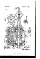
Within the casing of the engine I form an abutment chamber by mounting a rotary sleeve therein in a position to intersect said annular chamber and having a portion cut away to accom modate the piston in its revolution. I locate acore Within this sleeve, with the portion thereof that intersects the annular chamber milled away on the periphractic line of said chamber, while the surface of the core and the interior of that portion of the casing inclosing said rotary sleeve are correspondingly grooved from one milled edge of said core around said core and the interior of the casing to a point a distance from the other milled edge slightly greater than the width of the opening in said rotary sleeve, means being provided to cause the sleeve to rotate inunison with the revolution of the piston, a steam-cushion being adapted to act as a countervailing pressure upon said rotary sleeve to that exerted upon the opposite side thereof by the steam-pressure either direct or in expansion, a novel automatic exhaust-control, an automatically-variable cut-off combined reversing-gear and throttle, and novel means for packing the various points requiring it'also are embodied for full comprehension whereof and of my invention in its entirety reference must be had to the accom-- panying drawings,forming a part of this specification, in which like symbols indicate the same parts, and wherein-- Figure 1 is a complete vertical sectional View of my engine, taken on an axial plane; Fig. 12, a transverse vertical sectional view taken on line 2, Fig. 1, and illustrating particularly the exhaust-port and its controllingvalve; Fig. 3, a detail view illustrating in plan view the operative connection between the. governor-valve and its actuating-gear; Fig. 4, an enlarged transverse sectional View of one of my improved peripheral packingrings Fig. 5, a transverse vertical sectional View of the engine, taken on line 5 5, Fig.1, and illustrating the parts in position to first admit steam to the annular cylindrical chamber; Fig. 6, a similar view,but illustrating the parts in position to cut off the steam when theengineworks undermaximumload. Fig.7 is also a similar view, but illustrating in full lines and dotted lines, respectively, the parts in the positions they assume at the com mencement and completion of the interval that I designate the dead-point in the cycle of the revolution of the piston. Fig. 8 is a similar View, but taken on line 8 8, Fig. 1, and illustrating the combined throttle-valve and reversing-gear, the steam-chest, the automatic cut-off valve and governor-valve, and the steam-cushion. Fig. 9 is a horizontal sectional view taken on line 9, Fig. 1, and illustrating my improved combined throttle and reversing-gear. Fig. 10 is a transverse vertical sectional view looking toward the interior of the engine, taken on line 10 10, Fig. 1, and illustrating the pinion and gear-toothed surface of the rotary abutment. Fig. 11 is a similar View, but looking in the opposite direction and illustrating the interior of the caps that inclose the steam-chest and adjacent end of the rotary abutment; and Fig. 12 is a detail elevation, partly in section, of the front side of the piston as'it travels ahead. The direction of going ahead of the engine is indicated by plain arrows, and the direction of flow of the steam is indicated by feathered arrows.
The casing of my improved engine is of a form to present a main chamber 5 and an adjoining snbchamber 6, both extending from end to end of the casing,,the ends of the main chamber being closed by heads 7 7, cast in one with the casing and perforated to allow a shaft 8 to extend therethrough. A pinion 45 is mounted rigidly upon each end of the shaft outside of the casing, and between said pinions and the faces of the cylinder-heads I locate a pair of cups 150 and 151, with their rims in steam-tight contact with the cylinderheads, the adjacent portions of the cylinderheads and said rims being ground to from said steam-tight joint. These pinions and said cups 150 and 151' are inclosed by caps 66 and 4i6, said cups constituting, respectively, a steam-chest and an exhaust-chamber as the engine revolves ahead, while said caps have bearing-sleeves 67 for the shaft cast in one therewith. The steam-chest incloses a port 64, leading into one end of the cylinder of the engine, and the exhaust-chamber incloses a port 110, leading to the opposite end of the cylinder. The function of the pi nions just mentioned is to actuate a rotary abutment, to be presently described.
The casing is transverselydivided into two parts, which are secured together by a series of screw bolts 9, taking through flanges formed upon the adjoining edges thereof.
Vithin each half of the main chamber 5 and concentrically thereof a sleeve length 10 iscast, the two lengths conjointly inclosing the complete surface of the portion of the shaft within the cylinder (except for a small space midway of the length of said cylinder) and forming a partition that establishes between it and the inside face of said main chamber 5 an annular chamber 11, constituting the cylinder of the engine. The space between the ends of the sleeve portions lOis filled up by the edge of a disk 12, mounted rigidly upon the shaft and havinga piston 13, rigidly carried thereby and completely bisecting the said annular cylinder 11. The piston is in the form of a bar of a length and breadth to present a steam-bearing surface equal and conforming to the transverse area of said annular chamber 11 and of a thickness sufficient to accommodate a series of packing-strips. This piston is formed in tegrally with the periphery of the said disk 12, and one side thereof is of convex form, as at 61, and this disk is in turn secured rigidly to the shaft by means of a hub 62, weighted, as at (33, on the side thereof opposite to that at which the piston is mounted in order to counterbalance said piston, the portions of the weighted part of said hub on each side of the disk being preferably of conical form to enable an extended connection therebetween' and the shaft to be effected without weakening the connection between the sleeve portion 10 and the cylinder and at the same time enable the material of the cylinder-heads to he of suflicient thickness to allow the before-mentioned steam supply and exhaust ports Ga and 110, respectively, to be cut. v
A steam-tight joint is eifected between the edges of the piston and the peripheral wall of the chamber 11, the interior faces of the cylinder-heads 7 7; and the sleeve lengths '10 by means of a packingstrip 52, embedded in the radial outer edge of the piston, and a pair of rectangular strips 53, embedded in the ends and radial inner edge of the piston. These strips are caused to bear, respectively, upon the four walls of the annular chamber by means of a series of expansile coiled springs 54:, located in a series of sockets 55 in the piston edges and bearing outwardly upon said strips.
A steam-tight joint is established between the abutting edge of each sleeve portion and the disk by a metallic ring 14 in a recess 15, extending completely around said edge and having a series of axial borings or sockets 16, in which a series of expansile coiled springs 17 are located and bear outwardly upon the adjacent face of the said ring 11 and cause it in turn to bear upon the adjacent side of the disk.
The ends of the subchamber G are open on the vertical plane of the cylinder-heads 7 7,
and said ends communicate with theinterior of a pair of flanged caps 18 and 19, bolted, respectively, to flanges 20, cast in one with the casing, these caps being equal in depth to about one-fourth the distance between the cylinder heads in order to accommodate steam-cushions and said before-mentioned pinions 45, and at the same time provide extended bearings for the ends of the rotary abutment to be presently described. The interior of the portion of the casing inclosing the subchamber 6 is circumferentially grooved, as at 95, from the annular chamber 11 for about two-thirds of the length of the circumferential line of said subchamber.
A sleeve 21, corresponding approximately in diameter to that of the subchamber,extends therethrough and into the caps 18 and 19, and the ends thereof extend in close proximity to the ends of the caps. Steam-tight reing-rings 22, corresponding in diameter and radial thickness to the sleeve and set in annular recesses 23 in the interior of the ends of the caps, these rings being caused to bear upon the ends of the sleeve by a series of expansile coiled springs 24,1ocated in a series of borings or sockets 25, extending axially from said annularrecesses 23. Thesleeve 21 isformed with an opening 51, extending the full length of the space between the cylinder-heads 7 7 and of a width to allow the piston to pass therethrough with its edges in close proximity to but out of frictional contact with the edges thereof during the revolution of the piston, as will be presently shown. The circumference of this sleeve, adjacent to each end thereof, is geartoothed, as. at 30, to intermesh with 'the before-mentioned pinion 45, with which said gear-toothed portion corresponds in circumference. A core extends from end to end of the interior of this sleeve 21 and has a circumferential groove 96 midway of its length and extending like the before-mentioned groove 95 from the annular chamberll to a point on a radial line with, the end of said groove 95. This core is constructed of a pair of core portions, secured by bolts 35 rigidly to the end of each of the caps 18 and 19, each core portion being divided into two pieces 36 and 37. Theouter ends of the-pieces 36 are formed to present circular shoulders 38, talc-- ing into recesses in the ends of the caps, and the ends ofthe pieces 37 that adjoin the pieces 36 are circum ferentially recessed to accom modate packing-rings carried by theinterior of the sleeve 21. These packin g-rin gs each consists of a flanged ring 40, secured by bolts 41 to the interior of the sleeve and havinga series of sockets 42 formed therein to receive andlocalize a series of expansile coiled springs 43, while a ring 44, preferably of cast-iron, lies intermediate said springs and the face of the adjacent core-pieces 36. The diameter of the core-pieces 36 exceeds that of the pieces 37, and the sleeve is cored'out adjacent to its ends to accommodate the packing-rings 44c and the greater diameter of pieces 36, and at the same time to provide a shoulder to assist the bolts 41 in affording an abutment for the springs 43. The core pieces 37 have the lower portions thereof that intersect the annular cylindrical chamber 11 milled away, as
at 50, on the periphractic line of said chamher and on a line in the vertical plane of the interior of the cylinder-heads 7 7.
The steam is supplied to and exhausted from the cylinder 11 and the supply and exhaust automatically controlled as follows: The steam is fed to the steam-chest through a pipe 68 and thence passes through the port 64: to the cylinder 11. An automatic cut-off for said port 64 consists of a flanged valvular disk 69, cast in one with a short sleeve 77, mounted upon the shaft and connected thereto to rotate therewith, but free to slide axially thereof, by a slot 70 in said sleeve and a pin 71, carried rigidly by said shaftin a position to engage said slot. This disk is located in close proximity to the cylinder-head 7 in which it is countersunk, and has a series of openings 72, 73, 74, and of different areas, adapted to consecutivelycommunicate with said port 64. These openings extend, with intervals of connecting bridge pieces 7", for about one -half the circumference of said flanged disk. In constructing marine or other portable engines according to my invention a cut-off of this construction, or, under certain circumstances, with none other than the main port 72, will be found sufficient, as will be'clearly pointed out hereinafter.
In constructing engines according to my invention for general purposes and adaptedfor use either as a stationary or a portable engine I provide means for automatically controlling the amount of steam or other motive fluid employedin order to maintain uniform velocity with a varying resistance.
This automatic controller or governor consists of a segmental valve-plate 78, having ports 82, and a series of-valvular bridge portions 79, 80,
and 81 of slightly-greater area than the ports 73, 74, and 75, respectively. This plate 78 is seated upon the disk 69-and formed in one I with a short sleeve 83,offset,as at 84, to fit over the sleeve 77 and the'shaft and having a diagonal slot 85. The shaft is bored longitudinally from the adjacent end thereof to a point about in a'line with the cut-off,-and a spindle 87 extends within this boring and has its inner end offset, as at 88, to extend through an axial slot 89 in the shaft and take into the diagonal slot in the sleeve 83,and a stufflng= box 90 closes the end of the shaft. A collar 91, having two pairs of lugs 92, arranged diametrically opposite to one another, issecured rigidly upon the outer end of the spindle 87 by a set-screw 93. A pair of rods 94 are each pivotally connected to one of said pairs of lugs, and the other ends thereof are pivotally connected to a pair of governorballs .95, which are in turn pivotally connected by a pair'of rods 96 to the lugs 97 of a collar 98 similar to the collar 91, but rigidly mounted upon the shaft, while an expansile coiled spring 99 encircles the spindle 87 and bears between the collar 91 and the stuffingbox 90.
In order to allow the valvular plate 78 to have perfect freedom of movement over its seat 69, I form a recess 92 on the outer face of each bridge-piece of the disk, and provide each bridge-piece of the valvular plate 75 with a small perforation, thus causing a steam-cushion to be formed behind the bridge pieces of the valvular plate 78 whether they bear over the bridge-piece of said flanged disk 69 or over the face of the cylinder-head.
The exhaust-port 100 from the cylinder is, as before mentioned, cut through the portion of the cylinder-head 7 inclosed by the exhaust-chamber cylinder-head 7 similarly to the steam-supply port 6% and effects a communication between the annular cylindrical which is recessed to accommodate it.
chamber 11 and said exhaust-chamber. The cup, as before mentioned, constitutes the exhaust-chamber, and the cap 46, like the cap 66, is formed with a bearing-sleeve for the shaft.
r In order to prevent the escape of steam from the cylinder to the shaft-bearings, I recess the inside faces of the ends of the caps 66 and 46, as at 160, to accommodate circular shoulders 161, formed upon the outer faces of the pinions 45, while circular recesses 162, concentric of the recesses 160, accommodate the packing-rings. Each of these packingrings consists of an intact ring 163, fitting closely in each of said recesses 162 and held byascries of coiled springs 164. Asegmental valve-plate 101, formed in one with a short sleeve 102, is secured rigidly through said sleeve upon the shaft within the cup 151 and in close contact with the cylinder-head 7, This plate is of a circumferential length to completely close the port 100 during a dead-point interval clearly pointed out in the description of the operation hereinafter.
My improved combined throttle-valve and reversing-gear consists of a cylindrical chamber 105, having a horizontal valve-seat, a portion 106 whereof encircles and other portions 107 and 108 whereof separate the mouths of four ports 109,110, 112, and 113, respectively. The port 109 communicates with the steamsupply pipe'114, the port 110 communicates with the steam-exhaust pipe 111, and the ports 112 and 113 communicate, respectively, through pipe 68 (before mentioned) with the stearmchest 6S and a pipe 116 with the exk haust-chamber 46.. Resting upon this'seat is a valve in the form of a circular plate 115,
having slightly more than one-half of its under side recessed, as at 114, on a line concentrically thereof and of a sufficiently-less radius than that of the periphery of the plate to form an annular bearing-face 117, adapted to rest upon the circular portion 106' of the valve-seat, while the remaining solid portion of the plate has a radially-projected V-notch 118 cut centrally thereof and the upper portion of the plate contiguous to said notch cut away in an angular plane from the edges of the-notch upwardly toward the center of the upper surface of the plate, which surface is of convex form. This valvular plateis mounted rigidly upon the lower end of a stem 119, extending upwardly through a short sleeve 121, formed concentrically of a cover and'provided with a stuffing box 122, the cover being screwed into the cylinder 105, while a handle 123 is mounted rigidly upon the upper end of the stem 119.
The construction of engine thus far described will allow of reversal and will be found both economic and to possess great efficiency; but I have discovered that the wearing relation between the rotary abutment-sleeve and the partitioning-sleeve 10 of the cylinder is very great and the cause of much unnecessary the interior of the intact end portions of the abutment-sleeve by a series of expansile springs 127, set in sockets 128 in said corepieces, The chamber 129 thus formed is made to communicate with the abutment-chamber by a passage 130, bored therefrom through said outer core-pieces 36 and the central corepieces 37 to the angle formed by the milledaway portion, as at 50, of the middle corepieces 37, while draw-off passages 131 for the condensed steam are bored from the side of the core opposite to said chambers 129 to the outer ends of the outer core-pieces 36, where theycommunicate with draw-off pipes 132,
provided with stop-cocks 133.
The operation of my improved rotary engine is as follows: .In order to start the engine, the handle 123 should be moved to' the position shown in Fig. 8, thus causing the recess 114 in the valve-plate 115 of the throttle to register with both ports 112 and 110 and the V- groove to register withthe port 113, thereby establishiuga direct communication from the steam-supply pipe 144 through ports 109 and 113 to the steam-chest 66 and from the exhaust-chamber 46 through pipe 155 and ports 112,recess114, and port 110 to the exhaust-pipe 111. The admission of the steam to the annular cylinder 11 will then be under the control only of the automatic cut-off valve 69 and the governor-valve 7 8. Upon starting the engine the steam will pass from the steamchest through port 64 into the portion of the annular cylinder 11 that is inclosed by the abutment-sleeve 21, as shown in Fig. 8. The steam will continue to be admitted to act directly upon the piston for from fifty-five degrees to approximately one hundred and eighty degrees of the revolution thereof, accordin to the resistance to or steam-pressure acting upon the engine, after which, excepting for a comparatively speaking diminutive dead-point, (the interval before mentioned,) the balance of the stroke will be under the power of expansion, as will be presently pointed out. As the piston revolves and with it the shaft rotates in the direction indicated the abutment-sleeve 21 will through the gears 45 and 30 be rotated in an opposite direction, and the steam will then be admitted between the after face of the piston and the adjacent portion of the abutment-sleeve intersecting the annular cylinder. It will not, however, abut upon this portion of the sleeve, but will find its way through groove 95, the opening 51 in the abutment-sleeve 21, and the groove 96 to the chamber 50, where abutment will take place, with the result that much greater force will be exerted upon the interior of the sleeve at that point.than upon the exterior of the portion thereof that intersects the annular cylinder. The abutting force that acts with such excessive pressure upon the interior of the sleeve is compensated to a certain degree by the countervailing pressure of the before-mentioned steam-cushion 129, which must not, however, exert sufficient energy to be detrimental to the steam-tight relation between the abutment-sleeve and the partitioning-sleeve 10. The steam-pressure upon the engine is equalized to the resistance thereto by means of the governor-balls, which act upon the well-known centrifugal principle, and to accommodate a decreasing resistance will draw away from the shaft 8, thereby causing the spindle to move into the shaft and the offset end 88 thereof to act upon the inclined face of the slot 85in sleeve 83 of the valvular plate 78, which it rotates in the direction indicated in Fig. 3. thus gradually closing the ports 73, 74, and 75 until the pressure and resistance are approximately equalized. To accommodate an increasing resistance, a reverse action will take place. During the cycle of rotation of the engine there will be an interval when the steam-tight relation between the rotary abutment and the partitioning-"sleevewill be broken. This interval is the deadpoint before mentioned and occurs between the time that the forward axial edge of the opening 51 (while the sleeve 21 is rotating in either. direction) leaves the vertical plane of the partitioning-sleeve and the time that the after axial edge reaches said vertical plane. During this interval the exhaust-control valve 102 incidentally closes the exhaust-port 100, which for the rest of the time is open, and the engine completes its cycle by its own momentum, the true function of this exhaust-valve being exerted as the engine reverses, but the incidental function just alluded to is of advantage to the engine for economical purposes, as it traps and retains in the cylinder of the engine a body of steam representing an energy that would otherwise be lost.
To reverse the engine, the handle 123 should be moved to the position shown in chain-lines in Fig. 9, thus causing the recess 11-1 to register with both ports 110 and 113 and the V-groove to register with the port 112, thereby establishing a direct communication from the steam-supply pipe 144 through the ports 109 and 112 to what has constituted the exhaust chamber as the engine traveled ahead, but that now in reversal constitutes the steam-chest 46 and a direct com munication from the (under the prevailing conditions) exhaust-chamber (56 through port 113,recess 114,and port 110 to the exhaust-pipe 111. The cycle of the engine while running in reversal and the relative action of all the parts are directly the reverse of that just described, except that the steam is continually exhausting through the space between the flanged disk 69 and the face of the cylinder-head into the chamber 66 and out, as described, the sliding connection '71 between said disk 69 and the shaft allowing the steam to act detrusively upon and displace said disk, while the steam is automatically cut off by the segmental valve 102 during the interval that has before been designated the dead-point, as otherwise a direct passage would be established from the steam-supply to the exhaust port and considerable steam lost.
By inclining the face of the pistonthat is, the leading or forward face while the engine travels aheadthe steam-tight relation between said face and the forward axial edge of the opening 51 is rendered uniform during the full time they are in close proximity to one another.
It is obvious that, ifdesired, without departing from the spirit of my invention the flanged plate and segmental valvular plate constituting the automatically-variable outoff or governor can have the portions thereof with the ports therein cutaway. This, however, I consider would impair the efficiency of the governor to a certain extent. It is also obvious that by connecting the shaft of my engine to any suitable driving-gear, the engine will serve as a pump.
What I claim is as follows:
1. In a rotary engine, a cylinder having a radial extension, a piston revoluble within said cylinder; a rotary abutment located within said radial extension, and consisting of a sleeve having an opening in its side of sufficient area to accommodate the piston in its revolution; a stationary core extending through said sleeve from end to end thereof and having a portion milled away on the periphractic line of the cylinder; means for causing said sleeve to rotate in an opposite direction to the piston, and a steam supply to and exhaust from said cylinder, for the purpose set forth.
2. In a rotary engine, a cylinder having a radial extension with an interior peripheral groove; a piston revoluble within said cylinder; a rotary abutment located within said radial extension, and consisting of a sleeve having an opening in its side of sufficient area to accommodate the piston in its revolution, the said groove extendingfrom one line of junction of said cylinder and extension to a point distant'from the other line of juncture greater than the width of the opening in the side of the abutment; a stationary core extending through said sleeve from end to end thereof and having a portion milled away on the periphractic line of the cylinder and having a peripheral groove extending around the cylindrical portion from one milled edge to a point in the radial plane of the corresponding end of the first-mentioned groove; means for causing said sleeve to rotate in an opposite direction to the piston; and a steam supply to and exhaust from said cylinder, for the purpose set forth.
3. In a rotary engine, a cylinder having a radial extension; a shaft extending through said cylinder from end to end thereof, a piston revoluble within said cylinder; a stationary partitioning sleeve inclosing approximately the complete portion of the shaft within said cylinder; means for connecting the piston to the portion of the shaft within the cylinder not inclosed by said sleeve; a rotary sleeve located within said radial extension, saidsleeve having an opening in its side of sufficient area to accommodate the piston in its revolution; a stationary core extending through said sleeve from end to end thereof and having a portion milled away on the periphractic line of the cylinder; means for causing said sleeve to rotate in an oppo site direction to the piston, for the purpose set forth.
4. In a rotary engine, a cylinder having a radial extension of greater length than the interior of the cylinder; a shaft extending through said cylinder from end to end thereof a piston revoluble within said cylinder; a rotary sleeve located within and extending from end to end of said radial extension, said sleeve having an opening in its side of sufficient area to accommodate the piston in its revolution; a stationary core extending through said sleeve from end to end thereof and having a portion milled away on the periphractic line of the cylinder and a portion adjacent to each end milled away at the opposite side, and a steam-passage extending from said firstmentioned milled-away portion to each of said last-mentioned milled-away portions; means for causing said sleeve'to rotatein an opposite direction to the piston, for the purpose set forth.
5. In a rotary engine, a cylinder having a radial extension of greater length than the interior of the cylinder; -a shaft extending through said cylinder from end to end thereof, a piston revoluble Within said cylinder; a stationary sleeve inclosin g approximately the complete portion of the shaft within said cylinder; means for connecting the piston to the portion of the shaft within the cylinder notinciosed by said sleeve; arotary sleeve located within and extending from end to end of said radial extension, said sleeve having an opening in its side of sufficient area to accom modate the piston in its revolution; a stationary core extending through said sleeve from end to end thereof and having aportion milled away on the periphractic line of the cylinder; and a portion adjacent to each end milledaway at the opposite side, and asteam-passage extending from said first mentioned milled-away portion to each of said last-mentioned milledaway portions; means for causing said sleeve to rotate in an opposite direction to the pisten; for the purpose set forth.
6. In a rotary engine, the combination of a cylinder, a shaft extending concentrically through said cylinder, and having a radial extension with an interior peripheral groove, a divided partitioning-sleeve carried rigidly by the cylinder-heads and inclosing approximately the complete portion of the shaft within said cylinder; a piston completely bisecting the space between said sleeve and the walls of the cylinder; means for rigidly connecting the piston to that portion of the shaft means for closing the space between the ends of the divided partitioning-sleeve; a rotary abutment located within the extension of the cylinder, and consisting of a sleeve extending axially through the cylinder and having an opening in its side equal in length to the axial length of the interior of the cylinder and of sufficient width to accommodate the piston in its revolution; means for causing said shaft to rotate the abutment in an opposite direction to itself; means for establishing steam-tight relation between the ends of the sleeve and the body of the cylinder; a core extending through said sleeve from end to end thereof and havinga portion milled away on the periphractic line of the cylinder and having a peripheral groove extending around the cylindrical portion from one milled edge to a point in the radial plane of the corresponding end of the first-mentioned groove which extends from one line of junction of said cylinder and radial extension to a point distant from the other line ofjuncture greater than the width of the opening in the abutment; a steam-inlet port to said cylinder; an automatic cut-off valve for said port; and an exhaust-port from said cylinder, substantially as described and for the purpose set forth. a
7. In a rotary engine, the combination of a cylinder, a shaft extending concentrically through said cylinder, and having an extension with an interior peripheral groove, a divided partitioning-sleeve carried rigidly by the cylinder-heads and inclosing approximate'ly the complete portion of the shaft within said cylinder; a disk secured rigidly to said shaft and corresponding in diameter to that of the exterior of the sleeve; a piston secured rigidly to the periphery of said disk, and completely bisectin g the space'between said sleeve and the walls of the cylinder; a rotary abutment located within the extension of the cylinder, and consisting of a sleeve extending axially through the cylinder and having an opening in its side equal in length to the axial length of the interior of the cylinder and of sufficient width to accommodate the piston in its revolution; means for causing said shaft to rotate the abutment in an opposite direction to itself; means for establishing steamtight relation between the ends of the sleeve and the body of the cylinder; a core extending through said abutment-sleeve from end 7 to end. thereof and having a portion milled not inclosed by said partitioning-sleeve;.
away 011 the periphractic line of the cylinder and having a peripheral groove extending around the cylindrical portion from one milled edge to a point in the radial plane of the corresponding end of the first-mentioned groove which extends from one line of junction of said cylinder and radial extension to a point distant from the other line of juncture,greater than the width of the opening in the abutment; a steam-inlet port to said cylinder; an
, portion of the shaft within said cylinder; a
disk secured rigidly to said shaft and corresponding in diameter to that of the exterior of the sleeve; a piston secured rigidly to the periphery of said disk, and completely bisecting the space between said sleeve and the walls of the cylinder; a rotary abutment located within the extension of the cylinder, and consisting of a sleeve extending axially through the cylinder and having an opening in its side equal in length to the axial length of the interior of the cylinder and of sufficient width to accommodate the piston in its revolution; means for causing said shaft to rotate the abutment in an opposite direction to itself; means for establishing steam-tight relation between the ends of the sleeve and the body of the cylinder; a core extending through said sleeve from end to end thereof and having a portion milled away on the periphraetic line of the cylinder and having a peripheral groove extending around the cylindrical portion from one milled edge to a point in the radial plane of the corresponding end of the first-mentioned groove which extends from one line of junction of said cylinder and radial extension to a point distant from the other line of juncture greater than the width of the opening in the abutment; a steam-inlet port to said cylinder; an automatic cut-off valve for said port; and an exhaust-port from said cylinder, substantially as described and for the purpose set forth.
9. In a rotary engine, the combination of a cylinder a shaft extending concentrically through said cylinder the interior whereof is rectangular in axial plane, and circular in contour transversely of said axial plane, and having a radial extension with an interior peripheral groove, a divided partitioningsleeve carried rigidly by the cylinder-heads and inclosing approximately the complete portion of the shaft within said cylinder; a disk corresponding in diameter to that of the exterior of the sleeve and secured rigidly to said shaft by a hub weighted at one side; a piston secured rigidly to the periphery of said disk at a point diametrically opposite to the weightand completely bisecting the space between said sleeve and the Walls of the cylinder; a rotary abutment located within the extension of the cylinder and consisting of a sleeve extending axially through the cylinder and having an opening in its side equal in length to the axial length of the interior of the cylinder and of sufficient width to accommodate the piston in its revolution; means for causing said shaft to rotate the abutment in an opposite direction to itself; means for establishing steam-tight relation between the ends of the sleeve and the body of the cylinder; a core extending through said sleeve from end to end thereof and having a portion milled away on the periphractic line of the cylinder and having a peripheral groove extending around the cylindrical portion from one milled edge to a point in the radial plane of the corresponding end of the first-mentioned groove which extends from one line of junction of said cylinder and extension to a point distant from the other line of juncture greater than the width of the opening in the abutment; a steam-inlet port to said cylinder; an automatic cut-off valve for said port consisting of a disk having one or more ports therein, and mounted upon and rotatable with the shaft in close proximity to the said inletport, and an exhaust-port from said cylinder substantially as described and for the purpose set forth.
lO. In a rotary engine, the combination of a cylinder, a shaft extending concentrically through said cylinder, the interior whereof is rectangular in axial plane, and circular in contour transversely of said axial plane and having a radial extension with an interior peripheral groove, a divided partitioningsleeve carried rigidly by the cylinder-heads and inclosing approximately the complete portion of the shaft within said cylinder; a disk secured rigidly to said shaft and corresponding in diameter to that of the exterior of the sleeve; a piston secured rigidly to the periphery of said disk, and completely bisecting the space between said sleeve and the walls of the cylinder; a rotary abutment located within the extension of the cylinder, and consisting of a sleeve extending axially through the cylinder and having an opening in its side equal in length to the axial length of the interior of the cylinder and of sufficient width to accommodate a piston in its revolution; means for causing said shaft to rotate the abutment in an opposite direction toitself; means for establishing steam-tight relation between the ends of the sleeve and the body of the cylinder; a core extending through said sleeve from end to end thereof and having a portion milled away on the periphractic line of the cylinder and having a peripheral groove extending around the cylindrical portion from one milled edge to a point in the radial plane of the corresponding end of the first-mentioned groove which extends from one line of junction of said cylinder and extension to a point distant from the other line of juncture greater than the width of the opening in the abutment; a steam-inlet port to said cylinder; an automatic cut-off valve for said port; and an exhaust-port from said cylinder and means for controlling said exhaust-port, substantially as described and for the purpose set forth.
11. In a rotary engine, the combination of a cylinder a shaft extending concentrically through said cylinder the interior whereof is rectangular in axial plane, and circular in contour transversely of said axial plane, and having a radial extension with an interior peripheral groove, a divided partitioningsleeve carried rigidly by the cylinder-heads and inclosing approximately the complete portion of the shaft within said cylinder; a disk corresponding in diameter to that of the exterior of the sleeve and secured rigidly to said shaft by a hub weighted at one side; a piston secured rigidly to the periphery of said disk at a point diametrically opposite to the weightand completely bisecting the space between said sleeve and the walls of the cylinder; a rotary abutment located within the extension of the cylinder and consisting of a sleeve extending axially through the cylinder and having an opening in its side equal in length to the axial length of the interior of the cylinder and of sufficient width to accommodate the pistoninits revolution; means for causing said shaft to-rotate the abutment in an opposite direction to itself; means for establishing steam-tight relation between the ends of the sleeve and the body of the cylinder; a core extending through said sleeve from end to end thereof and having a portion milled away on the periphractic line of the cylinder and having a peripheral groove extending around the cylindrical portion from one milled edge to a pointin the radial plane of the corresponding end of the first-mentioned groove which extends from one line of junction of said cylinder and extension to a point distant from the other line of juncture greater than the width of the opening in the abutment; a steam-inlet port to said cylinder; an automatic cut-off valve for said port concentric of a disk having one or more ports therein, and mounted upon and rotatable with the shaft in close proximity to the said inlet-port, and an exhaust-port from said cylinder and means for controlling said exhaustport, substantially as described and for the purpose set forth.
12. In a rotary engine, the combination of a cylinder, a shaft extending concentrically through said cylinder, the interior whereof is rectangular in axial plane, and circular in contour transversely of said axial plane and having a radial extension with an interior peripheral groove, a divided partitioningslceve carried rigidly by the cylinder-heads and inclosing approximately the complete portion of the shaft within said cylinder; a disk secured rigidly to said shaft and corresponding in diameter to that of the exterior of the sleeve; a piston secured rigidly to the periphery of said disk, and completely bisecting the space between said sleeves and the walls of the cylinder; a rotary abutment located within the extension of the cylinder, and consisting of a sleeve extending axially through the cylinder and having an opening in its side equal in length to the axial length of the interior of the cylinder and of sufficient width to accommodate the piston in its revolution; means for causing said shaft to rotate the abutment in an opposite direction to itself; means for establishing steam-tight relation between the ends of the sleeve and the body of the cylinder; a core extending through said sleeve from end to end thereof and having a portion milled away on the periphractic line of the cylinder and having a peripheral groove extending around the cylindrical portion from one milled end of the first-mentioned groove which extends from one line of junction of said cylinder and extension to a point distant from the other line of juncture greater than the width of the opening in the'abutment; a steam -cushion adapted to partially support the abutmentsleeve; a steam-inlet port to said cylinder; an automatic cut-off valve for said port, and an exhaust from said cylinder, substantially as described and for the purpose set forth.
13. In a rotary engine, the combination of a casing comprising a main chamber and an auxiliary chamber, the auxiliary chamber having its ends closed by cylindrical caps, a shaft extending concentrically through said main chamber, said auxiliary chamber having an interior peripheral groove, a divided partitioning-sleeve carried rigidly by the cylinder-heads and inclosing approximately the complete portion of the shaft within said cylinder; a disk secured rigidly to said shaft and corresponding in diameter to that of the exterior of the sleeve; a piston secured rigidly to the periphery of said disk and completely bisecting the space between said sleeve and the walls of the cylinder; a rotary abutment located within the extension of the cylinder and consisting of a sleeve extending axially through the auxiliary chamber and into the caps at the ends thereof and having an opening in its side equal in length to the axial length of the interior of the main chamber and of sufficient width to accommodate the piston in its revolution; means for causing said shaft to rotate the abutment in an opposite direction to itself; means for establishing steam-tight relation between the ends of the sleeve and the body of the cylinder; a core extending through said sleeve from end to end thereof and having a portion milled away on the periphractic line of the main chamber and having a peripheral groove extending around the cylindrical portion from e iao it;
one milled edge to a point in the radial plane of the corresponding end of the first-mentioned groove, which extends from one line of junction of said main and auxiliary chambers to a point distant from the other line of juncture greater than the width of the opening in the abutment; asteam-cushion adapted to partially support the abutment-sleeve and consisting of a recess formed in the cylindrical surface of the portion of said core within the cups on a line diametrically opposite to the forward half (relatively to the going-ahead travel of the piston) of the portion of the abutment-sleeve that intersects the cylinder, a communicating passage connecting said recess with the abutment-chamber, and an expansile packing-ring carried by the interior of said sleeve and bearing upon one side of a circumferential recess cut in said core at the inner end of the recess just mentioned and a pair of expansile strips extending axially one along each side edge of said first-mentioned recess and from said packing-ring to the adjacent end of the'core, expansile steam-packing strips; a steam-inlet port to said main chamber; an automatic cut-off valve for said port and an exhaust port from said main chamber, substantially as described and for the purpose set forth.
14. In an engine, a valvular plate having'a recess formed in its outer face; a second valvular plate facing the steam-supply and having the portion thereof located over said recess perforated and adapted to slide across the face of said first-mentioned plate.
15. In combination with the cylinder of arotary engine, an automatically-variable cut-off consisting of a plate having one or more ports therein and the portion adjacent to said port or ports recessed on its outer face, said port or ports at intervals registering with the steam-inlet port to the engine; means for connecting said plate to a rotating part of the engine to rotate therewith, a valvular plate movable over the face of said first-mentioned plate to control the ports therein and having the portion thereof located over said recess or recesses perforated; and means under the influence of the variance of the resistance to the engine for moving said last-mentioned plate substantially as described and for the purpose set forth.
16. In combination with the cylinder of a rotary engine,an automaticallywariable cut-off, consisting of a valvular plate having a recess formed in'its outer face; means for connecting said plate to a rotating part of the engine to rotate therewith, the steam-inlet port to said cylinder being located in the path of said plate; a second valvular plate having the portion thereof located over said recess perforated and adapted to slide across the face of said first-mentioned plate; and means under the influence of the variance of the resistance to the engine for moving said last-mentioned plate and said cut-off being movable to and from the cylinder-head in which said inletport is cut, said movement of the cut-off be ing automatically effected by the reversal of the direction of travel of the steam fed to the engine, substantially as described, for the purpose set forth.
17. In combination with the cylinder of a re; tary engine, an automatically-variable cut-off consisting of a plate having a series of ports therein the body-pieces between said ports having recesses formed in their outer faces, said ports at intervals registering successively with the steam-inlet port to the engine; means for connectingsaid plate to a rotating part of the engine to rotate therewith; a perforated valvular plate movable over the face of; said first-mentioned plate to simultaneously control the ports therein; and means under the influence of the variance of the re sistance to the engine for moving said lastmentioned plate and said cut-off being movable to and from the cylinder-head in which said inlet-port is cut, said movement of the cut-off being automatically efiected by the 'reversal of the direction of travel of the steam-feed to the engine, substantially as described and for the purpose set forth.
18. In combination with the cylinder and shaft of a rotary engine, of an automaticallyvariable cut-off consisting of a plate having a series of ports of different area therein; said plate overlapping the steam-inlet port to the cylinder; means for connecting said plate to the shaft to rotate therewith; a segmental plate havinga series of valvular bridge-pieces to control said series of ports and formed in one with an interiorly-offset sleeve taking over said shaft and said first-mentioned sleeve; said last-mentioned sleeve being formed with a pair of diametrically opposite diagonal slots; the shaft having an axial slot extend ing diametrically therethrough and intersecting said diagonal slots, and an axial boring extending from the adjacent end of the shaft to said axial slot, a spindle extending through said boring and having a transverse piece on the inner end thereof and projecting through said axial slot and taking into said diagonal slots; a stuffing-box closing the outer end of said shaft; a collar secured rigidly upon the outer end of said spindle; a coiled spring hearing between said collar and stuliing-box; a pair of lugs projecting radially from diametrically-opposite sides of said collar; a collar secured rigidly upon the shaft adjacent to the outer end thereof; a pair of governor-balls; two pairs of rods pivotally connecting said governor-balls to the lugs upon said respective collars; a steam-chest encircling said I shaft and inclosing said plates; a stuffing-box for packing the point at which the shaft passes out of the steam-chest; a steam-supply to said steam-chest; a segmental valvular plate for controlling the exhaust-port from said cylinder and means for connecting said latter plate to the shaft, substantially as described and for the purpose set forth.
19. In combination with the cylinder and shaft of a rotary engine, of an automaticallyvariable cut-off, consisting of a plate having a series of ports of different area therein the bridge-piece between said ports having recesses formed in their outer faces; said plate overlapping the steam-inlet port to the cylinder; means for connecting said plate to the shaft to rotate therewith; a segmental plate having a series of perforated valvular bridgepieces to control said series of ports, and formed in one with an interiorly-offset sleeve taking over said shaft and said first-mentioned sleeve; said last-mentioned sleeve being formed with a pair of diametrically-opposite diagonal slots; the shaft having anaxial slot extending diametrically therethrough and intersecting said diagonal slots, and an axial boring extending from the adjacent end of the shaft to said axial slot, a spindle extending through said boring and having a transverse piece 011 the inner end thereof and projecting through said axial slot and takinginto said diagonal slots; a stuffing-box closing the outer end of said shaft; a collar secured rigidly upon the outer end of said spindle; a coiled spring bearing between said collar and stuff ing-box; apair oflugs projectingradiallyfrom diametrically-opposite sides of said collar; a collar secured rigidly upon the shaft adjacent to the outer end thereof; a pair of governorballs; two pairs of rods pivotally connecting said governor-balls to the lu upon said re spective collars; a steam-chest encircling said shaft and inclosin g said plates; a stuffing-box for packing the pointat which the shaft passes out of the steam-chest; a steam-supply to said steam-chest; a segmental valvular plate for controlling the exhaust-port fromsaid cylinder and means for connecting said latter plate to the shaft, substantially as described and for the purpose set forth.
20. In combination with the cylinder and shaft of a rotary engine, of an automaticallyvariable cut-off consisting of a plate having a series of ports of different area therein, said plate overlapping the steam-inlet port to the cylinder and being formed in one with an axially-slotted sleeve adapted to take over said shaft; a pin carried rigidly by the shaft and taking into the slot in said sleeve; a segmental plate having a series of valvular bridgepieccs to control said series of ports and formed in one with an interiorly-oifset sleeve taking over said shaft and said first-mentioned sleeve; said last mentioned sleeve being formed with a pair of diametrically-opposite diagonal slots; the shaft having an axial slot extending diametrically therethrough and intersecting said diagonal slots, and an axial boring extending from the adjacent end of the shaft to said axial slot, a spindle extending through said boring and having a transverse piece on the inner end thereof and projectin g through said axial slot and taking into said diagonal slots; a stuffing-box closing the outer end of said shaft a collar secured rigidly upon the outer end of said spindle; a
coiled spring bearing between said collar andstuffing-box; a pair of lugs projecting radially from diametrically-opposite sides of said collar; a collar secured rigidly upon the shaft adjacent to the outer end thereof; a pair of governor-balls; two pairs of rods pivotally connecting said governor-balls to the lugs upon said respective collars; a steam-chest encircling said shaft and inclosin g said plates; a stuffing-box for packing the point at which the shaft passes out of the steam-chest; a steam-supply to said steam-chest; a segmental valvular plate for controlling the exhaustport from said cylinder and means for connectin g said latter plate to the shaft, substantially as described and for the purpose set forth.
21. In combination with the cylinder and shaft of a rotary engine, of an automaticallyvariable cut-off consisting of a plate having a series of ports of different area therein, the bridge-piece between said ports having recesses formed in their outer faces; said plate overlapping the steam-inlet port to the cylinder and being formed in one with an axiallyslotted sleeve adapted to take over said shaft; a pin carried rigidly by the shaft and taking into the slot in said sleeve; a segmental plate having a series of perforated valvular bridgepieces to control said series of ports and formed in one with an interiorly-ofiset sleeve taking over said shaft and said first-mentioned sleeve; said last-mentioned sleeve being formed with a diagonal slot; theshaft having an axial slot extending diametrically therethrongh and intersecting said diagonal slot, and an axial boring extending from the adjacent end of the shaft to said axial slot, a spindle extending through said boring and having its inner end offset and projecting through said axial slot and taking into said diagonal slot; a stufiing-box closing the outer end of said shaft; a collar secured rigidly upon the outer end of said spindle; a coiled spring bearing between said collar and studing-bpx; a pair of lugs projecting radially from diametrically-opposite sides of said collar; a collar secured rigidly upon the shaft adjacent to the outer end thereof; a pair of governor-balls; two pairs of rods pivotally connecting said governor-balls to the lugs upon said respective collars; a steam-chest encircling said shaft and inclosin g said plates; a stuffing-box for packing the point at which the shaft passes out of the steam-chest; a steam-s11 pply to said steam-chest; a segmental valvular plate for controlling the exhaustport from said cylinder and means for connecting said latter plate to the shaft, substantially as described and for the purpose set forth.
22. An expansible steam-packing ring consistin g of a carrying-ring L-shaped in crosssection secured rigidiy to one of the parts besubstantially as described and for the purtween which steam-tight relation is required and having a series of sockets in the axial face thereof adjacent to the other part, a bearing-ring located in the recess of said L- piece in contact with said other part; and a series of expansile springs located in said sockets and bearing upon said bearing-ring,
pose set forth. 1o
. In testimony whereof I have affixed my sig' nature in presence of two witnesses.
. VICTOR FILTEAU. Witnesses:
WILLIAM K. MoFEAT, FRED. J. SEARS.
Priority Applications (1)
| Application Number | Priority Date | Filing Date | Title |
|---|---|---|---|
| US70383899A US648024A (en) | 1899-01-30 | 1899-01-30 | Rotary engine. |
Applications Claiming Priority (1)
| Application Number | Priority Date | Filing Date | Title |
|---|---|---|---|
| US70383899A US648024A (en) | 1899-01-30 | 1899-01-30 | Rotary engine. |
Publications (1)
| Publication Number | Publication Date |
|---|---|
| US648024A true US648024A (en) | 1900-04-24 |
Family
ID=2716596
Family Applications (1)
| Application Number | Title | Priority Date | Filing Date |
|---|---|---|---|
| US70383899A Expired - Lifetime US648024A (en) | 1899-01-30 | 1899-01-30 | Rotary engine. |
Country Status (1)
| Country | Link |
|---|---|
| US (1) | US648024A (en) |
Cited By (1)
| Publication number | Priority date | Publication date | Assignee | Title |
|---|---|---|---|---|
| US2913990A (en) * | 1952-11-28 | 1959-11-24 | Rockwell Mfg Co | Hydraulic mechanism |
-
1899
- 1899-01-30 US US70383899A patent/US648024A/en not_active Expired - Lifetime
Cited By (1)
| Publication number | Priority date | Publication date | Assignee | Title |
|---|---|---|---|---|
| US2913990A (en) * | 1952-11-28 | 1959-11-24 | Rockwell Mfg Co | Hydraulic mechanism |
Similar Documents
| Publication | Publication Date | Title |
|---|---|---|
| US711083A (en) | Rotary engine. | |
| US648024A (en) | Rotary engine. | |
| US1026165A (en) | Rotary engine. | |
| US270160A (en) | Rotary steam-engine | |
| US663972A (en) | Steam-engine. | |
| US602630A (en) | Rotary engine | |
| US823228A (en) | Rotary engine. | |
| US557476A (en) | Rotaet engine | |
| US361598A (en) | Half to damas ltjtz | |
| US734944A (en) | Rotary engine. | |
| US633730A (en) | Rotary steam-engine. | |
| US645484A (en) | Rotary engine. | |
| US1176643A (en) | Rotary engine. | |
| US249620A (en) | David o | |
| US696047A (en) | Rotary engine. | |
| US1012850A (en) | Rotary engine. | |
| US657826A (en) | Rotary engine. | |
| US616662A (en) | Rotary engine | |
| US282001A (en) | kissam | |
| US636829A (en) | Rotary engine. | |
| US791939A (en) | Rotary engine. | |
| US744614A (en) | Rotary engine. | |
| US801189A (en) | Rotary engine. | |
| US444087A (en) | Pleau | |
| US791302A (en) | Rotary engine. |