US6471406B1 - Side-bolt bearing caps - Google Patents
Side-bolt bearing caps Download PDFInfo
- Publication number
- US6471406B1 US6471406B1 US09/698,671 US69867100A US6471406B1 US 6471406 B1 US6471406 B1 US 6471406B1 US 69867100 A US69867100 A US 69867100A US 6471406 B1 US6471406 B1 US 6471406B1
- Authority
- US
- United States
- Prior art keywords
- bearing cap
- main bearing
- teeth
- face
- powder metal
- Prior art date
- Legal status (The legal status is an assumption and is not a legal conclusion. Google has not performed a legal analysis and makes no representation as to the accuracy of the status listed.)
- Expired - Lifetime, expires
Links
Images


Classifications
-
- F—MECHANICAL ENGINEERING; LIGHTING; HEATING; WEAPONS; BLASTING
- F16—ENGINEERING ELEMENTS AND UNITS; GENERAL MEASURES FOR PRODUCING AND MAINTAINING EFFECTIVE FUNCTIONING OF MACHINES OR INSTALLATIONS; THERMAL INSULATION IN GENERAL
- F16C—SHAFTS; FLEXIBLE SHAFTS; ELEMENTS OR CRANKSHAFT MECHANISMS; ROTARY BODIES OTHER THAN GEARING ELEMENTS; BEARINGS
- F16C43/00—Assembling bearings
- F16C43/02—Assembling sliding-contact bearings
-
- B—PERFORMING OPERATIONS; TRANSPORTING
- B22—CASTING; POWDER METALLURGY
- B22F—WORKING METALLIC POWDER; MANUFACTURE OF ARTICLES FROM METALLIC POWDER; MAKING METALLIC POWDER; APPARATUS OR DEVICES SPECIALLY ADAPTED FOR METALLIC POWDER
- B22F5/00—Manufacture of workpieces or articles from metallic powder characterised by the special shape of the product
- B22F5/10—Manufacture of workpieces or articles from metallic powder characterised by the special shape of the product of articles with cavities or holes, not otherwise provided for in the preceding subgroups
-
- F—MECHANICAL ENGINEERING; LIGHTING; HEATING; WEAPONS; BLASTING
- F02—COMBUSTION ENGINES; HOT-GAS OR COMBUSTION-PRODUCT ENGINE PLANTS
- F02F—CYLINDERS, PISTONS OR CASINGS, FOR COMBUSTION ENGINES; ARRANGEMENTS OF SEALINGS IN COMBUSTION ENGINES
- F02F7/00—Casings, e.g. crankcases
- F02F7/0043—Arrangements of mechanical drive elements
- F02F7/0053—Crankshaft bearings fitted in the crankcase
-
- F—MECHANICAL ENGINEERING; LIGHTING; HEATING; WEAPONS; BLASTING
- F16—ENGINEERING ELEMENTS AND UNITS; GENERAL MEASURES FOR PRODUCING AND MAINTAINING EFFECTIVE FUNCTIONING OF MACHINES OR INSTALLATIONS; THERMAL INSULATION IN GENERAL
- F16C—SHAFTS; FLEXIBLE SHAFTS; ELEMENTS OR CRANKSHAFT MECHANISMS; ROTARY BODIES OTHER THAN GEARING ELEMENTS; BEARINGS
- F16C33/00—Parts of bearings; Special methods for making bearings or parts thereof
- F16C33/02—Parts of sliding-contact bearings
- F16C33/04—Brasses; Bushes; Linings
- F16C33/06—Sliding surface mainly made of metal
-
- F—MECHANICAL ENGINEERING; LIGHTING; HEATING; WEAPONS; BLASTING
- F16—ENGINEERING ELEMENTS AND UNITS; GENERAL MEASURES FOR PRODUCING AND MAINTAINING EFFECTIVE FUNCTIONING OF MACHINES OR INSTALLATIONS; THERMAL INSULATION IN GENERAL
- F16C—SHAFTS; FLEXIBLE SHAFTS; ELEMENTS OR CRANKSHAFT MECHANISMS; ROTARY BODIES OTHER THAN GEARING ELEMENTS; BEARINGS
- F16C35/00—Rigid support of bearing units; Housings, e.g. caps, covers
- F16C35/02—Rigid support of bearing units; Housings, e.g. caps, covers in the case of sliding-contact bearings
-
- F—MECHANICAL ENGINEERING; LIGHTING; HEATING; WEAPONS; BLASTING
- F16—ENGINEERING ELEMENTS AND UNITS; GENERAL MEASURES FOR PRODUCING AND MAINTAINING EFFECTIVE FUNCTIONING OF MACHINES OR INSTALLATIONS; THERMAL INSULATION IN GENERAL
- F16C—SHAFTS; FLEXIBLE SHAFTS; ELEMENTS OR CRANKSHAFT MECHANISMS; ROTARY BODIES OTHER THAN GEARING ELEMENTS; BEARINGS
- F16C9/00—Bearings for crankshafts or connecting-rods; Attachment of connecting-rods
- F16C9/02—Crankshaft bearings
-
- B—PERFORMING OPERATIONS; TRANSPORTING
- B22—CASTING; POWDER METALLURGY
- B22F—WORKING METALLIC POWDER; MANUFACTURE OF ARTICLES FROM METALLIC POWDER; MAKING METALLIC POWDER; APPARATUS OR DEVICES SPECIALLY ADAPTED FOR METALLIC POWDER
- B22F2998/00—Supplementary information concerning processes or compositions relating to powder metallurgy
-
- F—MECHANICAL ENGINEERING; LIGHTING; HEATING; WEAPONS; BLASTING
- F05—INDEXING SCHEMES RELATING TO ENGINES OR PUMPS IN VARIOUS SUBCLASSES OF CLASSES F01-F04
- F05C—INDEXING SCHEME RELATING TO MATERIALS, MATERIAL PROPERTIES OR MATERIAL CHARACTERISTICS FOR MACHINES, ENGINES OR PUMPS OTHER THAN NON-POSITIVE-DISPLACEMENT MACHINES OR ENGINES
- F05C2201/00—Metals
- F05C2201/02—Light metals
- F05C2201/021—Aluminium
-
- F—MECHANICAL ENGINEERING; LIGHTING; HEATING; WEAPONS; BLASTING
- F05—INDEXING SCHEMES RELATING TO ENGINES OR PUMPS IN VARIOUS SUBCLASSES OF CLASSES F01-F04
- F05C—INDEXING SCHEME RELATING TO MATERIALS, MATERIAL PROPERTIES OR MATERIAL CHARACTERISTICS FOR MACHINES, ENGINES OR PUMPS OTHER THAN NON-POSITIVE-DISPLACEMENT MACHINES OR ENGINES
- F05C2201/00—Metals
- F05C2201/04—Heavy metals
- F05C2201/0433—Iron group; Ferrous alloys, e.g. steel
- F05C2201/0436—Iron
- F05C2201/0439—Cast iron
-
- F—MECHANICAL ENGINEERING; LIGHTING; HEATING; WEAPONS; BLASTING
- F05—INDEXING SCHEMES RELATING TO ENGINES OR PUMPS IN VARIOUS SUBCLASSES OF CLASSES F01-F04
- F05C—INDEXING SCHEME RELATING TO MATERIALS, MATERIAL PROPERTIES OR MATERIAL CHARACTERISTICS FOR MACHINES, ENGINES OR PUMPS OTHER THAN NON-POSITIVE-DISPLACEMENT MACHINES OR ENGINES
- F05C2251/00—Material properties
- F05C2251/04—Thermal properties
- F05C2251/042—Expansivity
Definitions
- This invention relates to bearing caps, and in particular to main bearing caps for the crankshaft of an internal combustion engine.
- the need for the side-bolts (FIG. 1) is associated with the customer preference for a “quiet” vehicle when in the driver/passenger compartment.
- One significant contributor to unpleasant noise is the transmission of vibrations which emanate from the engine crankshaft.
- a design solution that was made popular in the last 4 to 5 years is to stiffen the support of the crankshaft by bolting the main bearing caps to the side of the cylinder block, thereby forming a stiff cage or box structure. This has shown significant reductions in NVH perception in a number of vehicles.
- a third drawback is that a flat-faced bolted joint is not rigid in the plane 3 of the joint face (See FIG. 5 A). That means that there can be a sliding action between the bolted faces. This sliding action can be a very small length and can be cyclic, in time with the rotational speed of the engine. In this case, the phenomenon is known as “fretting wear”, which results in bolted surfaces wearing by a mechanism that is not fully understood according to even the most recent accounts. It involves surface oxidation, localized pitting and when severe, can lead to surface cracks and even section fracture.
- the teeth provide a fretting resistant bolted joint, and simultaneously provide an accommodation for the variation in height differentials on the block and on the P/M bearing cap. This is accomplished by the simple fact that a mismatch in height differentials that leaves a larger than average underarm gap is accommodated by the teeth not indenting or compressing as much as when there is a smaller than average gap.
- a splayed or bow-tie joint can be made, with the side bolts threaded into the block at an oblique (non-perpendicular) angle by making the bolt holes elongated, with the bolt head supporting surfaces of the bearing cap arms at an oblique angle to the hole.
- the bolt therefore extends at an angle relative to the sides of the hole, which are straight and parallel to the sides of the bearing cap and to the main bolt holes in the bearing cap.
- the bearing caps are first pressed into position with a shaped punch that ensure positive indentation of the teeth into the material of the block and insertion of the integral dowels into the counterbores of the block, followed by bolting the main bearing cap to the cylinder block, so as to produce more consistent bearing bores defined between the bearing cap and the block.
- FIG. 1 is a cross-sectional view of a typical prior art main bearing cap installed to the engine block but without the crankshaft installed, as viewed in the direction of the axis of the crankshaft;
- FIG. 2 is a view similar to FIG. 1 but of a main bearing cap incorporating an aspect of the invention
- FIG. 3 is a view similar to FIG. 2 but showing an alternate embodiment of the invention
- FIG. 4A is a cross-sectional view illustrating a main bearing cap incorporating the invention.
- FIG. 4B is a detail view of area 4 B— 4 B of FIG. 4A;
- FIG. 4C is a detail view of area 4 C— 4 C of FIG. 4A;
- FIG. 5A is a cross-sectional view of a prior art main bearing cap bolted joint
- FIG. 5B is a view similar to FIG. 5A, but with a prior art fitted dowel installed;
- FIG. 5C is a view similar to FIG. 5B of a main bearing cap bolted joint including an integral dowel construction
- FIG. 5D is a detail view of the joint of FIG. 5C;
- FIG. 6 is a cross-sectional view similar to FIG. 1 but of a main bearing cap incorporating the invention
- FIG. 7 is a detail view of the underarm surface of one of the arms of the bearing cap of FIG. 6;
- FIG. 8A is a detail view of the facing surface on the engine block which has been mated to the underarm surface of FIG. 7;
- FIG. 8B is a view similar to FIG. 6 but showing the main bearing cap being pressed into position
- FIG. 8C is a view similar to FIG. 8B but showing a modified pressing punch
- FIG. 9 is a graph showing gap versus load for pressing in a main bearing cap
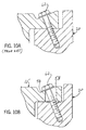
- FIG. 10A is a cross-sectional view showing a prior art inclined side bolt joint
- FIG. 10B is a view similar to FIG. 10A but incorporating an aspect of the invention.
- FIG. 11 is a perspective view of the underarm surface of the joint of FIG. 10 B.
- FIG. 6 shows a typical example of a bearing cap 10 and an aluminum cylinder block 20 cross section in the crankshaft bearing bore 22 area.
- the P/M main bearing cap 10 features an integral dowel 24 on each “foot” 26 , on each side of the main bearing bore portion. Each dowel 24 locates in a precise counterbore 28 in the cylinder block joint face as taught by International Patent Publication No. WO 97/42424.
- Another integral dowel 29 is featured on the underarm surface 14 of the P/M main bearing cap 10 which locates in a counterbore 30 on the shelf surface 32 of the cylinder block 20 .
- the P/M main bearing cap 10 (MBC 10 ) When the P/M main bearing cap 10 (MBC 10 ) is installed into the cylinder block 20 , it may be bolted into position or pressed into position. To simplify the explanation, the latter case is considered, though bolting in place does not alter the stresses, only the sequence of arriving at the same final stress distribution.
- the lower integral dowel 24 When the MBC 10 is pressed into position, the lower integral dowel 24 initially locates the MBC 10 relative to the cylinder block 20 with the tapered conical form, and then “nests” into place in the respective counterbore as taught in International Patent Publication No. WO 97/42424. At the same time, the integral dowel 29 on the underarm of the MBC, engages in the counterbore 30 in the cylinder block shelf 32 .
- the pressing force applied to the MBC 10 may be distributed evenly over the entire surface 42 by using a matching profile on the press-in tool 44 as shown in FIG. 8B, or by using raised pads as shown in the tool 46 in FIG. 8C that press on the bolt seating faces of the main bolt holes and the side bolt holes simultaneously with cut-away relief over the rest of the face 42 profile.
- the total load applied is controlled to approximate the sum of the loads of all the bolts plus an allowance for the resistance of the integral dowels.
- This value is readily calculated or can be directly measured on a hydraulic compression test machine with a prototype setup.
- This load is only used as an approximation to control the press-in stroke.
- the reason for this is that the press-in load can be monitored and arrested when it suddenly exceeds the expected range, when the MBC feet filly contact the block joint face and increase the resistance, thereby altering the slope of the press-in stroke and load curve, signaling the hydraulic load to be arrested and the punch withdrawn.
- FIG. 9 shows this curve schematically, with the gap in inches vs. load.
- the height of the block shelf 32 to joint face 14 is chosen to give a mean clearance of g, as shown in FIG. 4 A.
- a clearance level there has been full insertion of the main bolt integral dowels 24 , 29 such that the feet joint face surfaces 16 are in full contact, as shown in detail in FIG. 4 B.
- the shelf face joint integral dowel 29 is partially engaged and the conical teeth 34 are partially indented and partially compressed, as shown in detail in FIG. 4 B.
- the main bolts 50 and the vertical side bolts 52 are tightened down to the respective specified torque levels, which usually approach the yield stress of the bolts used. This action causes the height of the MBC 10 to reduce under the compressive force of the bolts. Values have been measured in the region of 0.005 inches (0.125 mm).
- the vertical side bolts 52 apply a compressive force to the cantilevered arms 40 of the MBC, so this section has two downward forces acting upon it, the whole body compression from the main bolts 50 plus the local compression from the vertical side bolts 52 .
- the principle adopted is to ensure that the original press-in action causes the MBC 10 to seat into its final bolted position, and upon reinstallation, the integral dowels 29 and the teeth 34 simply nest into their previous positions.
- these values must be known. Investigations and direct tolerance capabilities indicate this range of discrepancy to be in the region of 0.010 inches (0.25 mm). Therefore, the indenting teeth 34 have to accommodate plus or minus half this range, of 0.005 inches (0.125 mm). From experiments using a specially made single version of the integral dowel 29 and teeth 34 array (with two rows of teeth, as opposed to three as shown in FIG. 7 ), it was possible to carry out indentation tests (see FIG. 8 A).
- FIG. 8A illustrates simulated surface 32 after indentation and insertion of an integral dowel. This involved using a hydraulic compression test machine to load the test sample with it bearing against a sample of engine block material. It was then possible to record and plot the graph of pressing load versus gap reduction (which is the combination of teeth indentation and height compression). To ensure accuracy, the load was applied incrementally and removed each time prior to gap measurement. This ensured that elastic recovery was not included in the gap reduction.
- FIG. 9 The result of one such test is shown in FIG. 9 .
- a “large” gap set up would be at 0.035 inches (0.825 mm) and a “small” gap set up at 0.025 inches (0.625 mm).
- the degree of teeth indentation and compression is acceptable for joint integrity as judged by shear force testing at these extremes.
- the basic design taught in the previous example also applies to the splayed design with a single exception. Since the bolt passes through a “slot” instead of a round hole, the integral dowel shape must be changed. This is in the form of a “horseshoe” shape 60 , as shown in FIG. 11 . This shape locates into a counterbore at the end of the slot and ensures precise relocation of the teeth into their respective indentations when the cap is refitted after crankshaft installation. To accommodate the inclined angle of the bolt, the counterbore angle will need to match this when being machined.
- the integral dowel 60 may taper in height as illustrated, or not, or taper in the opposite direction.
Landscapes
- Engineering & Computer Science (AREA)
- General Engineering & Computer Science (AREA)
- Mechanical Engineering (AREA)
- Manufacturing & Machinery (AREA)
- Chemical & Material Sciences (AREA)
- Combustion & Propulsion (AREA)
- Cylinder Crankcases Of Internal Combustion Engines (AREA)
Abstract
Description
Claims (6)
Priority Applications (1)
| Application Number | Priority Date | Filing Date | Title |
|---|---|---|---|
| US09/698,671 US6471406B1 (en) | 1996-05-03 | 2000-10-27 | Side-bolt bearing caps |
Applications Claiming Priority (5)
| Application Number | Priority Date | Filing Date | Title |
|---|---|---|---|
| US1685296P | 1996-05-03 | 1996-05-03 | |
| US16194399P | 1999-10-28 | 1999-10-28 | |
| US16824599P | 1999-12-01 | 1999-12-01 | |
| US09/527,791 US6422755B1 (en) | 1996-05-03 | 2000-03-17 | Precisely repositioning powder metal components |
| US09/698,671 US6471406B1 (en) | 1996-05-03 | 2000-10-27 | Side-bolt bearing caps |
Related Parent Applications (1)
| Application Number | Title | Priority Date | Filing Date |
|---|---|---|---|
| US09/527,791 Continuation-In-Part US6422755B1 (en) | 1996-05-03 | 2000-03-17 | Precisely repositioning powder metal components |
Publications (1)
| Publication Number | Publication Date |
|---|---|
| US6471406B1 true US6471406B1 (en) | 2002-10-29 |
Family
ID=27486606
Family Applications (1)
| Application Number | Title | Priority Date | Filing Date |
|---|---|---|---|
| US09/698,671 Expired - Lifetime US6471406B1 (en) | 1996-05-03 | 2000-10-27 | Side-bolt bearing caps |
Country Status (1)
| Country | Link |
|---|---|
| US (1) | US6471406B1 (en) |
Cited By (25)
| Publication number | Priority date | Publication date | Assignee | Title |
|---|---|---|---|---|
| US20050139185A1 (en) * | 2003-12-27 | 2005-06-30 | Grennall Darren J. | Internal combustion engine |
| USD519534S1 (en) * | 2003-10-27 | 2006-04-25 | Robert Bosch Gmbh | Cap for a fitting |
| US20070087217A1 (en) * | 2005-10-14 | 2007-04-19 | Wakade Shekhar G | Selectively reinforced powder metal components |
| US7322750B1 (en) * | 2005-11-18 | 2008-01-29 | Ronnie Besselman | Locking engine bearing splay cap |
| EP1808607A4 (en) * | 2004-08-31 | 2008-07-23 | Isuzu Motors Ltd | Journal bearing structure for crankshaft |
| US20090208771A1 (en) * | 2007-05-09 | 2009-08-20 | Thomas Janecek | Powdered metal manufacturing method and devices |
| WO2010022420A1 (en) * | 2008-09-01 | 2010-03-04 | Miba Sinter Austria Gmbh | Bearing cover |
| US20110013862A1 (en) * | 2007-03-06 | 2011-01-20 | Toyota Jidosha Kabushiki Kaisha | Bearing structure for crankshaft |
| CN102297204A (en) * | 2011-07-26 | 2011-12-28 | 奇瑞汽车股份有限公司 | Main bearing cover and main bearing seat fitting structure of engine |
| CN102865305A (en) * | 2011-07-08 | 2013-01-09 | 上海市离心机械研究所有限公司 | Residue removing device for thin oil lubricating bearing seat of horizontal screw centrifuge |
| CN103148086A (en) * | 2011-12-07 | 2013-06-12 | 沃尔沃汽车公司 | A split bearing arrangement and a method of manufacturing a split bearing arrangement |
| CN104121091A (en) * | 2013-04-23 | 2014-10-29 | 斯太尔动力有限责任公司 | Internal combustion engine with V-shaped arrangement air cylinder base, and assembling method thereof |
| US20150055902A1 (en) * | 2012-04-26 | 2015-02-26 | Gkn Sinter Metals, Llc | Main bearing cap with locating feature |
| WO2016030569A1 (en) * | 2014-08-29 | 2016-03-03 | Wärtsilä Finland Oy | System to reduce the fretting in a bolt-joint (especially for a crankshaft-counterweight structure) |
| US20160319874A1 (en) * | 2015-04-28 | 2016-11-03 | Miba Sinter Austria Gmbh | Bearing arrangement |
| GB2538975A (en) * | 2015-06-01 | 2016-12-07 | Jaguar Land Rover Ltd | Apparatus and method of use of apparatus for locating components of a system |
| US9670953B2 (en) * | 2012-11-19 | 2017-06-06 | Gkn Sinter Metals, Llc | Component with deformable pads |
| US9745925B2 (en) | 2016-01-27 | 2017-08-29 | Ford Global Technologies, Llc | Angled fasteners |
| US10012299B2 (en) * | 2015-10-14 | 2018-07-03 | Dana Automotive Systems Group, Llc | Integrated active limited slip differential |
| US20180209472A1 (en) * | 2017-01-24 | 2018-07-26 | Miba Sinter Austria Gmbh | Bearing cover |
| CN109058281A (en) * | 2018-10-09 | 2018-12-21 | 广西玉柴机器股份有限公司 | Axial positioning structure and localization method for thrust main beating cap |
| US10208803B2 (en) * | 2016-06-03 | 2019-02-19 | Miba Sinter Austria Gmbh | Bearing arrangement |
| US10400816B2 (en) * | 2017-09-15 | 2019-09-03 | Miba Sinter Austria Gmbh | Bearing cover |
| US11041528B1 (en) * | 2020-01-08 | 2021-06-22 | Cummins Inc. | Profiled main bearing caps |
| US11242897B2 (en) | 2016-11-01 | 2022-02-08 | Dana Automotive Systems Group, Llc | Coupling assembly having angled fastener holes |
Citations (3)
| Publication number | Priority date | Publication date | Assignee | Title |
|---|---|---|---|---|
| US4037888A (en) * | 1974-01-09 | 1977-07-26 | Daimler-Benz Aktiengesellschaft | Construction of separating surfaces of a split bearing |
| US5733049A (en) * | 1992-05-20 | 1998-03-31 | Nelson Metal Products Corporation | Mated molded parts assembly and method for making same |
| US5775817A (en) * | 1996-11-04 | 1998-07-07 | General Motors Corporation | Fracture process with bore distortion controls |
-
2000
- 2000-10-27 US US09/698,671 patent/US6471406B1/en not_active Expired - Lifetime
Patent Citations (3)
| Publication number | Priority date | Publication date | Assignee | Title |
|---|---|---|---|---|
| US4037888A (en) * | 1974-01-09 | 1977-07-26 | Daimler-Benz Aktiengesellschaft | Construction of separating surfaces of a split bearing |
| US5733049A (en) * | 1992-05-20 | 1998-03-31 | Nelson Metal Products Corporation | Mated molded parts assembly and method for making same |
| US5775817A (en) * | 1996-11-04 | 1998-07-07 | General Motors Corporation | Fracture process with bore distortion controls |
Non-Patent Citations (1)
| Title |
|---|
| Bow-tie or Splayed Cast Iron Main Bearing Cap, Admitted Prior Art. (No date). |
Cited By (42)
| Publication number | Priority date | Publication date | Assignee | Title |
|---|---|---|---|---|
| USD519534S1 (en) * | 2003-10-27 | 2006-04-25 | Robert Bosch Gmbh | Cap for a fitting |
| US7152568B2 (en) * | 2003-12-27 | 2006-12-26 | Ford Global Technologies, Llc | Internal combustion engine |
| US20050139185A1 (en) * | 2003-12-27 | 2005-06-30 | Grennall Darren J. | Internal combustion engine |
| EP1808607A4 (en) * | 2004-08-31 | 2008-07-23 | Isuzu Motors Ltd | Journal bearing structure for crankshaft |
| US20070087217A1 (en) * | 2005-10-14 | 2007-04-19 | Wakade Shekhar G | Selectively reinforced powder metal components |
| US7695823B2 (en) | 2005-10-14 | 2010-04-13 | Gm Global Technology Operations, Inc. | Selectively reinforced powder metal components |
| US7322750B1 (en) * | 2005-11-18 | 2008-01-29 | Ronnie Besselman | Locking engine bearing splay cap |
| US20110013862A1 (en) * | 2007-03-06 | 2011-01-20 | Toyota Jidosha Kabushiki Kaisha | Bearing structure for crankshaft |
| US7989084B2 (en) * | 2007-05-09 | 2011-08-02 | Motor Excellence, Llc | Powdered metal manufacturing method and devices |
| US20090208771A1 (en) * | 2007-05-09 | 2009-08-20 | Thomas Janecek | Powdered metal manufacturing method and devices |
| US20110158569A1 (en) * | 2008-09-01 | 2011-06-30 | Miba Sinter Austria Gmbh | Bearing cover |
| CN102138012A (en) * | 2008-09-01 | 2011-07-27 | 米巴烧结奥地利有限公司 | Bearing cap |
| JP2012501410A (en) * | 2008-09-01 | 2012-01-19 | ミーバ ジンター オーストリア ゲゼルシャフト ミット ベシュレンクテル ハフツング | Bearing cover |
| CN102138012B (en) * | 2008-09-01 | 2013-09-11 | 米巴烧结奥地利有限公司 | Bearing cap and bearing unit |
| US8690439B2 (en) | 2008-09-01 | 2014-04-08 | Miba Sinter Austria Gmbh | Bearing cover |
| WO2010022420A1 (en) * | 2008-09-01 | 2010-03-04 | Miba Sinter Austria Gmbh | Bearing cover |
| CN102865305A (en) * | 2011-07-08 | 2013-01-09 | 上海市离心机械研究所有限公司 | Residue removing device for thin oil lubricating bearing seat of horizontal screw centrifuge |
| CN102865305B (en) * | 2011-07-08 | 2016-03-30 | 上海市离心机械研究所有限公司 | A kind of deslagging device for thin oil lubrication bearing support of decanter centrifuge |
| CN102297204A (en) * | 2011-07-26 | 2011-12-28 | 奇瑞汽车股份有限公司 | Main bearing cover and main bearing seat fitting structure of engine |
| CN103148086B (en) * | 2011-12-07 | 2015-10-28 | 沃尔沃汽车公司 | The method of split bearing device and manufacture split bearing device |
| CN103148086A (en) * | 2011-12-07 | 2013-06-12 | 沃尔沃汽车公司 | A split bearing arrangement and a method of manufacturing a split bearing arrangement |
| US20150055902A1 (en) * | 2012-04-26 | 2015-02-26 | Gkn Sinter Metals, Llc | Main bearing cap with locating feature |
| US9273733B2 (en) * | 2012-04-26 | 2016-03-01 | Gkn Sinter Metals, Llc | Main bearing cap with locating feature |
| US9528555B2 (en) | 2012-04-26 | 2016-12-27 | Gkn Sinter Metals, Llc | Main bearing cap with locating feature |
| CN104246245B (en) * | 2012-04-26 | 2017-06-06 | Gkn烧结金属有限公司 | Main bearing caps with locating features |
| US9670953B2 (en) * | 2012-11-19 | 2017-06-06 | Gkn Sinter Metals, Llc | Component with deformable pads |
| CN104121091A (en) * | 2013-04-23 | 2014-10-29 | 斯太尔动力有限责任公司 | Internal combustion engine with V-shaped arrangement air cylinder base, and assembling method thereof |
| CN104121091B (en) * | 2013-04-23 | 2018-08-21 | 斯太尔动力有限责任公司 | The internal combustion engine and its assemble method of air cylinder base are arranged with V-type |
| WO2016030569A1 (en) * | 2014-08-29 | 2016-03-03 | Wärtsilä Finland Oy | System to reduce the fretting in a bolt-joint (especially for a crankshaft-counterweight structure) |
| US20160319874A1 (en) * | 2015-04-28 | 2016-11-03 | Miba Sinter Austria Gmbh | Bearing arrangement |
| US9689432B2 (en) * | 2015-04-28 | 2017-06-27 | Miba Sinter Austria Gmbh | Bearing arrangement |
| GB2538975B (en) * | 2015-06-01 | 2018-04-04 | Jaguar Land Rover Ltd | Bearing cap having positioning projections. |
| US20180149110A1 (en) * | 2015-06-01 | 2018-05-31 | Jaguar Land Rover Limited | Apparatus and method of use of apparatus for locating components of a system |
| GB2538975A (en) * | 2015-06-01 | 2016-12-07 | Jaguar Land Rover Ltd | Apparatus and method of use of apparatus for locating components of a system |
| US10012299B2 (en) * | 2015-10-14 | 2018-07-03 | Dana Automotive Systems Group, Llc | Integrated active limited slip differential |
| US9745925B2 (en) | 2016-01-27 | 2017-08-29 | Ford Global Technologies, Llc | Angled fasteners |
| US10208803B2 (en) * | 2016-06-03 | 2019-02-19 | Miba Sinter Austria Gmbh | Bearing arrangement |
| US11242897B2 (en) | 2016-11-01 | 2022-02-08 | Dana Automotive Systems Group, Llc | Coupling assembly having angled fastener holes |
| US20180209472A1 (en) * | 2017-01-24 | 2018-07-26 | Miba Sinter Austria Gmbh | Bearing cover |
| US10400816B2 (en) * | 2017-09-15 | 2019-09-03 | Miba Sinter Austria Gmbh | Bearing cover |
| CN109058281A (en) * | 2018-10-09 | 2018-12-21 | 广西玉柴机器股份有限公司 | Axial positioning structure and localization method for thrust main beating cap |
| US11041528B1 (en) * | 2020-01-08 | 2021-06-22 | Cummins Inc. | Profiled main bearing caps |
Similar Documents
| Publication | Publication Date | Title |
|---|---|---|
| US6471406B1 (en) | Side-bolt bearing caps | |
| US6422755B1 (en) | Precisely repositioning powder metal components | |
| EP0897485B1 (en) | Precisely repositionable bearing cap | |
| US5716145A (en) | Process for fracture separating the bearing cover of a multi-part bearing arrangement, particularly, in crankcases of internal-combustion engines | |
| US5072655A (en) | Pistons for axial piston machines | |
| EP1075605B1 (en) | Split bearing arrangement in a machine housing, especially a crankshaft sliding bearing for reciprocating piston machines | |
| US5279268A (en) | Piston assembly with distributed loading and centrally fastened wrist pin | |
| EP1382866A2 (en) | Connecting rod with a split rod-eye | |
| JP6416105B2 (en) | Assembly crankshaft and method of manufacturing assembly crankshaft | |
| JPH09126223A (en) | Crankshaft bearing device for internal combustion engine | |
| Hamer et al. | Particle deformation and counterface damage when relatively soft particles are squashed between hard anvils | |
| JPH1172113A (en) | Method of manufacturing bearing arrangement and bearing arrangement produced thereby | |
| US8613137B2 (en) | Connecting rod lubrication recess | |
| US6874229B2 (en) | Connecting rod with ellipitical opening and method for production | |
| Ilia et al. | Benchmarking the industry: powder forging makes a better connecting rod | |
| EP0271638A2 (en) | Cast shaft, in particular camshaft | |
| KR100632167B1 (en) | Bearing | |
| US7250070B2 (en) | Fractured powder metal connecting rod and a method of manufacturing the same | |
| DE102004024576A1 (en) | Connecting rod for an I.C. engine comprises connecting rod eyes having a cross-section which deviates from a circular or cylindrical shape | |
| DE69930779T2 (en) | Sliding part for a sliding device | |
| JPH07100712A (en) | Manufacturing method of aluminum alloy connecting rod | |
| DE102009036784A1 (en) | Bore profile for a piston pin bearing | |
| Fukuoka | Analysis of the tightening process of bolted joint with a tensioner: effects of interface stiffness | |
| DE102015217023A1 (en) | Cylinder liner for an internal combustion engine, internal combustion engine with such a cylinder liner and method for producing a cylinder liner for an internal combustion engine | |
| Robinson | The design and development of pistons for automobile engines |
Legal Events
| Date | Code | Title | Description |
|---|---|---|---|
| AS | Assignment |
Owner name: GKN SINTER METALS - GERMANTOWN, INC., WISCONSIN Free format text: ASSIGNMENT OF ASSIGNORS INTEREST;ASSIGNORS:CADLE, TERRY M.;BUTLER, PETER C.;MANDEL, JOEL H.;REEL/FRAME:011659/0178;SIGNING DATES FROM 20010301 TO 20010305 |
|
| AS | Assignment |
Owner name: GKN SINTER METALS, INC., WISCONSIN Free format text: MERGER;ASSIGNOR:GKN SINTER METALS - GERMANTOWN, INC.;REEL/FRAME:013056/0158 Effective date: 20010730 |
|
| STCF | Information on status: patent grant |
Free format text: PATENTED CASE |
|
| FPAY | Fee payment |
Year of fee payment: 4 |
|
| AS | Assignment |
Owner name: GKN SINTER METALS, LLC, MICHIGAN Free format text: CONVERSION;ASSIGNOR:GKN SINTER METALS, INC.;REEL/FRAME:022449/0460 Effective date: 20080917 Owner name: GKN SINTER METALS, LLC,MICHIGAN Free format text: CONVERSION;ASSIGNOR:GKN SINTER METALS, INC.;REEL/FRAME:022449/0460 Effective date: 20080917 |
|
| FPAY | Fee payment |
Year of fee payment: 8 |
|
| FPAY | Fee payment |
Year of fee payment: 12 |