US645989A - Plow attachment. - Google Patents
Plow attachment. Download PDFInfo
- Publication number
- US645989A US645989A US74175699A US1899741756A US645989A US 645989 A US645989 A US 645989A US 74175699 A US74175699 A US 74175699A US 1899741756 A US1899741756 A US 1899741756A US 645989 A US645989 A US 645989A
- Authority
- US
- United States
- Prior art keywords
- colter
- arm
- frame
- plow
- trail
- Prior art date
- Legal status (The legal status is an assumption and is not a legal conclusion. Google has not performed a legal analysis and makes no representation as to the accuracy of the status listed.)
- Expired - Lifetime
Links
Images
Classifications
-
- A—HUMAN NECESSITIES
- A01—AGRICULTURE; FORESTRY; ANIMAL HUSBANDRY; HUNTING; TRAPPING; FISHING
- A01B—SOIL WORKING IN AGRICULTURE OR FORESTRY; PARTS, DETAILS, OR ACCESSORIES OF AGRICULTURAL MACHINES OR IMPLEMENTS, IN GENERAL
- A01B17/00—Ploughs with special additional arrangements, e.g. means for putting manure under the soil, clod-crushers ; Means for breaking the subsoil
Definitions
- My invention is an improved revolving colter attachment for turning-plows, the object of my invention being to provide a revolving colter adapted for cutting through stalks, weeds, stubble, and other trash in advance of the plow, thereby clearing away obstructions, increasing the efficiency of the plow,
- a further object of my invention is to provide an improved revolving colter and actuating mechanism therefor adapted to be attached to any ordinary turning-plow and to operate in conjunction therewith.
- my invention consists in the combination, with a relatively-fixed blade or cutter-arm, of a revoluble serrated colter having a support adapted'to be attached to and readily removed from a plow.
- My invention further consists in the combination, Wllill't longitudinally-movable cutter-arm, of a tension-spring to extend said arm anda support for said arm and spring.
- My invention further consists in the coinbination, with a case or frame having radial arms adapted to be secured to a plow-beam, of a revoluble colter mounted in said frame or case, a trail-frame hinged on the axle of the colter, a traction-wheel mounted in said trailframe, and connections between said tractionwheel and said colter to revolve the latter when the plow moves.
- My invention further consists in the peculiar construction and combination of devices hereinafter fully set forth and particularly pointed out in the claims.
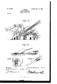
- Figure 1 is a landside elevation of an ordinary turningplow provided with my improved colter attachment.
- Fig. 2 is a horizontal sectional view of the same.
- Fig. 3 is arear end elevation of my improved attachment, showing the same in operative position on. a plow.
- Fig. 4 is a detail view of the longitudinally movable cutter-arm.
- 1 represents a frame-plate of suitable form having integral radial arms 2 arranged at a suitable angle and which are adapted to be secured to the beam a. of a common turning-plow by the usual clip or U-shaped bolts Z), said arms and said bolts admitting of the ready attachment of the frame-plate to the plow and of its adjustment thereon.
- -On the lower side of the frame-plate is a downwardly inclined forwardly extending socket-arm 3, in which is secured the upper end of a cutter arm or bar 4, connected thereto and adapted to play therein by an adjusting-slot 5 and adj ust-ing-bolts 6.
- a tensionspring 7 bears against the upper portion of said cutter-arm and keeps the latter normally supported at the outer limitof its movement with relation to the plate-frame.
- a knife or cutter 11 is secured and depends from the frameplate in line with the landside surface of the plow and at a slight distance in advance of the cutting edge thereof.
- the outer side of the revolving colter 1O bears against the proximate surface of the frame-plate, and on the inner side of said revolving colter is a double gear 12, which may be either attached thereto or formed integrally therewith.
- a trail-frame 13 On the axle or colter-shaft 9 is hinged or pivoted the front end of a trail-frame 13, which is made of a single piece of bar metal bent to form the longitudinal arm 14:, having the lateral offset 15 near'its front end and the downturned arm 16 at its rear end, which said arm 16 is bent to form a horizontal lateral offset 17 and the upturned vertical arm or standard 18, which is abreast of and parallel With the arm 16.
- a driving-shaft 19 is mounted in bearings formed in the arms 16 18, near the lower ends thereof, and on said shaft is a traction-wheel 20, which is adapted to run in rear of the plowshare. in the furrow and on the inner side of the landside and to rotate by frictional contact with the bottom of the furrow.
- spur or other suitable gear-wheel 21 rotates with the traction-wheel and engages a pinion 22 on a shaft 23, which is mounted in bearings near the upper ends-of the arms 16 18 and is provided on its landside end with a beveled gear 24, which engages a similar gear 25 ona connecting-shaft 26, which is mounted in a bearing 27 on one side of the arm 14 of the trail-frame and in a bearing 28 in the offset 15.
- a beveled gear 29 To the front end of the shaft 26 is fixed a beveled gear 29, which engages the gear 12 on the revolving colter.
- end of the trail-frame is adapted to play vertically when the plow is in motion by reason of the hinged connection of the trail-frame to the axle of the revolving colter, thus avoiding torsional and other stress on the trailframe and enabling the traction-wheel to ride over rocks, roots,and other obstructions which may be encountered in the furrow without disconnecting the revoluble colter or pretermitting the rotation of said colter.
- a vertical guiding and retaining yoke 30 which is formed from a single bar of metal and is bolted to the plow-standard c, on thelandside thereof, as at 31, the arm 14 of the trail-frame being disposed between the proximate sides of the said yoke and the plow-standard.
- a spring 32 is firmly bolted at its inner end to the upper end of the yoke 30, and the lower rear end of said spring is connected to the arm 14 of the trail-frame, as at 33, said spring bearing downwardly on said trail-frame and exerting downward pressure on the traction-wheel sufficient to insure the rotation of the latter in contact with the bottom of the furrow.
- a suitable case 34 which is indicated in dotted lines, Figs. 1 and 3, incloses the connecting actuating mechanism between the traction-wheel and the revoluble colter to excl ude grit therefrom and shield the same from injury.
- I claim- 1 In a plow attachment, the combination, with the colter case or frame, having the radial arms adapted to be secured to a plowbeam, of the revoluble colter, in said case or frame, the trail-frame hinged on the axle of the colter, the traction-wheel mounted in said trail-frame, and connections between said traction-wheel and said colter, to revolve th latter, substantially as described.
- the longitudinally-movable cutter-arm in combination with a tension-spring, to extend said arm, and a support for said arm and spring, substantially as described.
- the supporting case or frame adapted to be seen red to a plow, and having a downwardly-inclined arm, in
- the trail-frame formed of a single bar of material, and comprising the longitudinal arm 14, having the offset 28, and the downturned arm 16 bent to form the lateral offset 17 and vertical arm 18, for the purpose set forth, substantially as described.
Description
No. 645,989. Patented Mar. 27, I900. 6. WILSON.
PLOW ATTACHMENT.
(Application filed Dec. 27. 1899.).
(No Model.)
NI'TED TATgES PLOW ATT.ACHM ENT.
SPECIFICATION forming part of Letters Patent No. 645,989, dated March 27, 1900.
Application filed December 27. 1899. Serial No. 741,756. (No model.)
To all whom it may concern:
Be it known that I, CAESAR WILSON, a citizen of the United States, residing at Litchfield, in the county of Meeker and State of Minnesota, have invented anew and useful Plow Attachment, of which the following is a specification.
My invention is an improved revolving colter attachment for turning-plows, the object of my invention being to provide a revolving colter adapted for cutting through stalks, weeds, stubble, and other trash in advance of the plow, thereby clearing away obstructions, increasing the efficiency of the plow,
reducing the draft thereof, and the labor of,
the plowman.
A further object of my invention-is to provide an efficient actuating mechanism of simple construction for revolving the colter.
A further object of my invention is to provide an improved revolving colter and actuating mechanism therefor adapted to be attached to any ordinary turning-plow and to operate in conjunction therewith.
To these ends my invention consists in the combination, with a relatively-fixed blade or cutter-arm, of a revoluble serrated colter having a support adapted'to be attached to and readily removed from a plow.
My invention further consists in the combination, Wllill't longitudinally-movable cutter-arm, of a tension-spring to extend said arm anda support for said arm and spring.
My invention further consists in the coinbination, with a case or frame having radial arms adapted to be secured to a plow-beam, of a revoluble colter mounted in said frame or case, a trail-frame hinged on the axle of the colter, a traction-wheel mounted in said trailframe, and connections between said tractionwheel and said colter to revolve the latter when the plow moves.
My invention further consists in the peculiar construction and combination of devices hereinafter fully set forth and particularly pointed out in the claims.
In the accompanying drawings, Figure 1 is a landside elevation of an ordinary turningplow provided with my improved colter attachment. Fig. 2 is a horizontal sectional view of the same. Fig. 3 is arear end elevation of my improved attachment, showing the same in operative position on. a plow.
. Fig. 4 is a detail view of the longitudinally movable cutter-arm.
In the embodiment of my invention herein shown, 1 represents a frame-plate of suitable form having integral radial arms 2 arranged at a suitable angle and which are adapted to be secured to the beam a. of a common turning-plow by the usual clip or U-shaped bolts Z), said arms and said bolts admitting of the ready attachment of the frame-plate to the plow and of its adjustment thereon. -On the lower side of the frame-plate is a downwardly inclined forwardly extending socket-arm 3, in which is secured the upper end of a cutter arm or bar 4, connected thereto and adapted to play therein by an adjusting-slot 5 and adj ust-ing-bolts 6. A tensionspring 7 bears against the upper portion of said cutter-arm and keeps the latter normally supported at the outer limitof its movement with relation to the plate-frame. A cover-plate Sis bolted on the outer side of the frame-plate 1, and in central openings in said frame-plate and cover-plate is journaled a shaft or axle 9, on which isarevoluble circular colter 10, provided with a serrated or other suitable cutting edge. A knife or cutter 11 is secured and depends from the frameplate in line with the landside surface of the plow and at a slight distance in advance of the cutting edge thereof. The outer side of the revolving colter 1O bears against the proximate surface of the frame-plate, and on the inner side of said revolving colter is a double gear 12, which may be either attached thereto or formed integrally therewith.
On the axle or colter-shaft 9 is hinged or pivoted the front end of a trail-frame 13, which is made of a single piece of bar metal bent to form the longitudinal arm 14:, having the lateral offset 15 near'its front end and the downturned arm 16 at its rear end, which said arm 16 is bent to form a horizontal lateral offset 17 and the upturned vertical arm or standard 18, which is abreast of and parallel With the arm 16.
A driving-shaft 19 is mounted in bearings formed in the arms 16 18, near the lower ends thereof, and on said shaft is a traction-wheel 20, which is adapted to run in rear of the plowshare. in the furrow and on the inner side of the landside and to rotate by frictional contact with the bottom of the furrow. A
spur or other suitable gear-wheel 21 rotates with the traction-wheel and engages a pinion 22 on a shaft 23, which is mounted in bearings near the upper ends-of the arms 16 18 and is provided on its landside end with a beveled gear 24, which engages a similar gear 25 ona connecting-shaft 26, which is mounted in a bearing 27 on one side of the arm 14 of the trail-frame and in a bearing 28 in the offset 15. To the front end of the shaft 26 is fixed a beveled gear 29, which engages the gear 12 on the revolving colter.
It will be understood from the foregoing that when the plow travels in its furrow rotary motion from the traction-wheel will be communicated through the connecting actuating-gear mechanism to the revolving colter and the latter will cut and saw through the weeds, grass, stalks, stubble, and other trash in front of the plow, said obstructions being fed to said revolving colter by the arm 4 and held by said arm against the cutting edge of the colter while the latter cuts through the same.
It will be further understood from the fore-- cheaply manufactured. Moreover, the rear,
end of the trail-frame is adapted to play vertically when the plow is in motion by reason of the hinged connection of the trail-frame to the axle of the revolving colter, thus avoiding torsional and other stress on the trailframe and enabling the traction-wheel to ride over rocks, roots,and other obstructions which may be encountered in the furrow without disconnecting the revoluble colter or pretermitting the rotation of said colter.
The tension-springs 7, while keeping the arm 4 normally extended under tension sufiicient to cause the arm to gatherand direct the trash to the cutting edge of the revolving colter, adapts said arm 4 to yield and move upward in its socket or guide-holder when it encounters an obstruction of unusual size and not adapted to be cut by the revolving colter and to clear said obstruction and permit the same to be acted upon and cut or broken by the rigid cutter 1.1 in rear of said arm or cutter 4.
In order to provide against lateral motion of the trail-frame, I employ a vertical guiding and retaining yoke 30, which is formed from a single bar of metal and is bolted to the plow-standard c, on thelandside thereof, as at 31, the arm 14 of the trail-frame being disposed between the proximate sides of the said yoke and the plow-standard. A spring 32 is firmly bolted at its inner end to the upper end of the yoke 30, and the lower rear end of said spring is connected to the arm 14 of the trail-frame, as at 33, said spring bearing downwardly on said trail-frame and exerting downward pressure on the traction-wheel sufficient to insure the rotation of the latter in contact with the bottom of the furrow.
A suitable case 34, which is indicated in dotted lines, Figs. 1 and 3, incloses the connecting actuating mechanism between the traction-wheel and the revoluble colter to excl ude grit therefrom and shield the same from injury.
Having thus described my invention, I claim- 1. In a plow attachment, the combination, with the colter case or frame, having the radial arms adapted to be secured to a plowbeam, of the revoluble colter, in said case or frame, the trail-frame hinged on the axle of the colter, the traction-wheel mounted in said trail-frame, and connections between said traction-wheel and said colter, to revolve th latter, substantially as described.
2. In a plow-colter,the longitudinally-movable cutter-arm, in combination with a tension-spring, to extend said arm, and a support for said arm and spring, substantially as described.
3. In a plow attachment, the combination with a relatively-fixed guiding-arm, orcutterbar, of a revoluble colter and means to rotate said colter, substantially as described.
4. In a plow attachment, the supporting case or frame, adapted to be seen red to a plow, and having a downwardly-inclined arm, in
combination with a revoluble colter mounted I in said case or frame, and a traction device,
and connections to rotate said colter, substantially as described.
5. The combination, with the case orframe, adapted to be secured to a plow, and having the revolving colter, of the trail-frame connected to said colter case or frame, and having the traction device, and connections to rotate the colter, substantially as described.
6. In a plow attachment, the combination, with the colter case or frame, of the revolving colter supported therein, the trail-frame, the traction and connecting actuating devices to rotate the colter, and the spring, or equivalent device, bearing downward on said trailframe for the purpose set forth, substantially as described.
7. In a plow attachment, the trail-frame, formed of a single bar of material, and comprising the longitudinal arm 14, having the offset 28, and the downturned arm 16 bent to form the lateral offset 17 and vertical arm 18, for the purpose set forth, substantially as described.
8. In a plow attachment, in combination with a supporting frame or case, having the yielding cutter bar or arm 4, and the rigid cutter 11, in rear thereof, the revoluble colter in said support or frame, and means to rotate said colter, substantially as described.
In testimony that I claim the foregoing as my own I have hereto aflixed my signature in the presence of two witnesses.
CAESAR WILSON. Witnesses:
E. HAMME, LARS WILsoN.
Priority Applications (1)
| Application Number | Priority Date | Filing Date | Title |
|---|---|---|---|
| US74175699A US645989A (en) | 1899-12-27 | 1899-12-27 | Plow attachment. |
Applications Claiming Priority (1)
| Application Number | Priority Date | Filing Date | Title |
|---|---|---|---|
| US74175699A US645989A (en) | 1899-12-27 | 1899-12-27 | Plow attachment. |
Publications (1)
| Publication Number | Publication Date |
|---|---|
| US645989A true US645989A (en) | 1900-03-27 |
Family
ID=2714564
Family Applications (1)
| Application Number | Title | Priority Date | Filing Date |
|---|---|---|---|
| US74175699A Expired - Lifetime US645989A (en) | 1899-12-27 | 1899-12-27 | Plow attachment. |
Country Status (1)
| Country | Link |
|---|---|
| US (1) | US645989A (en) |
Cited By (2)
| Publication number | Priority date | Publication date | Assignee | Title |
|---|---|---|---|---|
| US2886113A (en) * | 1955-06-27 | 1959-05-12 | Deere & Co | Center drive rod weeder |
| US3628611A (en) * | 1969-06-09 | 1971-12-21 | Gaynor Carlson | Trash-clearing apparatus |
-
1899
- 1899-12-27 US US74175699A patent/US645989A/en not_active Expired - Lifetime
Cited By (2)
| Publication number | Priority date | Publication date | Assignee | Title |
|---|---|---|---|---|
| US2886113A (en) * | 1955-06-27 | 1959-05-12 | Deere & Co | Center drive rod weeder |
| US3628611A (en) * | 1969-06-09 | 1971-12-21 | Gaynor Carlson | Trash-clearing apparatus |
Similar Documents
| Publication | Publication Date | Title |
|---|---|---|
| US657411A (en) | Stalk-cutter. | |
| US645989A (en) | Plow attachment. | |
| US976329A (en) | Stalk-cutter. | |
| US606412A (en) | Disk plow | |
| US757425A (en) | Beet-harvester. | |
| US757994A (en) | Sulky lister-plow. | |
| US876664A (en) | Cotton chopper and cultivator. | |
| US1233134A (en) | Harvesting-machine. | |
| US1090400A (en) | Stalk-cutter attachment for plows. | |
| US963868A (en) | Beet-harvester. | |
| US1492481A (en) | Machine for eradicating weeds and digging potatoes and the like | |
| US731179A (en) | Disk plow. | |
| US284810A (en) | Plow-colter | |
| US1115425A (en) | Cotton-chopper attachment for cultivators. | |
| US501787A (en) | holsclaw | |
| US1374149A (en) | Machine for picking and cutting cane-straw and plowing under the same | |
| US419333A (en) | Cultivator and cotton-chopper | |
| US1247246A (en) | Cotton-chopper. | |
| US941230A (en) | Cotton-chopper. | |
| US353398A (en) | Stalk-cutter | |
| US624829A (en) | Cotton chopper and cultivator | |
| US715320A (en) | Beet-harvesting plow. | |
| US942294A (en) | Cotton-chopper. | |
| US1005792A (en) | Cotton-chopper. | |
| US1088257A (en) | Stalk-cutter. |