US6458446B1 - Thermoplastic sheet with textured surface for use in composite layered product with interlocking interface and method thereof - Google Patents
Thermoplastic sheet with textured surface for use in composite layered product with interlocking interface and method thereof Download PDFInfo
- Publication number
- US6458446B1 US6458446B1 US09/396,818 US39681899A US6458446B1 US 6458446 B1 US6458446 B1 US 6458446B1 US 39681899 A US39681899 A US 39681899A US 6458446 B1 US6458446 B1 US 6458446B1
- Authority
- US
- United States
- Prior art keywords
- sheet
- rubbers
- protuberances
- copolymers
- thermoplastic material
- Prior art date
- Legal status (The legal status is an assumption and is not a legal conclusion. Google has not performed a legal analysis and makes no representation as to the accuracy of the status listed.)
- Expired - Lifetime
Links
Images

Classifications
-
- B—PERFORMING OPERATIONS; TRANSPORTING
- B32—LAYERED PRODUCTS
- B32B—LAYERED PRODUCTS, i.e. PRODUCTS BUILT-UP OF STRATA OF FLAT OR NON-FLAT, e.g. CELLULAR OR HONEYCOMB, FORM
- B32B3/00—Layered products comprising a layer with external or internal discontinuities or unevennesses, or a layer of non-planar form; Layered products having particular features of form
- B32B3/26—Layered products comprising a layer with external or internal discontinuities or unevennesses, or a layer of non-planar form; Layered products having particular features of form characterised by a particular shape of the outline of the cross-section of a continuous layer; characterised by a layer with cavities or internal voids ; characterised by an apertured layer
- B32B3/30—Layered products comprising a layer with external or internal discontinuities or unevennesses, or a layer of non-planar form; Layered products having particular features of form characterised by a particular shape of the outline of the cross-section of a continuous layer; characterised by a layer with cavities or internal voids ; characterised by an apertured layer characterised by a layer formed with recesses or projections, e.g. hollows, grooves, protuberances, ribs
-
- B—PERFORMING OPERATIONS; TRANSPORTING
- B29—WORKING OF PLASTICS; WORKING OF SUBSTANCES IN A PLASTIC STATE IN GENERAL
- B29C—SHAPING OR JOINING OF PLASTICS; SHAPING OF MATERIAL IN A PLASTIC STATE, NOT OTHERWISE PROVIDED FOR; AFTER-TREATMENT OF THE SHAPED PRODUCTS, e.g. REPAIRING
- B29C37/00—Component parts, details, accessories or auxiliary operations, not covered by group B29C33/00 or B29C35/00
- B29C37/0078—Measures or configurations for obtaining anchoring effects in the contact areas between layers
- B29C37/0082—Mechanical anchoring
-
- B—PERFORMING OPERATIONS; TRANSPORTING
- B29—WORKING OF PLASTICS; WORKING OF SUBSTANCES IN A PLASTIC STATE IN GENERAL
- B29C—SHAPING OR JOINING OF PLASTICS; SHAPING OF MATERIAL IN A PLASTIC STATE, NOT OTHERWISE PROVIDED FOR; AFTER-TREATMENT OF THE SHAPED PRODUCTS, e.g. REPAIRING
- B29C59/00—Surface shaping of articles, e.g. embossing; Apparatus therefor
- B29C59/02—Surface shaping of articles, e.g. embossing; Apparatus therefor by mechanical means, e.g. pressing
-
- B—PERFORMING OPERATIONS; TRANSPORTING
- B32—LAYERED PRODUCTS
- B32B—LAYERED PRODUCTS, i.e. PRODUCTS BUILT-UP OF STRATA OF FLAT OR NON-FLAT, e.g. CELLULAR OR HONEYCOMB, FORM
- B32B25/00—Layered products comprising a layer of natural or synthetic rubber
- B32B25/04—Layered products comprising a layer of natural or synthetic rubber comprising rubber as the main or only constituent of a layer, which is next to another layer of the same or of a different material
- B32B25/08—Layered products comprising a layer of natural or synthetic rubber comprising rubber as the main or only constituent of a layer, which is next to another layer of the same or of a different material of synthetic resin
-
- B—PERFORMING OPERATIONS; TRANSPORTING
- B32—LAYERED PRODUCTS
- B32B—LAYERED PRODUCTS, i.e. PRODUCTS BUILT-UP OF STRATA OF FLAT OR NON-FLAT, e.g. CELLULAR OR HONEYCOMB, FORM
- B32B27/00—Layered products comprising a layer of synthetic resin
- B32B27/30—Layered products comprising a layer of synthetic resin comprising vinyl (co)polymers; comprising acrylic (co)polymers
- B32B27/304—Layered products comprising a layer of synthetic resin comprising vinyl (co)polymers; comprising acrylic (co)polymers comprising vinyl halide (co)polymers, e.g. PVC, PVDC, PVF, PVDF
-
- B—PERFORMING OPERATIONS; TRANSPORTING
- B32—LAYERED PRODUCTS
- B32B—LAYERED PRODUCTS, i.e. PRODUCTS BUILT-UP OF STRATA OF FLAT OR NON-FLAT, e.g. CELLULAR OR HONEYCOMB, FORM
- B32B7/00—Layered products characterised by the relation between layers; Layered products characterised by the relative orientation of features between layers, or by the relative values of a measurable parameter between layers, i.e. products comprising layers having different physical, chemical or physicochemical properties; Layered products characterised by the interconnection of layers
- B32B7/04—Interconnection of layers
- B32B7/12—Interconnection of layers using interposed adhesives or interposed materials with bonding properties
-
- B—PERFORMING OPERATIONS; TRANSPORTING
- B29—WORKING OF PLASTICS; WORKING OF SUBSTANCES IN A PLASTIC STATE IN GENERAL
- B29K—INDEXING SCHEME ASSOCIATED WITH SUBCLASSES B29B, B29C OR B29D, RELATING TO MOULDING MATERIALS OR TO MATERIALS FOR MOULDS, REINFORCEMENTS, FILLERS OR PREFORMED PARTS, e.g. INSERTS
- B29K2023/00—Use of polyalkenes or derivatives thereof as moulding material
- B29K2023/04—Polymers of ethylene
- B29K2023/06—PE, i.e. polyethylene
- B29K2023/0658—PE, i.e. polyethylene characterised by its molecular weight
- B29K2023/0683—UHMWPE, i.e. ultra high molecular weight polyethylene
-
- B—PERFORMING OPERATIONS; TRANSPORTING
- B29—WORKING OF PLASTICS; WORKING OF SUBSTANCES IN A PLASTIC STATE IN GENERAL
- B29K—INDEXING SCHEME ASSOCIATED WITH SUBCLASSES B29B, B29C OR B29D, RELATING TO MOULDING MATERIALS OR TO MATERIALS FOR MOULDS, REINFORCEMENTS, FILLERS OR PREFORMED PARTS, e.g. INSERTS
- B29K2027/00—Use of polyvinylhalogenides or derivatives thereof as moulding material
- B29K2027/12—Use of polyvinylhalogenides or derivatives thereof as moulding material containing fluorine
-
- B—PERFORMING OPERATIONS; TRANSPORTING
- B32—LAYERED PRODUCTS
- B32B—LAYERED PRODUCTS, i.e. PRODUCTS BUILT-UP OF STRATA OF FLAT OR NON-FLAT, e.g. CELLULAR OR HONEYCOMB, FORM
- B32B2327/00—Polyvinylhalogenides
- B32B2327/12—Polyvinylhalogenides containing fluorine
- B32B2327/18—PTFE, i.e. polytetrafluoroethylene
-
- Y—GENERAL TAGGING OF NEW TECHNOLOGICAL DEVELOPMENTS; GENERAL TAGGING OF CROSS-SECTIONAL TECHNOLOGIES SPANNING OVER SEVERAL SECTIONS OF THE IPC; TECHNICAL SUBJECTS COVERED BY FORMER USPC CROSS-REFERENCE ART COLLECTIONS [XRACs] AND DIGESTS
- Y10—TECHNICAL SUBJECTS COVERED BY FORMER USPC
- Y10T—TECHNICAL SUBJECTS COVERED BY FORMER US CLASSIFICATION
- Y10T428/00—Stock material or miscellaneous articles
- Y10T428/17—Three or more coplanar interfitted sections with securing means
-
- Y—GENERAL TAGGING OF NEW TECHNOLOGICAL DEVELOPMENTS; GENERAL TAGGING OF CROSS-SECTIONAL TECHNOLOGIES SPANNING OVER SEVERAL SECTIONS OF THE IPC; TECHNICAL SUBJECTS COVERED BY FORMER USPC CROSS-REFERENCE ART COLLECTIONS [XRACs] AND DIGESTS
- Y10—TECHNICAL SUBJECTS COVERED BY FORMER USPC
- Y10T—TECHNICAL SUBJECTS COVERED BY FORMER US CLASSIFICATION
- Y10T428/00—Stock material or miscellaneous articles
- Y10T428/24—Structurally defined web or sheet [e.g., overall dimension, etc.]
- Y10T428/24174—Structurally defined web or sheet [e.g., overall dimension, etc.] including sheet or component perpendicular to plane of web or sheet
- Y10T428/24182—Inward from edge of web or sheet
-
- Y—GENERAL TAGGING OF NEW TECHNOLOGICAL DEVELOPMENTS; GENERAL TAGGING OF CROSS-SECTIONAL TECHNOLOGIES SPANNING OVER SEVERAL SECTIONS OF THE IPC; TECHNICAL SUBJECTS COVERED BY FORMER USPC CROSS-REFERENCE ART COLLECTIONS [XRACs] AND DIGESTS
- Y10—TECHNICAL SUBJECTS COVERED BY FORMER USPC
- Y10T—TECHNICAL SUBJECTS COVERED BY FORMER US CLASSIFICATION
- Y10T428/00—Stock material or miscellaneous articles
- Y10T428/24—Structurally defined web or sheet [e.g., overall dimension, etc.]
- Y10T428/24479—Structurally defined web or sheet [e.g., overall dimension, etc.] including variation in thickness
- Y10T428/24521—Structurally defined web or sheet [e.g., overall dimension, etc.] including variation in thickness with component conforming to contour of nonplanar surface
-
- Y—GENERAL TAGGING OF NEW TECHNOLOGICAL DEVELOPMENTS; GENERAL TAGGING OF CROSS-SECTIONAL TECHNOLOGIES SPANNING OVER SEVERAL SECTIONS OF THE IPC; TECHNICAL SUBJECTS COVERED BY FORMER USPC CROSS-REFERENCE ART COLLECTIONS [XRACs] AND DIGESTS
- Y10—TECHNICAL SUBJECTS COVERED BY FORMER USPC
- Y10T—TECHNICAL SUBJECTS COVERED BY FORMER US CLASSIFICATION
- Y10T428/00—Stock material or miscellaneous articles
- Y10T428/24—Structurally defined web or sheet [e.g., overall dimension, etc.]
- Y10T428/24479—Structurally defined web or sheet [e.g., overall dimension, etc.] including variation in thickness
- Y10T428/24595—Structurally defined web or sheet [e.g., overall dimension, etc.] including variation in thickness and varying density
- Y10T428/24603—Fiber containing component
-
- Y—GENERAL TAGGING OF NEW TECHNOLOGICAL DEVELOPMENTS; GENERAL TAGGING OF CROSS-SECTIONAL TECHNOLOGIES SPANNING OVER SEVERAL SECTIONS OF THE IPC; TECHNICAL SUBJECTS COVERED BY FORMER USPC CROSS-REFERENCE ART COLLECTIONS [XRACs] AND DIGESTS
- Y10—TECHNICAL SUBJECTS COVERED BY FORMER USPC
- Y10T—TECHNICAL SUBJECTS COVERED BY FORMER US CLASSIFICATION
- Y10T428/00—Stock material or miscellaneous articles
- Y10T428/24—Structurally defined web or sheet [e.g., overall dimension, etc.]
- Y10T428/24628—Nonplanar uniform thickness material
- Y10T428/24669—Aligned or parallel nonplanarities
- Y10T428/24678—Waffle-form
Definitions
- the present invention relates to a method of producing a thermoplastic sheet having a textured surface, the product produced by the method, and the method of using the thermoplastic sheet with textured surface to produce a composite layered product of dissimilar materials with interlocking interface between the layers, and the product produced thereby.
- a process for manufacturing a part including the steps of molding a thermoplastic material into a generally planar sheet form having a textured surface on at least one side with a predetermined pressure between a die and a perforated insert, removing the molded thermoplastic material sheet and perforated insert from the die, and sintering the molded thermoplastic material sheet at a predetermined temperature for a predetermined period of time.
- the textured surface is defined by a plurality of projections or protuberances with at least one side wall extending outwardly from the sheet.
- the process can also include the step of stripping the sintered, molded, thermoplastic material sheet from the perforated insert, masking at least one side of the sintered, molded, thermoplastic material sheet for etching, and/or etching the textured surface of the sintered, molded, thermoplastic material sheet with a sodium-based etchant.
- the process according to the present invention can also include the steps of inserting the sintered, molded, thermoplastic material sheet into a molding die, introducing a dissimilar material into the molding die under pressure, and mechanically interlocking the thermoplastic material sheet to the dissimilar molded material with the plurality of protuberances.
- the mechanical interlocking of the thermoplastic sheet material to the dissimilar molded material is accomplished by deforming the plurality of protuberances during the molding step so that the at least one side wall of the protuberance moves into an angled orientation with respect to the thermoplastic material sheet to define a plurality of individual mechanical locking members along an interface between the thermoplastic material sheet and the dissimilar molded material. A portion of the molded dissimilar material is trapped between the angled side wall of each protuberance and the thermoplastic material sheet is mechanically interlocked along the interface with the dissimilar molded material.
- a part manufactured according to the process of the present invention includes a thermoplastic material molded and sintered into a generally planar sheet form having a textured surface on at least one side.
- the textured surface is defined by a plurality of protuberances with at least one side wall extending outwardly from the sheet.
- the plurality of protuberances increases an effective surface area of the thermoplastic material sheet by at least 35%, or preferably by between 35% and 40%, inclusive.
- the protuberances can take any desired form, such as projections having cross sections that are circular, oval, triangular, rectangular, or other multi-sided configurations. Preferably, a circular cross section is provided.
- the part manufactured according to the process of the present invention can also include a dissimilar material layer molded to the textured surface of the sheet with a mechanically locked interface between the dissimilar material layer and the sheet as a result of deformation of the protuberances during the molding process to produce a composite layered product.
- the composite layered product can be used in a wide variety of applications, such as for valve diaphragms, pump diaphragms, bearing pads, or any application where delamination of dissimilar composite layered materials is a problem.
- thermoplastic material used in the process, or in the part can be selected from the group consisting of fluoroplastic polymers, polytetrafluoroethylene (PTFE), fluorinated ethylene propylene (FEP) copolymers, perfluoroalkoxy (PFA) resins, polychlorotrifluoroethylene (PCTFE), ethylene-chlorotrifluoroethylene (ECTFE) copolymers, ethylene-tetrafluoroethylene (ETFE) copolymers, polyvinylidene fluoride (PVDF), polyvinyl fluoride (PVF), ultrahigh-molecular-weight polyethylene (UHMWPE), and mixtures thereof.
- fluoroplastic polymers polytetrafluoroethylene (PTFE), fluorinated ethylene propylene (FEP) copolymers, perfluoroalkoxy (PFA) resins, polychlorotrifluoroethylene (PCTFE), ethylene-chlorotrifluoroethylene (ECTFE) copo
- thermoplastic material used in the process according to the present invention, or in the part can contain as a major constituent material selected from the group consisting of fluoroplastic polymers, polytetrafluoroethylene (PTFE), fluorinated ethylene propylene (FEP) copolymers, perfluoroalkoxy (PFA) resins, polychlorotrifluoroethylene (PCTFE), ethylene-chlorotrifluoroethylene (ECTFE) copolymers, ethylene-tetrafluoroethylene (ETFE) copolymers, polyvinylidene fluoride (PVDF), polyvinyl fluoride (PVF), ultra-high-molecular-weight polyethylene (UHMWPE), and mixtures thereof.
- fluoroplastic polymers polytetrafluoroethylene (PTFE), fluorinated ethylene propylene (FEP) copolymers, perfluoroalkoxy (PFA) resins, polychlorotrifluoroethylene (PCTFE), ethylene-chlor
- the dissimilar material used in the process according to the present invention, or in the part, can be selected from the group consisting of natural rubbers, vulcanized rubbers, butadiene-styrene copolymers, chloroprene polymers, nitrile rubbers, butadiene-acrylonitrile copolymers, isobutylene copolymers, butyl rubbers, polysulfide rubbers, ethylene-propylene rubbers, polyurethane elastomers, silicone rubbers, fluorocarbon elastomers, polyester elastomers, chlorinated rubbers, rubber hydrochloride, cyclized rubbers, chlorosulphonated polyethylene, and mixtures thereof.
- the dissimilar material used in the process according to the present invention, or in the part can contain as a major constituent an elastomer material selected from the group consisting of natural rubbers, vulcanized rubbers, butadiene-styrene copolymers, chloroprene polymers, nitrile rubbers, butadiene-acrylonitrile copolymers, isobutylene copolymers, butyl rubbers, polysulfide rubbers, ethylene-propylene rubbers, polyurethane elastomers, silicone rubbers, fluorocarbon elastomers, polyester elastomers, chlorinated rubbers, rubber hydrochloride, cyclized rubbers, chlorosulphonated polyethylene, and mixtures thereof.
- an elastomer material selected from the group consisting of natural rubbers, vulcanized rubbers, butadiene-styrene copolymers, chloroprene polymers, nitrile rubbers, butadiene-acrylon
- FIG. 2 is a cross sectional detail of the sheet taken as shown in FIG. 1;
- FIG. 3 is a cross sectional detail of the part according to the present invention after molding a dissimilar material layer to the textured surface of the sheet and illustrating a mechanically locked interface between the dissimilar material layer and the thermoplastic material sheet as a result of deformation of the protuberances during the molding process;
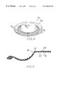
- FIG. 4 is a perspective view of a composite layered product according to the present invention.
- a part 10 according to the present invention is manufactured by a process including the steps of molding a thermoplastic material into a generally planar sheet form having a textured surface 12 on at least one side 14 with a predetermined pressure between a die and a perforated insert, removing the molded thermoplastic material sheet 16 and perforated insert from the die, and sintering the molded thermoplastic material sheet 16 at a predetermined temperature for a predetermined period of time.
- the textured surface 12 is defined by a plurality of projections or protuberances 18 with at least one side wall 20 extending outwardly from the sheet 16 .
- the molding process can also include the steps of gradually increasing pressure on the thermoplastic material sheet 16 between the die and the perforated insert with a first predetermined force, dwelling at the first predetermined force for a first predetermined period of time, and releasing the first predetermined force on the thermoplastic material 16 .
- the process can also include the steps of gradually reapplying increasing pressure on the thermoplastic material sheet 16 between the die and the perforated insert with a second predetermined force, dwelling at the second predetermined force for a second predetermined period of time, and releasing the second predetermined force on the thermoplastic material sheet 16 .
- the process according to the present invention can be performed in a mold press using virgin PTFE.
- the press can subject the thermoplastic material to a molding pressure of approximately 450 tons (1,750 psi hydraulic pressure).
- the perforated metal insert is cleaned in advance of the molding operation.
- the die is also thoroughly cleaned at the beginning of the setup.
- the thermoplastic material fill depth in the die is set to 0.225 inches.
- the die is filled with a powder form of virgin PTFE and the powder is leveled off at the top of the die with a straight edged tool.
- the perforated metal insert is positioned on top of the powder in a center location with respect to the die. The die is moved into the press position.
- Blotter paper is positioned on top of the perforated metal insert, and a solid rubber matting is placed on top of the blotter paper.
- the upper ram is lowered into the press position, and pressure is slowly increased up to approximately 450 tons. After reaching the 450 ton pressure, the pressure is applied for approximately 60 seconds, defining a dwell cycle prior to releasing the pressure. After release of the pressure, the ram is raised away from the solid rubber matting. An additional rubber mat is positioned on top of the solid rubber matting previously positioned on top of the blotter paper.
- the ram is slowly lowered onto the part and pressure is raised back up to approximately 450 tons. After reaching the 450 ton pressure, the pressure is applied for approximately 60 seconds defining a second dwell cycle prior to release of the pressure.
- the ram is raised to the upper position.
- the lower die is moved into an eject position.
- the molded part is removed from the die. Any excess flash is removed from the part with a razor knife.
- the part is placed in a vertical position in a tray for sintering.
- the parts are placed into an oven at approximately 700° F. and are sintered for approximately 1 hour. The parts are removed from the oven.
- the thermoplastic material sheet is stripped off from the perforated metal insert.
- the smooth side of the textured sheet can be masked for subsequent etching with a suitable wash.
- the textured surface of the virgin PTFE thermoplastic material sheet can be etched with a sodium-based etchant.
- thermoplastic material is selected from the group consisting of: fluoroplastic polymers; polytetrafluoroethylene (PTFE); fluorinated ethylene propylene (FEP) copolymers; perfluoroalkoxy (PFA) resins; polychlorotrifluoroethylene (PCTFE); ethylene-chlorotrifluoroethylene (ECTFE) copolymers; ethylene-tetrafluoroethylene (ETFE) copolymers; polyvinylidene fluoride (PVDF); polyvinyl fluoride (PVF); ultrahigh-molecular-weight polyethylene (UHMWPE); and mixtures thereof.
- PTFE polytetrafluoroethylene
- FEP fluorinated ethylene propylene copolymers
- PFA perfluoroalkoxy
- PCTFE polychlorotrifluoroethylene
- ECTFE ethylene-chlorotrifluoroethylene
- ETFE ethylene-tetrafluoroethylene copolymers
- thermoplastic sheet where the thermoplastic material contains as a major constituent a material selected from the group consisting of: fluoroplastic polymers; polytetrafluoroethylene (PTFE); fluorinated ethylene propylene (FEP) copolymers; perfluoroalkoxy (PFA) resins; polychlorotrifluoroethylene (PCTFE); ethylene-chlorotrifluoroethylene (ECTFE) copolymers; ethylene-tetrafluoroethylene (ETFE) copolymers; polyvinylidene fluoride (PVDF); polyvinyl fluoride (PVF); ultrahigh-molecular-weight polyethylene (UHMWPE); and mixtures thereof.
- PTFE polytetrafluoroethylene
- FEP fluorinated ethylene propylene copolymers
- PFA perfluoroalkoxy
- PCTFE polychlorotrifluoroethylene
- ECTFE ethylene-chlorotrifluoroethylene
- ETFE ethylene-
- each protuberance has at least one side wall 20 extending outwardly in a direction generally perpendicular to the planar sheet 16 .
- the protuberances 18 can be disposed in a predetermined geometric pattern, or can be randomly placed on the surface of the planar sheet 16 .
- the protuberances 18 are disposed in a predetermined geometric pattern.
- the cross section configuration of the protuberances 18 can be consistent throughout the textured surface 12 of the sheet 16 , or can be varied across the textured surface 12 of the planar sheet 16 as desired for any particular application.
- the protuberances 18 increase an effective surface area of the thermoplastic material sheet 16 by at least 35%, and most preferably increases an effective surface area by between 35% and 40%, inclusive.
- the cross sectional area of the protuberances can be the same throughout the textured surface 12 of the sheet 16 , or can be varied across the textured surface 12 of the planar sheet 16 as desired for any particular application.
- the process according to the present invention can also include the step of deforming the plurality of protuberances 18 on the thermoplastic material sheet 16 during molding of the dissimilar material, such that at least one side wall 20 of the protuberances 18 moves into an angled orientation with respect to the thermoplastic material sheet 16 to provide a plurality of individual mechanical locking members 22 along an interface between the thermoplastic material sheet 16 and the dissimilar molded material 24 as best seen in FIG. 3 .
- the deformation of the protuberances 18 traps a portion of the molded dissimilar material 24 between the at least one side wall 20 of each protuberance 18 and the thermoplastic material sheet 16 to mechanically interlock the two materials along an interface disposed therebetween.
- the deformation of the protuberances 18 can define an enlarged outer portion 26 connected to the thermoplastic material sheet 16 with a smaller cross sectional area portion 28 of the protuberance 18 .
- a virgin PTFE thermoplastic material sheet 16 can be inserted into a molding die, where a dissimilar material is introduced into the die under pressure.
- the plurality of protuberances 18 on the virgin PTFE plastic sheet 16 are deformed during the molding process, so that the at least one side wall 20 is deformed to trap a portion of the molded dissimilar material 24 between the protuberance 18 and the sheet 16 , thereby mechanically locking the two materials along an interface disposed therebetween.
- the product formed can be used as a diaphragm in valve and/or pump applications, as a bearing pad, or in any other application where dissimilar materials present delamination problems.
- the dissimilar material molded with the virgin PTFE sheet 16 can be a natural or synthetic rubber suitable for use as a pump diaphragm as illustrated in FIGS. 4 and 5.
- Testing has shown that adhesively or chemically bonded pump diaphragms of virgin PTFE and rubber have an average service life of approximately eight hundred thousand (800,000) to one million (1,000,000) cycles.
- a pump diaphragm product manufactured according to the present invention with virgin PTFE mechanically interlocked to rubber, has successfully completed over four million five hundred thousand (4,500,000) cycles without failure.
- the method and product according to the present invention is capable of dramatically increasing service life of composite layered material products.
- dissimilar materials can be used for molding with the planar sheet, where the dissimilar material is selected from the group consisting of natural rubbers; vulcanized rubbers, butadiene-styrene copolymers, chloroprene polymers; nitrile rubbers; butadiene-acrylonitrile copolymers; isobutylene copolymers; butyl rubbers, polysulfide rubbers; ethylene-propylene rubbers; polyurethane elastomers, silicone rubbers, fluorocarbon elastomers; polyester elastomers; chlorinated rubbers; rubber hydrochloride; cyclized rubbers; chlorosulphonated polyethylene; and mixtures thereof.
- the dissimilar material is selected from the group consisting of natural rubbers; vulcanized rubbers, butadiene-styrene copolymers, chloroprene polymers; nitrile rubbers; butadiene-acrylonitrile copolymers; isobutylene copo
- the following dissimilar materials can also be used for molding with the planar sheet 16 , where the dissimilar material contains as a major constituent an elastomer material selected from the group consisting of natural rubbers; vulcanized rubbers; butadiene-styrene copolymers; chloroprene polymers; nitrile rubbers; butadiene-acrylonitrile copolymers; isobutylene copolymers; butyl rubbers; polysulfide rubbers, ethylene-propylene rubbers, polyurethane elastomers; silicone rubbers; fluorocarbon elastomers; polyester elastomers; chlorinated rubbers; rubber hydrochloride; cyclized rubbers; chlorosulphonated polyethylene; and mixtures thereof.
- an elastomer material selected from the group consisting of natural rubbers; vulcanized rubbers; butadiene-styrene copolymers; chloroprene polymers; nitrile rubbers; buta
Abstract
Description
Claims (32)
Priority Applications (1)
| Application Number | Priority Date | Filing Date | Title |
|---|---|---|---|
| US09/396,818 US6458446B1 (en) | 1999-09-14 | 1999-09-14 | Thermoplastic sheet with textured surface for use in composite layered product with interlocking interface and method thereof |
Applications Claiming Priority (1)
| Application Number | Priority Date | Filing Date | Title |
|---|---|---|---|
| US09/396,818 US6458446B1 (en) | 1999-09-14 | 1999-09-14 | Thermoplastic sheet with textured surface for use in composite layered product with interlocking interface and method thereof |
Publications (1)
| Publication Number | Publication Date |
|---|---|
| US6458446B1 true US6458446B1 (en) | 2002-10-01 |
Family
ID=23568736
Family Applications (1)
| Application Number | Title | Priority Date | Filing Date |
|---|---|---|---|
| US09/396,818 Expired - Lifetime US6458446B1 (en) | 1999-09-14 | 1999-09-14 | Thermoplastic sheet with textured surface for use in composite layered product with interlocking interface and method thereof |
Country Status (1)
| Country | Link |
|---|---|
| US (1) | US6458446B1 (en) |
Cited By (11)
| Publication number | Priority date | Publication date | Assignee | Title |
|---|---|---|---|---|
| US20020172803A1 (en) * | 2001-05-21 | 2002-11-21 | Delusky Arthur K. | Molded article and process for preparing same |
| US6748848B1 (en) * | 2002-12-11 | 2004-06-15 | Gits Manufacturing Company, Llc | Waste gate valve actuator |
| US20040117265A1 (en) * | 2002-12-12 | 2004-06-17 | Paul Hoffman | Method and system for labeling and managing the sale of manufactured concrete blocks |
| WO2005042244A1 (en) * | 2003-10-31 | 2005-05-12 | Pirelli Pneumatici S.P.A. | An expandable bladder for tyre manufacturing apparatuses, a manufacturing method thereof and a process for manufacturing tyres for vehicle wheels |
| US20050173002A1 (en) * | 2003-11-05 | 2005-08-11 | Simendinger William H. | Fiber-reinforced polymer (FRP) valve body with a polymeric liner and method of manufacturing same |
| WO2006046259A1 (en) * | 2004-10-27 | 2006-05-04 | Pirelli Tyre S.P.A. | Pneumatic tyre for vehicle, method and apparatus for its manufacture |
| US7628380B1 (en) | 2005-10-11 | 2009-12-08 | Pureflex, Inc. | Self-compensating packing gland |
| CN103861588A (en) * | 2012-12-13 | 2014-06-18 | 现代自动车株式会社 | Gas purifying catalyst for internal combustion engine |
| US20160144537A1 (en) * | 2013-07-15 | 2016-05-26 | Commissariat à l'énergie atomique et aux énergies alternatives | Method for shaping a plate made of a sintered and restructured polytetrafluoroethylene and applications thereof |
| US20160319945A1 (en) * | 2015-04-30 | 2016-11-03 | Ckd Corporation | Diaphragm, fluid control apparatus, and method of manufacturing diaphragm |
| US20170225378A1 (en) * | 2014-08-06 | 2017-08-10 | Delstar Technologies, Inc. | Ribbed and apertured fluoroplastic support sheet for a filter substrate and method of making same |
Citations (3)
| Publication number | Priority date | Publication date | Assignee | Title |
|---|---|---|---|---|
| US2976093A (en) | 1958-03-28 | 1961-03-21 | Durion Company Inc | Fabrication of plastic material |
| US4310370A (en) * | 1978-10-06 | 1982-01-12 | Dai Nippon Insatsu Kabushiki Kaisha | Process for producing decorative articles |
| US5502940A (en) * | 1992-08-21 | 1996-04-02 | Oldcastle, Inc. | Composite building element and methods of making and using the same |
-
1999
- 1999-09-14 US US09/396,818 patent/US6458446B1/en not_active Expired - Lifetime
Patent Citations (3)
| Publication number | Priority date | Publication date | Assignee | Title |
|---|---|---|---|---|
| US2976093A (en) | 1958-03-28 | 1961-03-21 | Durion Company Inc | Fabrication of plastic material |
| US4310370A (en) * | 1978-10-06 | 1982-01-12 | Dai Nippon Insatsu Kabushiki Kaisha | Process for producing decorative articles |
| US5502940A (en) * | 1992-08-21 | 1996-04-02 | Oldcastle, Inc. | Composite building element and methods of making and using the same |
Non-Patent Citations (1)
| Title |
|---|
| Modern Plastics Mid-October Encyclopedia Issue; Resins and Compounds, pp. 26 and 27; pp. 66 and 67; Fabricating and Finishing; pp. 389-391; Chemicals and Additives; pp. 192-196. (no date). |
Cited By (23)
| Publication number | Priority date | Publication date | Assignee | Title |
|---|---|---|---|---|
| US20020172803A1 (en) * | 2001-05-21 | 2002-11-21 | Delusky Arthur K. | Molded article and process for preparing same |
| US6748848B1 (en) * | 2002-12-11 | 2004-06-15 | Gits Manufacturing Company, Llc | Waste gate valve actuator |
| US20040112051A1 (en) * | 2002-12-11 | 2004-06-17 | Riley David D. | Waste gate valve actuator |
| US20090299867A1 (en) * | 2002-12-12 | 2009-12-03 | Pro Shop Plans Co., Inc. | Method and system for labeling and managing the sale of manufactured concrete blocks |
| US20040117265A1 (en) * | 2002-12-12 | 2004-06-17 | Paul Hoffman | Method and system for labeling and managing the sale of manufactured concrete blocks |
| US8600820B2 (en) * | 2002-12-12 | 2013-12-03 | Pro Shop Plans Co. Inc. | Method and system for labeling and managing the sale of manufactured concrete blocks |
| US20090294530A1 (en) * | 2002-12-12 | 2009-12-03 | Pro Shop Plans Co., Inc. | Method and system for labeling and managing the sale of manufactured concrete blocks |
| WO2005042243A1 (en) * | 2003-10-31 | 2005-05-12 | Pirelli Pneumatici S.P.A. | An expandable bladder for tyre-curing apparatuses, a manufacturing method thereof, and a process for manufacturing tyres for vehicle wheels |
| US8961857B2 (en) | 2003-10-31 | 2015-02-24 | Pirelli Tyre S.P.A. | Expandable bladder for tyre-curing apparatuses, a manufacturing method thereof, and a process for manufacturing tyres for vehicle wheels |
| US20070246150A1 (en) * | 2003-10-31 | 2007-10-25 | Gaetano Lo Presti | Expandable Bladder for Tyre-Curing Apparatuses, a Manufacturing Method Thereof, and a Process for Manufacturing Tyres for Vehicle Wheels |
| US20070131339A1 (en) * | 2003-10-31 | 2007-06-14 | Pirelli Pneumatici S.P.A. | Expandable bladder for tyre manufacturing apparatuses, a manufacturing method thereof and a process for manufacturing tyres for vehicle wheels |
| WO2005042244A1 (en) * | 2003-10-31 | 2005-05-12 | Pirelli Pneumatici S.P.A. | An expandable bladder for tyre manufacturing apparatuses, a manufacturing method thereof and a process for manufacturing tyres for vehicle wheels |
| US8323014B2 (en) * | 2003-10-31 | 2012-12-04 | Pirelli Pneumatici S.P.A. | Expandable bladder for tyre-curing apparatuses, a manufacturing method thereof, and a process for manufacturing tyres for vehicle wheels |
| US20050173002A1 (en) * | 2003-11-05 | 2005-08-11 | Simendinger William H. | Fiber-reinforced polymer (FRP) valve body with a polymeric liner and method of manufacturing same |
| WO2006046259A1 (en) * | 2004-10-27 | 2006-05-04 | Pirelli Tyre S.P.A. | Pneumatic tyre for vehicle, method and apparatus for its manufacture |
| US20090101264A1 (en) * | 2004-10-27 | 2009-04-23 | Gaetano Lo Presti | Pneumatic tyre for vehicle, method and apparatus for its manufacture |
| US7628380B1 (en) | 2005-10-11 | 2009-12-08 | Pureflex, Inc. | Self-compensating packing gland |
| CN103861588A (en) * | 2012-12-13 | 2014-06-18 | 现代自动车株式会社 | Gas purifying catalyst for internal combustion engine |
| US20160144537A1 (en) * | 2013-07-15 | 2016-05-26 | Commissariat à l'énergie atomique et aux énergies alternatives | Method for shaping a plate made of a sintered and restructured polytetrafluoroethylene and applications thereof |
| US20170225378A1 (en) * | 2014-08-06 | 2017-08-10 | Delstar Technologies, Inc. | Ribbed and apertured fluoroplastic support sheet for a filter substrate and method of making same |
| US11179864B2 (en) * | 2014-08-06 | 2021-11-23 | Delstar Technologies, Inc. | Ribbed and apertured fluoroplastic support sheet for a filter substrate and method of making same |
| US20160319945A1 (en) * | 2015-04-30 | 2016-11-03 | Ckd Corporation | Diaphragm, fluid control apparatus, and method of manufacturing diaphragm |
| US10267425B2 (en) * | 2015-04-30 | 2019-04-23 | Ckd Corporation | Diaphragm, fluid control apparatus, and method of manufacturing diaphragm |
Similar Documents
| Publication | Publication Date | Title |
|---|---|---|
| US6458446B1 (en) | Thermoplastic sheet with textured surface for use in composite layered product with interlocking interface and method thereof | |
| EP0670767B1 (en) | Dense polytetrafluoroethylene articles and a process for producing them | |
| US20130341874A1 (en) | Gasket Material, Gaskets, and Related Methods | |
| RU2003112617A (en) | METHOD FOR MAKING A SEALING DEVICE (OPTIONS) | |
| US2976093A (en) | Fabrication of plastic material | |
| CN106345928B (en) | Surface for raw metal is roughened device and method for coarsening surface | |
| WO2010000261A1 (en) | A transducer comprising a composite material and method of making such a composite material | |
| KR101285625B1 (en) | Gasket and method of forming a seal therewith | |
| US5322860A (en) | Elastic permeable material and method of making same | |
| WO2004076339A3 (en) | Method for manufacturing microstructures having multiple microelements with through-holes | |
| KR0146258B1 (en) | Process of producing a device including a molded-in insert and fluoroplastic surfacing material | |
| JPH0613193B2 (en) | Method for laminating thermoplastic resin member | |
| EP2304277A1 (en) | Gasket | |
| US11255435B2 (en) | Gasket and method for manufacturing same | |
| US6103048A (en) | Abrasion resistant plastic bonded to a diaphragm | |
| EP3268622B1 (en) | Thermally activated, shape configuable mechanical locking z-pin | |
| US20050277244A1 (en) | Method for fastening microtool components to objects | |
| US9702464B1 (en) | Non-planar stick gaskets for receipt between a base and a workpiece | |
| US2762116A (en) | Method of making metal-surfaced bodies | |
| US20190376601A1 (en) | Gaskets with a non-compressible core and one or more compressible layers | |
| WO2021039086A1 (en) | Metallic plate, metal-resin composite, semiconductor device, and metallic plate production method | |
| WO1994003742A1 (en) | Gasket manufacture | |
| EP0499816A1 (en) | A molded sealing plate for concrete structures | |
| CN114628840A (en) | Composite battery cover | |
| JP2000238062A (en) | Method and apparatus for molding laminated rubber support |
Legal Events
| Date | Code | Title | Description |
|---|---|---|---|
| AS | Assignment |
Owner name: PUREFLEX, INC., MICHIGAN Free format text: ASSIGNMENT OF ASSIGNORS INTEREST;ASSIGNORS:ANDRONACO, RONALD V.;BEAUMONT, JOSEPH H.;REEL/FRAME:010252/0724 Effective date: 19990910 |
|
| AS | Assignment |
Owner name: FLUKE ELECTRONICS CORPORATION, WASHINGTON Free format text: ASSIGNMENT OF ASSIGNORS INTEREST;ASSIGNORS:WAVETEK WANDEL GOLTERMANN, INC. (FORMERLY WAVETEK CORPORATION) (A DELAWARE CORPORATION);WAVETEK U.S. INC., A DELAWARE CORPORATION;REEL/FRAME:010608/0235 Effective date: 20000105 |
|
| FPAY | Fee payment |
Year of fee payment: 4 |
|
| REMI | Maintenance fee reminder mailed | ||
| REIN | Reinstatement after maintenance fee payment confirmed | ||
| FP | Lapsed due to failure to pay maintenance fee |
Effective date: 20101001 |
|
| FEPP | Fee payment procedure |
Free format text: PETITION RELATED TO MAINTENANCE FEES GRANTED (ORIGINAL EVENT CODE: PMFG); ENTITY STATUS OF PATENT OWNER: SMALL ENTITY Free format text: PETITION RELATED TO MAINTENANCE FEES FILED (ORIGINAL EVENT CODE: PMFP); ENTITY STATUS OF PATENT OWNER: SMALL ENTITY |
|
| PRDP | Patent reinstated due to the acceptance of a late maintenance fee |
Effective date: 20110120 |
|
| FPAY | Fee payment |
Year of fee payment: 8 |
|
| STCF | Information on status: patent grant |
Free format text: PATENTED CASE |
|
| SULP | Surcharge for late payment | ||
| FPAY | Fee payment |
Year of fee payment: 12 |