US6445383B1 - System to detect a power management system resume event from a stylus and touch screen - Google Patents
System to detect a power management system resume event from a stylus and touch screen Download PDFInfo
- Publication number
- US6445383B1 US6445383B1 US09/020,629 US2062998A US6445383B1 US 6445383 B1 US6445383 B1 US 6445383B1 US 2062998 A US2062998 A US 2062998A US 6445383 B1 US6445383 B1 US 6445383B1
- Authority
- US
- United States
- Prior art keywords
- touch screen
- screen display
- screen device
- electronic
- voltage
- Prior art date
- Legal status (The legal status is an assumption and is not a legal conclusion. Google has not performed a legal analysis and makes no representation as to the accuracy of the status listed.)
- Expired - Lifetime
Links
Images


Classifications
-
- G—PHYSICS
- G06—COMPUTING OR CALCULATING; COUNTING
- G06F—ELECTRIC DIGITAL DATA PROCESSING
- G06F3/00—Input arrangements for transferring data to be processed into a form capable of being handled by the computer; Output arrangements for transferring data from processing unit to output unit, e.g. interface arrangements
- G06F3/01—Input arrangements or combined input and output arrangements for interaction between user and computer
- G06F3/048—Interaction techniques based on graphical user interfaces [GUI]
- G06F3/0487—Interaction techniques based on graphical user interfaces [GUI] using specific features provided by the input device, e.g. functions controlled by the rotation of a mouse with dual sensing arrangements, or of the nature of the input device, e.g. tap gestures based on pressure sensed by a digitiser
- G06F3/0488—Interaction techniques based on graphical user interfaces [GUI] using specific features provided by the input device, e.g. functions controlled by the rotation of a mouse with dual sensing arrangements, or of the nature of the input device, e.g. tap gestures based on pressure sensed by a digitiser using a touch-screen or digitiser, e.g. input of commands through traced gestures
-
- G—PHYSICS
- G06—COMPUTING OR CALCULATING; COUNTING
- G06F—ELECTRIC DIGITAL DATA PROCESSING
- G06F1/00—Details not covered by groups G06F3/00 - G06F13/00 and G06F21/00
- G06F1/26—Power supply means, e.g. regulation thereof
- G06F1/32—Means for saving power
- G06F1/3203—Power management, i.e. event-based initiation of a power-saving mode
- G06F1/3206—Monitoring of events, devices or parameters that trigger a change in power modality
- G06F1/3215—Monitoring of peripheral devices
-
- G—PHYSICS
- G06—COMPUTING OR CALCULATING; COUNTING
- G06F—ELECTRIC DIGITAL DATA PROCESSING
- G06F1/00—Details not covered by groups G06F3/00 - G06F13/00 and G06F21/00
- G06F1/26—Power supply means, e.g. regulation thereof
- G06F1/32—Means for saving power
- G06F1/3203—Power management, i.e. event-based initiation of a power-saving mode
- G06F1/3234—Power saving characterised by the action undertaken
- G06F1/325—Power saving in peripheral device
- G06F1/3262—Power saving in digitizer or tablet
Definitions
- the present invention relates to the field of electronic devices which are equipped with touch screen displays. More specifically, the present invention relates to activating an electronic touch screen device from a quiescent low power state.
- the present invention includes a method and system for detecting a power management system resume event from a stylus and touch screen.
- an electronic device equipped with a touch screen display When an electronic device equipped with a touch screen display is within its quiescent low power state, the present invention enables an operator to activate it by touching a stylus or their finger to its touch screen display.
- an embodiment in accordance with the present invention includes a comparator installed within an electronic touch screen device. While the electronic touch screen device is within its quiescent low power state, the comparator determines whether the touch screen display has been touched by comparing an output voltage signal transmitted by the touch screen display with a reference voltage signal. When the touch screen display is touched, the voltage of the output voltage signal becomes greater than the voltage of the reference voltage signal, causing the comparator to transmit a resume event signal. The resume event signal causes the electronic touch screen device to wake up from its quiescent low power state.
- the circuit in accordance with the present invention comprises a touch screen display which is adapted to transmit a first signal when it has been touched.
- the circuit also includes a reference source adapted to transmit a reference signal.
- a comparator circuit is coupled to receive the first signal from the touch screen display and the reference signal from the reference source. The comparator circuit is adapted to determine whether the touch screen display has been touched by comparing the first signal with the reference signal. The comparator circuit subsequently outputs a second signal in response to the touch screen display being touched which activates the electronic touch screen device from its quiescent low power state.
- FIG. 1A is a schematic top view of a personal digital assistant system in accordance with one embodiment of the present invention.
- FIG. 1B is a schematic top view of a portable (laptop) personal computer system in accordance with another embodiment of the present invention.
- FIG. 2 is a graphic representation of a sensing mechanism system of a touch screen system for use in an electronic touch screen device in accordance with one embodiment of the present invention.
- FIG. 3 is a block diagram of a touch screen system in accordance with one embodiment of the present invention for activating an electronic touch screen device from its quiescent low power state.
- FIG. 4 is a block diagram of a touch screen system in accordance with another embodiment of the present invention for activating an electronic touch screen device from its quiescent low power state.
- FIG. 5 is a flowchart of a method in accordance with one embodiment of the present invention for activating an electronic touch screen device from its quiescent low power state.
- FIG. 6 is a flowchart of a method in accordance with another embodiment of the present invention for activating an electronic touch screen device from its quiescent low power state.
- the present invention operates in conjunction with any type of electronic device equipped with a touch screen display used for data entry and/or for controlling the functionality of the electronic device.
- electronic touch screen devices which can be used in accordance with the present invention include computer navigation devices installed within automobiles, portable (laptop) computer systems, automated teller machines (ATMs) of commercial banks, point of sale machines located within commercial stores and restaurants, and desktop computer systems.
- ATMs automated teller machines
- One of the common types of electronic touch screen devices which can be used in accordance with one embodiment of the present invention is referred to as a personal digital assistant, or commonly called a PDA.
- the personal digital assistant is a pocket sized electronic organizer with the capability to store telephone numbers, addresses, and daily appointments.
- the personal digital assistant also has the ability to connect to a personal computer, enabling the two devices to exchange updated information. Furthermore, an advanced personal digital assistant can also be connected to a modem, enabling it to have electronic mail (e-mail) capabilities over the internet, and often includes software that keeps track of expenses.
- e-mail electronic mail
- FIG. 1A is a schematic top view a personal digital assistant system 100 in accordance with one embodiment of the present invention.
- Personal digital assistant system 100 includes a stylus 108 and a personal digital assistant 104 which further comprises an on/off button 106 , a plurality of function buttons 110 , and a quiescent low power state button 112 .
- An operator of personal digital assistant 104 is able to turn it on and off by using on/off button 106 .
- the operator can control some of the functionality of personal digital assistant 104 by using its plurality of function buttons 110 .
- the operator can utilize stylus 108 in conjunction with touch screen display 102 to cause personal digital assistant 104 to perform many different functions.
- One such function is the entering of data. For example, data is typically entered by simply writing with stylus 108 across touch screen 102 .
- Another such function is the selecting of different functional operations of personal digital assistant 104 , which is accomplished by advantageously touching stylus 108 to specific areas of touch screen 102 .
- personal digital assistant 104 of FIG. 1A can be equipped with a button 112 , which an operator can push in order to force personal digital assistant 104 into its quiescent low power state while it is not being actively used.
- button 112 instead of personal digital assistant 104 being equipped with button 112 , it could be equipped with an internal timer (not shown) that automatically forces personal digital assistant 104 into its quiescent low power state after a specific amount of non-use time has elapsed.
- FIG. 1B is a schematic top view of a portable (laptop) personal computer system 150 in accordance with another embodiment of the present invention.
- Portable personal computer system 150 includes a stylus 108 and a portable personal computer 120 which further comprises an on/off button 126 , a standard alpha/numeric keyboard 122 , and a quiescent low power state button 124 .
- An operator of portable personal computer 120 is able to turn it on and off by using on/off button 126 .
- the operator can enter information and control some of the functionality of portable personal computer 120 using keyboard 122 .
- the operator can utilize stylus 108 in conjunction with touch screen display 102 to cause portable personal computer 120 to perform many different functions.
- One such function is the entering of data. For example, data is typically entered by simply writing with stylus 108 across touch screen 102 .
- Another such function is the selecting of different functional operations of portable personal computer 120 , which is accomplished by advantageously touching stylus 108 to specific areas of touch screen 102 .
- portable personal computer 120 of FIG. 1B can be equipped with a button 124 , which an operator can push in order to force portable personal computer 120 into its quiescent low power state while it is not being actively used.
- portable personal computer 120 instead of portable personal computer 120 being equipped with button 124 , it could be equipped with an internal timer (not shown) that automatically forces portable personal computer 120 into its quiescent low power state after a specific amount of non-use time has elapsed.
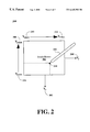
- FIG. 2 is a graphic representation of a sensing mechanism system 200 of touch screen 102 for use in an electronic touch screen device (e.g., portable personal computer 120 of FIG. 1B) in accordance with one embodiment of the present invention.
- touch screen 102 functions by employing a mechanism (e.g., resistive films) which produces two separate output signals. These output signals are analog voltages which correspond to the- position of stylus 108 (or an operator's finger) when it touches touch screen display 102 .
- Output voltage V x 202 of touch screen display 102 corresponds to the X coordinates of touch screen display 102
- output voltage V y 204 corresponds to the Y coordinates of touch screen display 102 .
- the voltage of V x 202 ranges from a minimum voltage V xmin 210 to a maximum voltage V xmax 212 , which directly corresponds to the range of X coordinates that extend from the left edge of touch screen display 102 to its right edge.
- the voltage of V y 204 ranges from a minimum voltage V ymin 206 to a maximum voltage V ymax 208 , which directly corresponds to the range of Y coordinates that extend from the bottom edge of touch screen display 102 to its top edge.
- touch screen display 102 outputs a specific V x 202 and a specific V y 204 , which together correspond to the position of stylus 108 (or a finger) on touch screen display 102 (e.g., dot 214 ). It should be appreciated that there are several conventional technologies for implementing these coordinate voltages within touch screen display 102 .
- FIG. 3 is a block diagram of a touch screen system 300 in accordance with one embodiment of the present invention for activating or “waking up” an electronic touch screen device (e.g., personal digital assistant 104 of FIG. 1A) from its quiescent low power state.
- an electronic touch screen device e.g., personal digital assistant 104 of FIG. 1A
- stylus 108 or a user's finger
- V y 204 is coupled to an analog to digital converter circuit 304 , where it is converted to a digital output signal 308 .
- V x 202 is coupled to an analog to digital converter circuit 306 , where it is converted to a digital output signal 310 .
- Digital output signals 308 and 310 are used by an electronic touch screen device for pixel generation, processing procedures, and so forth.
- An electronic touch screen device (e.g., portable personal computer 120 of FIG. 1B) can enter its quiescent low power state numerous ways, as described above. For instance, an operator of an electronic touch screen device can push a button forcing it into its quiescent low power state or an internal timer located within the electronic touch screen device can automatically force it into its quiescent low power state after a specific amount of non-use time has elapsed.
- the present invention involves activating or “waking up” an electronic touch screen device from its quiescent low power state, and is not concerned with the manner in which the electronic touch screen device entered into its quiescent low power state.
- touch screen display 102 of FIG. 3 is suspended at the minimum voltage levels of V ymin 206 and V xmin 210 , while analog to digital converter circuits 304 and 306 are turned off.
- One of the inputs of a voltage comparator circuit 302 is coupled to receive V x 202 from touch screen display 102 .
- the other input of voltage comparator circuit 302 is coupled to receive a reference voltage signal V ref 314 , which is set at some specific minimum voltage level.
- Voltage comparator 302 compares the voltage of V x 202 with the voltage of V ref 314 . It should be appreciated that the present invention is well suited to an embodiment in which a voltage comparator is implemented with software.
- resume event signal 312 is an interrupt signal that is transmitted to the processor (not shown) of the electronic touch screen device.
- This embodiment in accordance with the present invention, enables an operator to touch stylus 108 (or their finger) to touch screen display 102 in order to activate or “wake up” the electronic touch screen device from its quiescent low power state.
- the resulting outcome of the present invention system activates an electronic touch screen device from its quiescent low power state without requiring the user to manipulate specific buttons.
- the present invention system activates an electronic touch screen device without requiring the user to have extensive knowledge of the operation requirements of the electronic touch screen device.
- V x 202 and V y 204 output by touch screen display 102 of FIG. 3, in accordance with the present invention, are not strictly limited to positive voltages.
- the present invention is equally well suited to employ negative voltages for V x 202 and V y 204 .
- the voltage of V ref 314 changes and voltage comparator circuit 302 is connected differently to enable it to detect the change in V x 202 resulting from the touching of touch screen 102 .
- voltage comparator circuit 302 detects when touch screen 102 has been touched when the voltage of V x 202 is less than the voltage of V ref 314 .
- V ref 314 of FIG. 3 may be provided to comparator circuit 302 by numerous different voltage sources.
- V ref 314 may be provided by a voltage source located within the electronic touch screen device, e.g., by an application specific integrated circuit (ASIC).
- ASIC application specific integrated circuit
- V ref 314 may be supplied via a voltage source which is external to the electronic touch screen device.
- V ref 314 may be provided by a digital to analog converter circuit which is programmable via a central processing unit (CPU) accessible register.
- CPU central processing unit
- the voltage of V ref 314 has the ability to be adjusted for varying wake up detection voltage levels for different screens and varying conditions. In order to exclude any spurious wake up events of the electronic touch screen device, V ref 314 should be set at a slightly higher voltage than the minimum voltage of V xmin 210 .
- voltage comparator circuit 302 of FIG. 3 is located within analog to digital converter circuit 306 .
- voltage comparator circuit 302 shares the power supply (not shown) of analog to digital converter circuit 306 .
- FIG. 4 is a block diagram of a touch screen system 400 in accordance with another embodiment of the present invention for waking up any type of electronic touch screen device (e.g., portable personal computer 120 of FIG. 1B) from its quiescent low power state.
- Touch screen system 400 is connected and operates in a similar manner as touch screen system 300 of FIG. 3, except that one of the inputs of voltage comparator circuit 302 is connected to a different voltage source.
- Voltage comparator circuit 302 of FIG. 4 is connected to receive V y 204 from touch screen display 102 .
- the other input of the voltage comparator circuit 302 is connected to receive V ref 314 , which is set at some specific minimum voltage that is slightly higher than the minimum voltage of V ymin 206 .
- Voltage comparator circuit 302 compares the voltage of V y 204 against the voltage of V ref 314 . If the voltage of V y 204 is greater than the voltage of V ref 314 , voltage comparator circuit 302 outputs a resume event signal 312 which causes an electronic touch screen device to wake up from its quiescent low power state and return to its normal operations. As described above, this embodiment, in accordance with the present invention, enables an operator to advantageously touch stylus 108 (or their finger) to touch screen 102 in order to activate an electronic touch screen device from its quiescent low power state.
- voltage comparator circuit 302 of FIG. 4 is located within analog to digital converter circuit 304 .
- voltage comparator circuit 302 shares the power supply (not shown) of analog to digital converter circuit 304 .
- FIG. 5 is a flowchart of a method 500 in accordance with one embodiment of the present invention for activating an electronic touch screen device (e.g., personal digital assistant 104 of FIG. 1 A) from its quiescent low power state.
- FIG. 5 shows process 500 which starts at step 502 .
- the electronic touch screen device enters its quiescent low power state.
- a voltage comparator circuit ascertains if the touch screen display of the electronic touch screen device has been touched by determining whether the voltage of the X coordinate voltage signal output by the touch screen display is greater than the voltage of a reference voltage signal. During step 506 , if the X coordinate voltage signal is not greater that the reference voltage signal, the voltage comparator circuit returns to the beginning of step 506 and the electronic touch screen device remains within its quiescent low power state. If the X coordinate voltage signal is greater than the reference voltage signal during step 506 , the voltage comparator circuit proceeds to step 508 .
- the voltage comparator circuit transmits a resume event signal to the processor of the electronic touch screen device.
- step 510 of FIG. 5 the processor of the electronic touch screen device receives the resume event signal causing the electronic touch screen device to return to its active mode of normal operation.
- the electronic touch screen device exits process 500 of FIG. 5 during step 512 .
- FIG. 6 is a flowchart of a method 600 in accordance with another embodiment of the present invention for activating an electronic touch screen device (e.g., portable personal computer 120 of FIG. 1B) from its quiescent low power state.
- FIG. 6 shows process 600 which is similar to process 500 of FIG. 5 in that steps 502 , 504 , 508 , 510 , and 512 of process 600 are the same steps as described within process 500 .
- a voltage comparator circuit ascertains if the touch screen display of the electronic touch screen device has been touched by determining whether the voltage of the Y coordinate voltage signal output by the touch screen display is greater than the voltage of a reference voltage signal. During step 602 , if the Y coordinate voltage signal is not greater that the reference voltage signal, the voltage comparator circuit returns to the beginning of step 602 and the electronic touch screen device remains within its quiescent low power state. If the Y coordinate voltage signal is greater than the reference voltage signal during step 602 , the voltage comparator circuit proceeds to step 508 .
- the wake up system of the present invention activates an electronic touch screen device from it quiescent low power state without requiring the user to manipulate specific buttons. Moreover, the present invention system activates an electronic touch screen device without requiring the user to have extensive knowledge of the operation requirements of the electronic touch screen device. In addition, the wake up system of the present invention does not require any type of clocking signal to operate, enabling analog to digital converter circuits 304 and 306 of FIGS. 3 and 4 which utilize a clocking signal to remain off when the electronic touch screen device is within its quiescent low power state. Furthermore, since the wake up system of the present invention has a very low power requirement during operation, it does not adversely affect the battery life or power consumption of the electronic touch screen device.
Landscapes
- Engineering & Computer Science (AREA)
- Theoretical Computer Science (AREA)
- General Engineering & Computer Science (AREA)
- Physics & Mathematics (AREA)
- General Physics & Mathematics (AREA)
- Human Computer Interaction (AREA)
- Position Input By Displaying (AREA)
- Power Sources (AREA)
Abstract
Description
Claims (24)
Priority Applications (1)
| Application Number | Priority Date | Filing Date | Title |
|---|---|---|---|
| US09/020,629 US6445383B1 (en) | 1998-02-09 | 1998-02-09 | System to detect a power management system resume event from a stylus and touch screen |
Applications Claiming Priority (1)
| Application Number | Priority Date | Filing Date | Title |
|---|---|---|---|
| US09/020,629 US6445383B1 (en) | 1998-02-09 | 1998-02-09 | System to detect a power management system resume event from a stylus and touch screen |
Publications (1)
| Publication Number | Publication Date |
|---|---|
| US6445383B1 true US6445383B1 (en) | 2002-09-03 |
Family
ID=21799706
Family Applications (1)
| Application Number | Title | Priority Date | Filing Date |
|---|---|---|---|
| US09/020,629 Expired - Lifetime US6445383B1 (en) | 1998-02-09 | 1998-02-09 | System to detect a power management system resume event from a stylus and touch screen |
Country Status (1)
| Country | Link |
|---|---|
| US (1) | US6445383B1 (en) |
Cited By (41)
| Publication number | Priority date | Publication date | Assignee | Title |
|---|---|---|---|---|
| US6611257B1 (en) | 2000-09-29 | 2003-08-26 | Rockwell Automation Technologies, Inc. | Automatic detection of touch plane type |
| US20030197744A1 (en) * | 2000-05-11 | 2003-10-23 | Irvine Nes Stewart | Zeroclick |
| US6753853B1 (en) | 2000-09-29 | 2004-06-22 | Rockwell Automation Technologies, Inc. | Low power dissipation touch plane interface circuit |
| US6765558B1 (en) | 2000-09-29 | 2004-07-20 | Rockwell Automation Technologies, Inc. | Multiple touch plane compatible interface circuit and method |
| US20040173978A1 (en) * | 2003-03-06 | 2004-09-09 | Christopher Bowen | PTFE membranes and gaskets made therefrom |
| US20050078093A1 (en) * | 2003-10-10 | 2005-04-14 | Peterson Richard A. | Wake-on-touch for vibration sensing touch input devices |
| US6885365B1 (en) * | 2000-06-13 | 2005-04-26 | Lg Electronics Inc. | Glass touch sensing circuit |
| US6980201B1 (en) * | 2000-09-29 | 2005-12-27 | Rockwell Automation Technologies, Inc. | Minimum move touch plane scanning method and device |
| US20060083114A1 (en) * | 2004-10-19 | 2006-04-20 | Leadingham William R | One-touch time tracking system |
| US20060138983A1 (en) * | 2004-12-23 | 2006-06-29 | Samsung Electronics Co., Ltd. | Display device and driving apparatus thereof |
| US20060279553A1 (en) * | 2005-06-10 | 2006-12-14 | Soss David A | Force-based input device |
| US20060284856A1 (en) * | 2005-06-10 | 2006-12-21 | Soss David A | Sensor signal conditioning in a force-based touch device |
| US20070288779A1 (en) * | 2006-05-16 | 2007-12-13 | Lg Electronics Inc. | Controlling operation of information processing device using movement data |
| US20080030482A1 (en) * | 2006-07-31 | 2008-02-07 | Elwell James K | Force-based input device having an elevated contacting surface |
| US20080170043A1 (en) * | 2005-06-10 | 2008-07-17 | Soss David A | Force-based input device |
| US20080289885A1 (en) * | 2007-05-22 | 2008-11-27 | Elwell James K | Force-Based Input Device Having a Dynamic User Interface |
| US20090141436A1 (en) * | 2007-11-30 | 2009-06-04 | Yoshimichi Matsuoka | Trim element for housing of computing device |
| EP2090960A1 (en) * | 2008-02-18 | 2009-08-19 | Legrand France | Method and device for tactile interfacing |
| US20090231288A1 (en) * | 2008-03-17 | 2009-09-17 | Inventec Corporation | Hand-held electronic device and combined input method thereof |
| US7698084B2 (en) | 2005-06-10 | 2010-04-13 | Qsi Corporation | Method for determining when a force sensor signal baseline in a force-based input device can be updated |
| US20110080155A1 (en) * | 2009-10-02 | 2011-04-07 | Research In Motion Limited | Method of switching power modes and a portable electronic device configured to perform the same |
| US20110264928A1 (en) * | 2000-07-17 | 2011-10-27 | Microsoft Corporation | Changing power mode based on sensors in a device |
| CN103166621A (en) * | 2011-12-14 | 2013-06-19 | 罗伯特·博世有限公司 | Circuit arrangement for switching on electronic device |
| US20130169571A1 (en) * | 2011-12-30 | 2013-07-04 | Bowei Gai | Systems and methods for mobile device pairing |
| EP2741170A1 (en) * | 2012-12-10 | 2014-06-11 | BlackBerry Limited | Active stylus force sensing mechanism for generating a wakeup interrupt to the stylus controller |
| US8804332B2 (en) * | 1999-02-04 | 2014-08-12 | Hewlett-Packard Development Company, L.P. | Handheld computer |
| KR20140120261A (en) * | 2013-04-02 | 2014-10-13 | 삼성전자주식회사 | Method of controlling touch screen and electronic device thereof |
| CN104102378A (en) * | 2013-04-02 | 2014-10-15 | 三星电子株式会社 | Method of controlling touch screen and electronic device thereof |
| US20150039924A1 (en) * | 2013-07-24 | 2015-02-05 | Vega Grieshaber Kg | Field device |
| EP2749997A4 (en) * | 2011-08-22 | 2015-03-25 | Nec Casio Mobile Comm Ltd | State control device, state control method and program |
| US9081569B2 (en) | 2012-12-10 | 2015-07-14 | Blackberry Limited | Active stylus force sensing mechanism for generating a wakeup interrupt to the controller |
| US9098133B2 (en) | 2011-12-30 | 2015-08-04 | Linkedin Corporation | Mobile device pairing |
| US9479553B2 (en) | 2003-03-06 | 2016-10-25 | Microsoft Technology Licensing, Llc | Systems and methods for receiving, storing, and rendering digital video, music, and pictures on a personal media player |
| US20170041480A1 (en) * | 2012-04-20 | 2017-02-09 | Sharp Kabushiki Kaisha | Electric apparatus |
| CN106569583A (en) * | 2016-11-04 | 2017-04-19 | 惠州Tcl移动通信有限公司 | Double-click awakening screen power supply control method and system based on mobile terminal |
| US9736291B2 (en) | 2011-12-30 | 2017-08-15 | Linkedin Corporation | Mobile device pairing |
| US10120556B2 (en) | 2012-12-07 | 2018-11-06 | Microsoft Technology Licensing, Llc | Slide to apply |
| CN109388431A (en) * | 2018-09-19 | 2019-02-26 | 深圳创维汽车智能有限公司 | Screen awakening method, device and the storage medium of onboard system |
| US10739875B2 (en) | 2015-01-04 | 2020-08-11 | Microsoft Technology Licensing, Llc | Active stylus communication with a digitizer |
| TWI731410B (en) * | 2019-07-12 | 2021-06-21 | 聯詠科技股份有限公司 | Method, apparatus and system of using an active pen to wake a computer device from a power-saving mode |
| WO2022186730A2 (en) | 2021-03-05 | 2022-09-09 | Lyubeznov Valery Konstantinovich | Method for obtaining an optical scanning signal (options) |
Citations (4)
| Publication number | Priority date | Publication date | Assignee | Title |
|---|---|---|---|---|
| US5451724A (en) * | 1992-08-05 | 1995-09-19 | Fujitsu Limited | Touch panel for detecting a coordinate of an arbitrary position where pressure is applied |
| US5590343A (en) * | 1988-12-09 | 1996-12-31 | Dallas Semiconductor Corporation | Touch-sensitive switching circuitry for power-up |
| US5790875A (en) * | 1994-10-07 | 1998-08-04 | Nokia Mobile Phones Limited | Method for lowering power consumption in a computing device |
| US5949408A (en) * | 1995-09-28 | 1999-09-07 | Hewlett-Packard Company | Dual orientation display handheld computer devices |
-
1998
- 1998-02-09 US US09/020,629 patent/US6445383B1/en not_active Expired - Lifetime
Patent Citations (4)
| Publication number | Priority date | Publication date | Assignee | Title |
|---|---|---|---|---|
| US5590343A (en) * | 1988-12-09 | 1996-12-31 | Dallas Semiconductor Corporation | Touch-sensitive switching circuitry for power-up |
| US5451724A (en) * | 1992-08-05 | 1995-09-19 | Fujitsu Limited | Touch panel for detecting a coordinate of an arbitrary position where pressure is applied |
| US5790875A (en) * | 1994-10-07 | 1998-08-04 | Nokia Mobile Phones Limited | Method for lowering power consumption in a computing device |
| US5949408A (en) * | 1995-09-28 | 1999-09-07 | Hewlett-Packard Company | Dual orientation display handheld computer devices |
Cited By (70)
| Publication number | Priority date | Publication date | Assignee | Title |
|---|---|---|---|---|
| US8804332B2 (en) * | 1999-02-04 | 2014-08-12 | Hewlett-Packard Development Company, L.P. | Handheld computer |
| US9367083B2 (en) | 1999-02-04 | 2016-06-14 | Hewlett-Packard Development Company, L.P. | Computing device housing |
| US20030197744A1 (en) * | 2000-05-11 | 2003-10-23 | Irvine Nes Stewart | Zeroclick |
| US7818691B2 (en) * | 2000-05-11 | 2010-10-19 | Nes Stewart Irvine | Zeroclick |
| US20140195969A1 (en) * | 2000-05-11 | 2014-07-10 | Nes Stewart Irvine | Zeroclick |
| US6885365B1 (en) * | 2000-06-13 | 2005-04-26 | Lg Electronics Inc. | Glass touch sensing circuit |
| US9189069B2 (en) | 2000-07-17 | 2015-11-17 | Microsoft Technology Licensing, Llc | Throwing gestures for mobile devices |
| US20110264928A1 (en) * | 2000-07-17 | 2011-10-27 | Microsoft Corporation | Changing power mode based on sensors in a device |
| US9134760B2 (en) * | 2000-07-17 | 2015-09-15 | Microsoft Technology Licensing, Llc | Changing power mode based on sensors in a device |
| US6611257B1 (en) | 2000-09-29 | 2003-08-26 | Rockwell Automation Technologies, Inc. | Automatic detection of touch plane type |
| US6980201B1 (en) * | 2000-09-29 | 2005-12-27 | Rockwell Automation Technologies, Inc. | Minimum move touch plane scanning method and device |
| US6753853B1 (en) | 2000-09-29 | 2004-06-22 | Rockwell Automation Technologies, Inc. | Low power dissipation touch plane interface circuit |
| US6765558B1 (en) | 2000-09-29 | 2004-07-20 | Rockwell Automation Technologies, Inc. | Multiple touch plane compatible interface circuit and method |
| US7551163B1 (en) | 2000-09-29 | 2009-06-23 | Rockwell Automation Technologies, Inc. | Minimum move touch plane scanning method and device |
| US20040196269A1 (en) * | 2000-09-29 | 2004-10-07 | Dotson Gary Dan | Low power dissipation touch plane interface circuit |
| US7327354B2 (en) | 2000-09-29 | 2008-02-05 | Rockwell Automation Technologies, Inc. | Low power dissipation touch plane interface circuit |
| US9479553B2 (en) | 2003-03-06 | 2016-10-25 | Microsoft Technology Licensing, Llc | Systems and methods for receiving, storing, and rendering digital video, music, and pictures on a personal media player |
| US20040173978A1 (en) * | 2003-03-06 | 2004-09-09 | Christopher Bowen | PTFE membranes and gaskets made therefrom |
| US10178141B2 (en) | 2003-03-06 | 2019-01-08 | Microsoft Technology Licensing, Llc | Systems and methods for receiving, storing, and rendering digital video, music, and pictures on a personal media player |
| US20050078093A1 (en) * | 2003-10-10 | 2005-04-14 | Peterson Richard A. | Wake-on-touch for vibration sensing touch input devices |
| US7176902B2 (en) * | 2003-10-10 | 2007-02-13 | 3M Innovative Properties Company | Wake-on-touch for vibration sensing touch input devices |
| US20060083114A1 (en) * | 2004-10-19 | 2006-04-20 | Leadingham William R | One-touch time tracking system |
| US7973777B2 (en) * | 2004-12-23 | 2011-07-05 | Samsung Electronics Co., Ltd. | Display device and driving apparatus including a photo sensing circuit and a pressure sensing circuit and method thereof |
| US20060138983A1 (en) * | 2004-12-23 | 2006-06-29 | Samsung Electronics Co., Ltd. | Display device and driving apparatus thereof |
| US20060284856A1 (en) * | 2005-06-10 | 2006-12-21 | Soss David A | Sensor signal conditioning in a force-based touch device |
| US20060279553A1 (en) * | 2005-06-10 | 2006-12-14 | Soss David A | Force-based input device |
| US20080170043A1 (en) * | 2005-06-10 | 2008-07-17 | Soss David A | Force-based input device |
| US7698084B2 (en) | 2005-06-10 | 2010-04-13 | Qsi Corporation | Method for determining when a force sensor signal baseline in a force-based input device can be updated |
| US7903090B2 (en) | 2005-06-10 | 2011-03-08 | Qsi Corporation | Force-based input device |
| US20070288779A1 (en) * | 2006-05-16 | 2007-12-13 | Lg Electronics Inc. | Controlling operation of information processing device using movement data |
| US7885431B2 (en) | 2006-05-16 | 2011-02-08 | Lg Electronics Inc. | Controlling operation of information processing device using movement data |
| US20080030482A1 (en) * | 2006-07-31 | 2008-02-07 | Elwell James K | Force-based input device having an elevated contacting surface |
| US20080289885A1 (en) * | 2007-05-22 | 2008-11-27 | Elwell James K | Force-Based Input Device Having a Dynamic User Interface |
| US20080289887A1 (en) * | 2007-05-22 | 2008-11-27 | Qsi Corporation | System and method for reducing vibrational effects on a force-based touch panel |
| US20080289884A1 (en) * | 2007-05-22 | 2008-11-27 | Elwell James K | Touch-Based Input Device with Boundary Defining a Void |
| US20090141436A1 (en) * | 2007-11-30 | 2009-06-04 | Yoshimichi Matsuoka | Trim element for housing of computing device |
| FR2927710A1 (en) * | 2008-02-18 | 2009-08-21 | Legrand France | TOUCH INTERFACING METHOD AND DEVICE |
| US20090207147A1 (en) * | 2008-02-18 | 2009-08-20 | Alexandre Perrot | Touch-sensitive interface device and method |
| EP2090960A1 (en) * | 2008-02-18 | 2009-08-19 | Legrand France | Method and device for tactile interfacing |
| US20090231288A1 (en) * | 2008-03-17 | 2009-09-17 | Inventec Corporation | Hand-held electronic device and combined input method thereof |
| US8862913B2 (en) * | 2009-10-02 | 2014-10-14 | Blackberry Limited | Method of switching power modes and a portable electronic device configured to perform the same |
| US20110080155A1 (en) * | 2009-10-02 | 2011-04-07 | Research In Motion Limited | Method of switching power modes and a portable electronic device configured to perform the same |
| EP2749997A4 (en) * | 2011-08-22 | 2015-03-25 | Nec Casio Mobile Comm Ltd | State control device, state control method and program |
| CN103166621A (en) * | 2011-12-14 | 2013-06-19 | 罗伯特·博世有限公司 | Circuit arrangement for switching on electronic device |
| CN103166621B (en) * | 2011-12-14 | 2017-04-12 | 罗伯特·博世有限公司 | Circuit arrangement for switching on electronic device |
| US9098133B2 (en) | 2011-12-30 | 2015-08-04 | Linkedin Corporation | Mobile device pairing |
| US9137627B2 (en) * | 2011-12-30 | 2015-09-15 | Linkedin Corporation | Systems and methods for mobile device pairing |
| US20130169571A1 (en) * | 2011-12-30 | 2013-07-04 | Bowei Gai | Systems and methods for mobile device pairing |
| US9571956B2 (en) | 2011-12-30 | 2017-02-14 | Linkedin Corporation | Mobile device pairing |
| US9578481B2 (en) | 2011-12-30 | 2017-02-21 | Linkedin Corporation | Mobile device pairing |
| US9692869B2 (en) | 2011-12-30 | 2017-06-27 | Linkedin Corporation | Mobile device pairing |
| US9736291B2 (en) | 2011-12-30 | 2017-08-15 | Linkedin Corporation | Mobile device pairing |
| CN109981915A (en) * | 2012-04-20 | 2019-07-05 | 夏普株式会社 | Electrical equipment |
| US9769342B2 (en) | 2012-04-20 | 2017-09-19 | Sharp Kabushiki Kaisha | Electric apparatus |
| US20170041480A1 (en) * | 2012-04-20 | 2017-02-09 | Sharp Kabushiki Kaisha | Electric apparatus |
| US10120556B2 (en) | 2012-12-07 | 2018-11-06 | Microsoft Technology Licensing, Llc | Slide to apply |
| EP2741170A1 (en) * | 2012-12-10 | 2014-06-11 | BlackBerry Limited | Active stylus force sensing mechanism for generating a wakeup interrupt to the stylus controller |
| US9081569B2 (en) | 2012-12-10 | 2015-07-14 | Blackberry Limited | Active stylus force sensing mechanism for generating a wakeup interrupt to the controller |
| CN104102378A (en) * | 2013-04-02 | 2014-10-15 | 三星电子株式会社 | Method of controlling touch screen and electronic device thereof |
| US9310898B2 (en) | 2013-04-02 | 2016-04-12 | Samsung Electronics Co., Ltd. | Method of controlling touch screen with input pen and electronic device thereof |
| EP2787414A3 (en) * | 2013-04-02 | 2014-11-05 | Samsung Electronics Co., Ltd. | Method of controlling touch screen and electronic device thereof |
| CN104102378B (en) * | 2013-04-02 | 2019-03-12 | 三星电子株式会社 | Touch screen control method and electronic device thereof |
| KR20140120261A (en) * | 2013-04-02 | 2014-10-13 | 삼성전자주식회사 | Method of controlling touch screen and electronic device thereof |
| US9904347B2 (en) * | 2013-07-24 | 2018-02-27 | Vega Grieshaber Kg | Field device |
| US20150039924A1 (en) * | 2013-07-24 | 2015-02-05 | Vega Grieshaber Kg | Field device |
| US10739875B2 (en) | 2015-01-04 | 2020-08-11 | Microsoft Technology Licensing, Llc | Active stylus communication with a digitizer |
| CN106569583A (en) * | 2016-11-04 | 2017-04-19 | 惠州Tcl移动通信有限公司 | Double-click awakening screen power supply control method and system based on mobile terminal |
| CN109388431A (en) * | 2018-09-19 | 2019-02-26 | 深圳创维汽车智能有限公司 | Screen awakening method, device and the storage medium of onboard system |
| TWI731410B (en) * | 2019-07-12 | 2021-06-21 | 聯詠科技股份有限公司 | Method, apparatus and system of using an active pen to wake a computer device from a power-saving mode |
| WO2022186730A2 (en) | 2021-03-05 | 2022-09-09 | Lyubeznov Valery Konstantinovich | Method for obtaining an optical scanning signal (options) |
Similar Documents
| Publication | Publication Date | Title |
|---|---|---|
| US6445383B1 (en) | System to detect a power management system resume event from a stylus and touch screen | |
| US5487054A (en) | Method and apparatus for setting a clock in a computer system | |
| US7626582B1 (en) | Method and apparatus for automatic power-up and power-down of an electronic device | |
| US5884085A (en) | Portable computer having dedicated register group and peripheral controller bus between system bus and peripheral controller | |
| US6058485A (en) | Method and apparatus for managing power consumption of a digitizing panel | |
| US9189069B2 (en) | Throwing gestures for mobile devices | |
| US6243819B1 (en) | Lid switch in portable computers and the power management system using the same | |
| US5949408A (en) | Dual orientation display handheld computer devices | |
| US8120625B2 (en) | Method and apparatus using multiple sensors in a device with a display | |
| US10969857B2 (en) | Touch sensor mode transitioning | |
| US20090289908A1 (en) | Touch detecting device capable of saving electricity | |
| US20070057068A1 (en) | Portable electronic device and method for automatically switching power modes | |
| JPH0926832A (en) | Information processing apparatus and processing method | |
| US20100265209A1 (en) | Power reduction for touch screens | |
| JPH0784686A (en) | Portable pen input computer device | |
| US6772366B2 (en) | Method and apparatus for detecting AC removal | |
| EP3547089B1 (en) | Display device and the display method | |
| US6523122B1 (en) | Computer system for displaying system state information including advanced configuration and power interface states on a second display | |
| US12504807B1 (en) | Power regulation in an active display system | |
| EP1265126B1 (en) | Portable computer having dedicated register group and peripheral controller bus between system bus and peripheral controller | |
| CN101751205A (en) | Power management method for electronic device and related device | |
| CN111868681A (en) | Displaying ink rendering during system sleep | |
| JP3634402B2 (en) | Information processing method and apparatus | |
| US20050114775A1 (en) | User assisting program product, method, and information processing apparatus | |
| JPH06332571A (en) | Information processor |
Legal Events
| Date | Code | Title | Description |
|---|---|---|---|
| AS | Assignment |
Owner name: VLSI TECHNOLOGY, INC., CALIFORNIA Free format text: ASSIGNMENT OF ASSIGNORS INTEREST;ASSIGNORS:CHAMBERS, PETER;WENHUNT, OMER LEM, JR.;REEL/FRAME:008979/0820 Effective date: 19980206 |
|
| AS | Assignment |
Owner name: KONINKLIJKE PHILIPS ELECTRONICS N.V., NETHERLANDS Free format text: ASSIGNMENT OF ASSIGNORS INTEREST;ASSIGNOR:PHILIPS SEMICONDUCTORS, INC.;REEL/FRAME:013119/0425 Effective date: 20020715 |
|
| STCF | Information on status: patent grant |
Free format text: PATENTED CASE |
|
| FPAY | Fee payment |
Year of fee payment: 4 |
|
| AS | Assignment |
Owner name: NXP B.V., NETHERLANDS Free format text: ASSIGNMENT OF ASSIGNORS INTEREST;ASSIGNOR:KONINKLIJKE PHILIPS ELECTRONICS N.V.;REEL/FRAME:018635/0787 Effective date: 20061117 |
|
| FEPP | Fee payment procedure |
Free format text: PAYOR NUMBER ASSIGNED (ORIGINAL EVENT CODE: ASPN); ENTITY STATUS OF PATENT OWNER: LARGE ENTITY Free format text: PAYER NUMBER DE-ASSIGNED (ORIGINAL EVENT CODE: RMPN); ENTITY STATUS OF PATENT OWNER: LARGE ENTITY |
|
| FPAY | Fee payment |
Year of fee payment: 8 |
|
| AS | Assignment |
Owner name: PHILIPS SEMICONDUCTORS VLSI INC., NEW YORK Free format text: CHANGE OF NAME;ASSIGNOR:VLSI TECHNOLOGY, INC.;REEL/FRAME:030894/0204 Effective date: 19990702 Owner name: PHILIPS SEMICONDUCTORS INC., NEW YORK Free format text: CHANGE OF NAME;ASSIGNOR:PHILIPS SEMICONDUCTORS VLSI INC.;REEL/FRAME:030913/0312 Effective date: 19991220 |
|
| FPAY | Fee payment |
Year of fee payment: 12 |
|
| AS | Assignment |
Owner name: ST WIRELESS SA, SWITZERLAND Free format text: ASSIGNMENT OF ASSIGNORS INTEREST;ASSIGNOR:NXP B.V.;REEL/FRAME:037624/0831 Effective date: 20080728 |
|
| AS | Assignment |
Owner name: ST-ERICSSON SA, SWITZERLAND Free format text: CHANGE OF NAME;ASSIGNOR:ST WIRELESS SA;REEL/FRAME:037683/0128 Effective date: 20080714 Owner name: ST-ERICSSON SA, EN LIQUIDATION, SWITZERLAND Free format text: STATUS CHANGE-ENTITY IN LIQUIDATION;ASSIGNOR:ST-ERICSSON SA;REEL/FRAME:037739/0493 Effective date: 20150223 |