US6439126B1 - Enhanced kinetic energy projectile - Google Patents
Enhanced kinetic energy projectile Download PDFInfo
- Publication number
- US6439126B1 US6439126B1 US09/907,885 US90788501A US6439126B1 US 6439126 B1 US6439126 B1 US 6439126B1 US 90788501 A US90788501 A US 90788501A US 6439126 B1 US6439126 B1 US 6439126B1
- Authority
- US
- United States
- Prior art keywords
- projectile
- rounded end
- radius
- kinetic energy
- lead
- Prior art date
- Legal status (The legal status is an assumption and is not a legal conclusion. Google has not performed a legal analysis and makes no representation as to the accuracy of the status listed.)
- Expired - Fee Related
Links
- 229910000831 Steel Inorganic materials 0.000 claims abstract description 10
- 239000010959 steel Substances 0.000 claims abstract description 10
- 230000035515 penetration Effects 0.000 claims abstract description 7
- 239000000463 material Substances 0.000 abstract description 10
- 239000008188 pellet Substances 0.000 abstract description 8
- 231100000252 nontoxic Toxicity 0.000 description 3
- 230000003000 nontoxic effect Effects 0.000 description 3
- NCGICGYLBXGBGN-UHFFFAOYSA-N 3-morpholin-4-yl-1-oxa-3-azonia-2-azanidacyclopent-3-en-5-imine;hydrochloride Chemical compound Cl.[N-]1OC(=N)C=[N+]1N1CCOCC1 NCGICGYLBXGBGN-UHFFFAOYSA-N 0.000 description 2
- 230000005484 gravity Effects 0.000 description 2
- 238000004519 manufacturing process Methods 0.000 description 2
- WFKWXMTUELFFGS-UHFFFAOYSA-N tungsten Chemical compound [W] WFKWXMTUELFFGS-UHFFFAOYSA-N 0.000 description 2
- 229910052721 tungsten Inorganic materials 0.000 description 2
- 239000010937 tungsten Substances 0.000 description 2
- 241000272517 Anseriformes Species 0.000 description 1
- 229910052770 Uranium Inorganic materials 0.000 description 1
- 239000000956 alloy Substances 0.000 description 1
- 229910045601 alloy Inorganic materials 0.000 description 1
- 229910052797 bismuth Inorganic materials 0.000 description 1
- JCXGWMGPZLAOME-UHFFFAOYSA-N bismuth atom Chemical compound [Bi] JCXGWMGPZLAOME-UHFFFAOYSA-N 0.000 description 1
- 150000001875 compounds Chemical class 0.000 description 1
- 238000010276 construction Methods 0.000 description 1
- 230000000694 effects Effects 0.000 description 1
- 238000010304 firing Methods 0.000 description 1
- 230000010354 integration Effects 0.000 description 1
- 238000000034 method Methods 0.000 description 1
- 238000012986 modification Methods 0.000 description 1
- 230000004048 modification Effects 0.000 description 1
- 231100000956 nontoxicity Toxicity 0.000 description 1
- DNYWZCXLKNTFFI-UHFFFAOYSA-N uranium Chemical compound [U][U][U][U][U][U][U][U][U][U][U][U][U][U][U][U][U][U][U][U][U][U][U][U][U][U][U][U][U][U][U][U][U][U][U][U][U][U][U][U][U][U][U][U][U][U][U][U][U][U][U][U][U][U][U][U][U][U][U][U][U][U][U][U][U][U][U][U][U][U][U][U][U][U][U][U][U][U][U][U][U][U][U][U][U][U][U][U][U][U][U][U][U][U][U][U][U][U][U][U][U][U][U][U][U][U][U][U][U][U][U][U][U][U] DNYWZCXLKNTFFI-UHFFFAOYSA-N 0.000 description 1
Images


Classifications
-
- F—MECHANICAL ENGINEERING; LIGHTING; HEATING; WEAPONS; BLASTING
- F42—AMMUNITION; BLASTING
- F42B—EXPLOSIVE CHARGES, e.g. FOR BLASTING, FIREWORKS, AMMUNITION
- F42B7/00—Shotgun ammunition
- F42B7/02—Cartridges, i.e. cases with propellant charge and missile
- F42B7/04—Cartridges, i.e. cases with propellant charge and missile of pellet type
- F42B7/046—Pellets or shot therefor
Definitions
- Contemporary forces using shoulder-fired weapons utilize multiple projectile munitions, typically spherical pellets.
- the term for such weapons firing multiple projectiles is a “shotgun” and the cartridges “shotgun shells.”
- shotguns for military applications are the ability to hit rapidly moving personnel and vehicles at close ranges, ability to engage large numbers of closely spaced personnel and the ability to engage them in limited visibility scenarios (e.g. thick foliage).
- All commercially available shotgun shells use spherical projectiles because they are easy to manufacture and to load into the cartridges.
- spherical pellets there are two major problems with spherical pellets: 1. they scatter randomly after they leave the muzzle of the gun, thereby increasing the likelihood of causing casualties among non-combatants, and 2. they rapidly slow down in flight due to aerodynamic inefficiency.
- the instant invention is a steel projectile assuming the general shape of a teardrop. This elongated exterior geometry enables the steel projectile to compensate for the lower density of the material as compared to lead and achieve penetration into the target that is comparable to spherical lead pellets while suffering less scatter and aerodynamic drag (i.e. being more directional).
- FIG. 1 illustrates the general shape of enhanced kinetic energy projectile.
- FIG. 2 is a detailed illustration of the structure of the projectile.
- FIG. 3 shows Region I for volume calculation.
- FIG. 4 shows Region II for volume calculation.
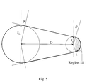
- FIG. 5 shows Region III for volume calculation.
- FIG. 6 depicts the enhanced kinetic energy projectile with advantageously located center of gravity.
- FIG. 1 depicts the general teardrop shape of the enhanced kinetic energy projectile 100 , the smaller-radius area being the front end so as to minimize the pressure drag during the flight of the projectile.
- projectile 100 can be deemed to be made of three segments that are integrated together. At the front end is small sphere 200 , large sphere 202 at the rear end and tapered segment 204 connecting the two spheres. There are three parameters that need to be chosen carefully when fabricating the projectile, taking into consideration factors such as the distance to be traveled by the projectile and the desired velocity of the travel. These parameters are r L , r s and D, denoting, respectively, the radius of large sphere 202 , the radius of small sphere 200 and the distance between the centers of the spheres 200 and 202 . To be effective in maintaining the desired flight path and achieving penetration at the intended target, D should be equal to or greater than the sum of r L and r s .
- V II ⁇ ⁇ [ 1 3 ⁇ m 2 ⁇ ⁇ ( D + b ) 3 - a 3 ⁇ + mr 3 ⁇ ⁇ ( D + b ) 2 - a 2 ⁇ + r 3 2 ⁇ ( D + b - a ) ] ( 2 )
- the total volume of the projectile is simply the sum of V I , V II , and V III and the weight is the product of the total volume and the density of the given material.
- the teardrop shape of the projectile causes it to suffer less aerodynamic drag than a spherical projectile of equal volume while pressure drag and skin friction drag can be minimized by controlling r s and D, respectively (i.e. each type of drag increases as the corresponding dimension increases).
- FIG. 6 Stability of the projectile during flight can be enhanced by locating the center of gravity as close to the front end as possible.
- the projectile shown in this figure has the same external configuration as the projectile shown in FIG. 1 but larger, rear rounded end 202 and most of tapered segment 204 are hollow, being filled only with air, while smaller, front rounded end 200 and a fraction of the tapered segment are filled with lead.
- the rear rounded end and the front rounded end encompass a longer and a shorter radii, respectively.
- This concentration of heavy material at the nose of the projectile imparts greater in-flight stability to the projectile.
- projectile 100 may comprise steel shell 601 of a pre-selected thickness and a lead insert in the front section of the projectile while the remainder of the interior space of the projectile is filled with air.
- the steel shell meets any non-toxicity requirement.
Landscapes
- Engineering & Computer Science (AREA)
- General Engineering & Computer Science (AREA)
- Aiming, Guidance, Guns With A Light Source, Armor, Camouflage, And Targets (AREA)
Abstract
A steel projectile assuming the general shape of a teardrop compensates for the lower density of the material as compared to lead and still achieves penetration into the target that is comparable to spherical lead pellets. Additional benefit of the elongated exterior geometry of the projectile is less scatter and less aerodynamic drag during flight.
Description
The invention described herein may be manufactured, used and licensed by or for the Government for governmental purposes without the payment to us of any royalties thereon.
Contemporary forces using shoulder-fired weapons utilize multiple projectile munitions, typically spherical pellets. The term for such weapons firing multiple projectiles is a “shotgun” and the cartridges “shotgun shells.”
The benefits of shotguns for military applications are the ability to hit rapidly moving personnel and vehicles at close ranges, ability to engage large numbers of closely spaced personnel and the ability to engage them in limited visibility scenarios (e.g. thick foliage). All commercially available shotgun shells use spherical projectiles because they are easy to manufacture and to load into the cartridges. However, there are two major problems with spherical pellets: 1. they scatter randomly after they leave the muzzle of the gun, thereby increasing the likelihood of causing casualties among non-combatants, and 2. they rapidly slow down in flight due to aerodynamic inefficiency.
The classic approach to extending the range of shotgun pellets is to use denser pellet material. Traditionally, shotgun pellets have been made of lead, which is one of the heavier elements yet easy to manipulate during manufacture. Using alloys containing tungsten, uranium, etc. has been considered but has not met wide-spread use due to cost, marginal performance improvement and material hardness which renders the material difficult to work with. One notable application where materials other than lead have been used in pellet construction is in non-toxic shots. Non-toxic shots are required in the United States for certain activities such as hunting waterfowl. Unfortunately, though, these non-toxic shot materials are high in cost. Commercial shells made of compounds of bismuth and tungsten are typically three to four times more expensive than corresponding lead shells. Currently available steel shells cost approximately 100% more than corresponding lead shells, while lagging far behind the lead shells in performance. The reason for the lackluster performance is that steel is only 71% as dense as lead, which means that a steel projectile of the same size as a lead projectile has less kinetic energy and corresponding less penetration than the lead projectile.
The instant invention is a steel projectile assuming the general shape of a teardrop. This elongated exterior geometry enables the steel projectile to compensate for the lower density of the material as compared to lead and achieve penetration into the target that is comparable to spherical lead pellets while suffering less scatter and aerodynamic drag (i.e. being more directional).
FIG. 1 illustrates the general shape of enhanced kinetic energy projectile.
FIG. 2 is a detailed illustration of the structure of the projectile.
FIG. 3 shows Region I for volume calculation.
FIG. 4 shows Region II for volume calculation.
FIG. 5 shows Region III for volume calculation.
FIG. 6 depicts the enhanced kinetic energy projectile with advantageously located center of gravity.
Referring now to the drawing wherein like numbers represent like parts in each of the several figures, FIG. 1 depicts the general teardrop shape of the enhanced kinetic energy projectile 100, the smaller-radius area being the front end so as to minimize the pressure drag during the flight of the projectile.
As detailed in FIG. 2, projectile 100 can be deemed to be made of three segments that are integrated together. At the front end is small sphere 200, large sphere 202 at the rear end and tapered segment 204 connecting the two spheres. There are three parameters that need to be chosen carefully when fabricating the projectile, taking into consideration factors such as the distance to be traveled by the projectile and the desired velocity of the travel. These parameters are rL, rs and D, denoting, respectively, the radius of large sphere 202, the radius of small sphere 200 and the distance between the centers of the spheres 200 and 202. To be effective in maintaining the desired flight path and achieving penetration at the intended target, D should be equal to or greater than the sum of rL and rs. Another factor that impacts the effectiveness of the penetration and the ability to fly straight at the target is the weight of the projectile. Generally, given the same volume, the heavier projectile achieves straighter flight path and deeper penetration than the lighter projectile. The weight being simply the product of the total volume and the density of the material, it is then important to calculate and control the desired volume. It is instructive now to review the method of calculating the volume of the projectile as it is depicted in FIG. 1. For this purpose, the projectile is divided into three regions, as depicted by speckled areas in FIGS. 3, 4 and 5. The volume of region I is given by 
where a=rL sin(θ) and θ=sin−1 
The volume of Region II, using the circular cylindrical coordinate system to facilitate integration, is given by 
where 
m=−tan(θ) and b=r, sin (θ).
Finally, the volume of Region III is given by 
The total volume of the projectile is simply the sum of VI, VII, and VIII and the weight is the product of the total volume and the density of the given material.
The teardrop shape of the projectile causes it to suffer less aerodynamic drag than a spherical projectile of equal volume while pressure drag and skin friction drag can be minimized by controlling rs and D, respectively (i.e. each type of drag increases as the corresponding dimension increases).
Stability of the projectile during flight can be enhanced by locating the center of gravity as close to the front end as possible. One way to accomplish this is illustrated in FIG. 6. The projectile shown in this figure has the same external configuration as the projectile shown in FIG. 1 but larger, rear rounded end 202 and most of tapered segment 204 are hollow, being filled only with air, while smaller, front rounded end 200 and a fraction of the tapered segment are filled with lead. The rear rounded end and the front rounded end encompass a longer and a shorter radii, respectively. This concentration of heavy material at the nose of the projectile imparts greater in-flight stability to the projectile. As illustrated in FIG. 6, projectile 100 may comprise steel shell 601 of a pre-selected thickness and a lead insert in the front section of the projectile while the remainder of the interior space of the projectile is filled with air. The steel shell meets any non-toxicity requirement.
Although a particular embodiment and form of this invention has been illustrated, it is apparent that various modifications and embodiments of the invention may be made by those skilled in the art without departing from the scope and spirit of the foregoing disclosure. Accordingly, the scope of the invention should be limited only by the claims appended hereto.
Claims (2)
1. An enhanced kinetic energy projectile shaped to maximize effective penetration while minimizing aerodynamic drag during flight, said projectile comprising: a steel shell having a pre-selected thickness and a hollow, air-filled interior, said steel shell assuming a teardrop shape, said shape comprising a front rounded end encompassing a first radius; a rear rounded end encompassing a second radius, said first radius being shorter than said second radius; a tapered section between said rounded ends; and a lead insert, said insert being positioned inside said shell adjacent to said front rounded end to impart greater in-flight stability to said projectile.
2. An enhanced kinetic energy projectile as set forth in claim 1 , wherein said lead insert fills the interior of said front rounded end and a portion of said tapered section immediately adjacent to said front rounded end.
Priority Applications (1)
| Application Number | Priority Date | Filing Date | Title |
|---|---|---|---|
| US09/907,885 US6439126B1 (en) | 2001-07-16 | 2001-07-16 | Enhanced kinetic energy projectile |
Applications Claiming Priority (1)
| Application Number | Priority Date | Filing Date | Title |
|---|---|---|---|
| US09/907,885 US6439126B1 (en) | 2001-07-16 | 2001-07-16 | Enhanced kinetic energy projectile |
Publications (1)
| Publication Number | Publication Date |
|---|---|
| US6439126B1 true US6439126B1 (en) | 2002-08-27 |
Family
ID=25424806
Family Applications (1)
| Application Number | Title | Priority Date | Filing Date |
|---|---|---|---|
| US09/907,885 Expired - Fee Related US6439126B1 (en) | 2001-07-16 | 2001-07-16 | Enhanced kinetic energy projectile |
Country Status (1)
| Country | Link |
|---|---|
| US (1) | US6439126B1 (en) |
Cited By (3)
| Publication number | Priority date | Publication date | Assignee | Title |
|---|---|---|---|---|
| US20040007149A1 (en) * | 2002-07-12 | 2004-01-15 | Arthur Vanmoor | Hydrodynamically and aerodynamically optimized leading and trailing edge configurations |
| US7096791B2 (en) * | 2002-07-12 | 2006-08-29 | Arthur Vanmoor | Projectile with improved dynamic shape |
| US8567298B2 (en) | 2011-02-16 | 2013-10-29 | Ervin Industries, Inc. | Cost-effective high-volume method to produce metal cubes with rounded edges |
Citations (8)
| Publication number | Priority date | Publication date | Assignee | Title |
|---|---|---|---|---|
| US2306140A (en) * | 1940-09-27 | 1942-12-22 | George E Dieckman | Projectile and bullet |
| US3400660A (en) * | 1965-10-20 | 1968-09-10 | Richard L. Malter | Ammunition projectile |
| US4167904A (en) * | 1977-09-15 | 1979-09-18 | Ferri Bernard L | Shot compressor devices and method therefor |
| US4718348A (en) * | 1986-05-16 | 1988-01-12 | Ferrigno John E | Grooved projectiles |
| US4996924A (en) * | 1987-08-11 | 1991-03-05 | Mcclain Harry T | Aerodynamic air foil surfaces for in-flight control for projectiles |
| US5016536A (en) * | 1988-04-11 | 1991-05-21 | Rainier International, Inc. | Non-lethal practice round for automatic and semiautomatic firearms |
| DE4135466A1 (en) * | 1991-10-28 | 1993-04-29 | Georg Diamantidis | Hunting shotgun cartridges and rifle bullets - have streamlined tear-drop-shaped shot and bullets |
| US5877437A (en) | 1992-04-29 | 1999-03-02 | Oltrogge; Victor C. | High density projectile |
-
2001
- 2001-07-16 US US09/907,885 patent/US6439126B1/en not_active Expired - Fee Related
Patent Citations (8)
| Publication number | Priority date | Publication date | Assignee | Title |
|---|---|---|---|---|
| US2306140A (en) * | 1940-09-27 | 1942-12-22 | George E Dieckman | Projectile and bullet |
| US3400660A (en) * | 1965-10-20 | 1968-09-10 | Richard L. Malter | Ammunition projectile |
| US4167904A (en) * | 1977-09-15 | 1979-09-18 | Ferri Bernard L | Shot compressor devices and method therefor |
| US4718348A (en) * | 1986-05-16 | 1988-01-12 | Ferrigno John E | Grooved projectiles |
| US4996924A (en) * | 1987-08-11 | 1991-03-05 | Mcclain Harry T | Aerodynamic air foil surfaces for in-flight control for projectiles |
| US5016536A (en) * | 1988-04-11 | 1991-05-21 | Rainier International, Inc. | Non-lethal practice round for automatic and semiautomatic firearms |
| DE4135466A1 (en) * | 1991-10-28 | 1993-04-29 | Georg Diamantidis | Hunting shotgun cartridges and rifle bullets - have streamlined tear-drop-shaped shot and bullets |
| US5877437A (en) | 1992-04-29 | 1999-03-02 | Oltrogge; Victor C. | High density projectile |
Cited By (5)
| Publication number | Priority date | Publication date | Assignee | Title |
|---|---|---|---|---|
| US20040007149A1 (en) * | 2002-07-12 | 2004-01-15 | Arthur Vanmoor | Hydrodynamically and aerodynamically optimized leading and trailing edge configurations |
| US7017508B2 (en) * | 2002-07-12 | 2006-03-28 | Arthur Vanmoor | Hydrodynamically and aerodynamically optimized leading and trailing edge configurations |
| US7096791B2 (en) * | 2002-07-12 | 2006-08-29 | Arthur Vanmoor | Projectile with improved dynamic shape |
| US8567298B2 (en) | 2011-02-16 | 2013-10-29 | Ervin Industries, Inc. | Cost-effective high-volume method to produce metal cubes with rounded edges |
| US8726778B2 (en) | 2011-02-16 | 2014-05-20 | Ervin Industries, Inc. | Cost-effective high-volume method to produce metal cubes with rounded edges |
Similar Documents
| Publication | Publication Date | Title |
|---|---|---|
| US11118883B2 (en) | Projectile with enhanced ballistic efficiency | |
| US4913054A (en) | Projectile delivery apparatus | |
| US11549789B2 (en) | Optimized subsonic projectiles | |
| CA1278952C (en) | Ammunition round | |
| US8082851B2 (en) | Cavitating core | |
| US20180120069A1 (en) | Projectile | |
| EP2613119B1 (en) | Bullet including an air-guiding recess | |
| US4742774A (en) | Small arms ammunition | |
| US4212244A (en) | Small arms ammunition | |
| ES2930873T3 (en) | Improved fragmentation projectile and method for its manufacture | |
| US12163769B2 (en) | Cavitating projectile of firearm ammunition | |
| RU2150077C1 (en) | Armor-piercing bullet | |
| US20180135950A1 (en) | Frangible Bullet Tip | |
| US6439126B1 (en) | Enhanced kinetic energy projectile | |
| US4961384A (en) | Hypervelocity penetrator for an electromagnetic accelerator | |
| US5092246A (en) | Small arms ammunition | |
| US8640625B1 (en) | Kinetic energy training projectile | |
| US9322622B2 (en) | Shotshell with combination slug and shot load | |
| US11415398B2 (en) | Gas favoring boattail projectile | |
| JP7178419B2 (en) | Apparatus and method for providing a horizontal dispersion pattern | |
| Braun | Aerodynamic data for small arms projectiles | |
| WO1981001046A1 (en) | Small arms ammunition | |
| USH700H (en) | Probe nose training cartridge | |
| RU74197U1 (en) | SINGLE COMPONENT BULLET | |
| RU2809501C1 (en) | Small arms cartridge with increased penetration |
Legal Events
| Date | Code | Title | Description |
|---|---|---|---|
| AS | Assignment |
Owner name: UNITED STATES OF AMERICA, AS REPRESENTED BY THE SE Free format text: ASSIGNMENT OF ASSIGNORS INTEREST;ASSIGNORS:KENNEDY, KEVIN D.;SMITH, BRIAN J.;REEL/FRAME:012810/0316 Effective date: 20010705 |
|
| FPAY | Fee payment |
Year of fee payment: 4 |
|
| REMI | Maintenance fee reminder mailed | ||
| LAPS | Lapse for failure to pay maintenance fees | ||
| STCH | Information on status: patent discontinuation |
Free format text: PATENT EXPIRED DUE TO NONPAYMENT OF MAINTENANCE FEES UNDER 37 CFR 1.362 |
|
| FP | Lapsed due to failure to pay maintenance fee |
Effective date: 20100827 |