US6432275B1 - Headbox of a paper/board machine by whose means the basis weight of the web can be regulated - Google Patents
Headbox of a paper/board machine by whose means the basis weight of the web can be regulated Download PDFInfo
- Publication number
- US6432275B1 US6432275B1 US09/622,336 US62233600A US6432275B1 US 6432275 B1 US6432275 B1 US 6432275B1 US 62233600 A US62233600 A US 62233600A US 6432275 B1 US6432275 B1 US 6432275B1
- Authority
- US
- United States
- Prior art keywords
- flow
- headbox
- stock
- thickening
- tube
- Prior art date
- Legal status (The legal status is an assumption and is not a legal conclusion. Google has not performed a legal analysis and makes no representation as to the accuracy of the status listed.)
- Expired - Fee Related
Links
Images


Classifications
-
- D—TEXTILES; PAPER
- D21—PAPER-MAKING; PRODUCTION OF CELLULOSE
- D21F—PAPER-MAKING MACHINES; METHODS OF PRODUCING PAPER THEREON
- D21F1/00—Wet end of machines for making continuous webs of paper
- D21F1/02—Head boxes of Fourdrinier machines
-
- D—TEXTILES; PAPER
- D21—PAPER-MAKING; PRODUCTION OF CELLULOSE
- D21F—PAPER-MAKING MACHINES; METHODS OF PRODUCING PAPER THEREON
- D21F1/00—Wet end of machines for making continuous webs of paper
- D21F1/06—Regulating pulp flow
-
- D—TEXTILES; PAPER
- D21—PAPER-MAKING; PRODUCTION OF CELLULOSE
- D21F—PAPER-MAKING MACHINES; METHODS OF PRODUCING PAPER THEREON
- D21F1/00—Wet end of machines for making continuous webs of paper
- D21F1/08—Regulating consistency
Definitions
- the invention concerns a headbox for a paper/board machine by whose means the basis weight of the web can be regulated.
- a dilution fluid favourably dilution water
- the dilution water is passed to the desired area of width into connection with the stock flow passed from the stock inlet header.
- the dilution water is favourably passed from an inlet header of its own through separate flow ducts, which flow ducts comprise a valve that regulates the flow.
- the dilution fluid can be passed to the desired areas of width of the web and as the desired quantities.
- a method of an entirely novel type is suggested for regulation of the basis weight of a web, which method is based on removal of a flow component whose concentration differs from the average stock concentration out of the stock flow.
- a separate thickening element which comprises a chamber space, into which chamber an inlet tube is opened and out of which chamber an outlet duct departs.
- the main flow is passed further, and the proportion whose concentration differs from the average concentration of the stock suspension and which contains a smaller amount of fibers and whose basis weight is lower than the average basis weight of the stock is passed first out of the side walls of the tube that passes into the chamber space of the thickening element and after that away from the side face of the chamber space through a duct which opens at said face.
- the flow tends to be differentiated so that the proportion with a higher concentration of solid matter flows in the middle of the tube, and the proportion with a lower concentration of fibers flows in the lateral areas of the tube.
- Said lateral proportion is passed further into the chamber space of the thickening element and away from the chamber space through the duct placed at the side wall of the chamber space.
- the total flow is denoted with L.
- the flow L consists of a flow proportion L 2 flowing in the middle of the inlet tube and passed forwards, and of a flow proportion L 1 flowing along the faces of the tube and to be removed from the headbox.
- the middle flow L 2 contains a higher concentration of solid matter than the flow proportion L 1 to be removed does.
- the flow L 2 is passed forwards in the headbox, and the flow L 1 is removed through the thickening element.
- the central flow L 2 with a higher concentration of fibers is passed forwards, and the flow L 1 with a lower concentration of fibers, from the walls of the tube, is removed through the thickening element.
- the flow quantity (liters per minute) of the flow L is always invariable.
- the flow quantity of the flow proportion L 1 removed from the headbox can be regulated by means of the valves V 1 , V 2 , it is further possible to regulate the concentration of the central flow L 2 .
- the proportion L 1 to be removed must be compensated for by a corresponding increase in the flow introduced into the thickening element.
- the thickening element is fitted in the vicinity of the stock inlet header of the headbox.
- the flow proportion L 1 X 1 liters per minute
- Said compensation for the flow quantity (X 1 liters per minute) that has been passed away takes place, in an embodiment of the invention, so that a separate duct is passed from the stock inlet header to the outlet side of the thickening element.
- a compensation flow L 3 into connection with the flow L 2 .
- the sum flow L 3 +L 2 is always as desired and unchanged, i.e. invariable.
- flows are spoken of (e.g. sum flow and differential flow), what is meant is flow quantity per unit of time, for example liters per minute.
- the headbox in accordance with the invention for regulation of the basis weight of the web in a paper/board machine is characterized in what is stated in the patent claims.
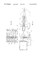
- FIG. 1 is an axonometric view of an equipment in accordance with the invention, being partly an illustration of principle.
- FIG. 2A is a sectional view of a thickening unit employed in the equipment in accordance with the invention.
- FIG. 2B shows a second embodiment of a thickening element in accordance with the invention.
- FIG. 2C shows an embodiment of a headbox connected with the thickening element shown in FIG. 2 B.
- FIG. 2D is a sectional view taken along the line II—II in FIG. 2 C.
- FIG. 3A shows an embodiment of the invention in which the thickening elements have been fitted right in the vicinity of the intermediate chamber of the stilling chamber G and in which construction the stilling chamber O is provided with an overflow.
- FIG. 3B shows a set of thickening elements in an area of width for use in the construction as shown in FIG. 3 A.
- FIG. 4A shows an embodiment of the invention in which the thickening elements have been arranged right in the vicinity of the stock inlet header at a suitable distance from the stock inlet header, in which connection both there is time for a concentration profile to be formed and the pressure in the stock inlet header equalizes the flows so that the flow L 1 that is removed from the thickening element is compensated for by an additional-flow quantity passed from the stock inlet header.
- FIG. 4B is a sectional view taken along the line I—I in FIG. 4 A.
- FIG. 1 shows a headbox construction 10 in accordance with the invention.
- the headbox 10 comprises a stock inlet header J 1 , which becomes narrower towards its end in the cross direction and from which header the stock is passed, in the embodiment shown in FIG. 1, through the tubes 11 a 1 , 11 a 2 . . . in the single-row tube bank 11 further to thickening elements 12 a 1 , 12 a 2 , 12 a 3 . . . .
- Each tube 11 a 1 , 11 a 2 . . . is connected with a thickening element 12 a 2 , 12 a 2 . . . .
- part of the stock flow is removed from the lateral areas of the stock flow into the ducts D 1 , D 2 . . . and further into a collecting header 13 as a flow proportion L 1 .
- a duct D 1 , D 2 . . . of its own passes to the collecting header 13 .
- Each duct D 1 , D 2 . . . is provided with a valve V 1 , V 2 . . . , by whose means it is possible to regulate the flow L 1 to be removed from the thickening element 12 a 1 , 12 a 2 . . . .
- the flow L 1 is taken in the thickening element 12 a 1 , 12 a 2 . . . from the lateral areas of the chamber space 18 (in FIG. 2 A). Said removed proportion or component of the flow differs, in respect of its consistency, from the flow L 2 that is passed further, which flow L 2 is passed further expressly from the middle of the thickening element 12 a 1 , 12 a 2 . . . .
- the tubes 14 a 1 , 14 a 2 , 14 a 3 . . . in the single-row tube bank pass into an intermediate chamber E, which is opened from the top into a stilling chamber G and from which intermediate chamber E the stock flow is passed into the tubes 15 a 1.1 , 15 a 1.2 in the turbulence generator 15 and further into the slice cone K and onto the forming wire H.
- an additional flow L 3 is passed into connection with the flow L 2 coming from the thickening elements 12 a 1 , 12 a 2 . . . .
- the additional flow L 3 compensates for the flow quantity L 1 that has been removed at each thickening element 12 a 1 , 12 a 2 . . . , so that the flow quantity L 2 +L 3 is always unchanged, i.e. invariable, after each thickening element 12 a 1 , 12 a 2 . . . .
- FIG. 2A is a sectional view of a thickening element 12 a 1 .
- the thickening element 12 a 1 comprises a chamber space 18 , to which a tube 11 a 1 of the tube bank 11 is connected from the inlet side.
- the tube 11 a 1 extends into the interior of the chamber space 18 similarly to a projection.
- Out of the chamber space 18 there is an exhaust duct 14 a 1 .
- the flow L 1 whose consistency differs from the consistency of the stock flow L 2 passing in the middle of the tube 11 a 1 , is transferred from the lateral areas 18 c of the thickening element 12 a 1 , 12 a 2 . . . out of the chamber space 18 as exhaust into the duct D 1 .
- the component L 2 of higher consistency taken from the middle of the thickening element 12 a 1 , 12 a 2 . . . is transferred further in the headbox and first into the tube 14 a 1 .
- FIG. 2B illustrates a second preferred embodiment of a thickening element 12 a 1 , 12 a 2 . . . .
- the thickening element 12 a 1 comprises a frame 18 a preferably a tubular frame, which confines a chamber space 18 in its interior.
- a tube 11 a 1 is passed, which tube comprises flow openings f 1 , f 2 , f 3 . . . , which open into the chamber space 18 a .
- FIG. 2B The embodiment of the invention shown in FIG. 2B is in the other respects similar to the embodiments shown in the preceding figures, the only difference being that the thickening element 12 a 1 comprises a perforated f 1 , f 2 . . . tube portion 11 a 1 , 11 a 2 . . . passing through the chamber space 18 a .
- a thickening element as shown in FIG. 1
- the headbox comprises a stock inlet header J 1 and from it, as is shown in the embodiment of FIG. 4A, flow tubes 11 a 1 , 11 a 2 passing into the intermediate chamber E and further from it, through the tubes 15 a 1.1 , 15 a 1.2 in the turbulence generator 15 , the flow is passed into the slice cone K and further onto the forming wire H 1 .
- FIG. 2C shows an embodiment related to the thickening element 12 a shown in FIG. 2 B.
- the thickening elements 12 a 1 , 12 a 2 . . . are connected with flow tubes 11 a 1 , 11 a 2 . . . which open into the intermediate chamber E. From the intermediate chamber, the flow passes into the turbulence generator 15 and from it further through the slice cone onto the forming wire H.
- FIG. 2D is a sectional view taken along the line II—II in FIG. 2 C.
- Thickening elements 12 a 1 , 12 a 2 . . . have been fitted in different positions of width of the headbox in view of regulation of the basis weight of the web across the web width as desired.
- FIG. 3A shows an embodiment of the invention in which the thickening elements 12 a 1 , 12 a 2 . . . have been fitted right in the vicinity of the intermediate chamber E, into which intermediate chamber E further a stilling chamber G is opened.
- the diameter of the tubes 11 a 1 , 11 a 2 . . . passing to the thickening elements 12 a 1 , 12 a 2 . . . is denoted with n
- the length L of the tubes 11 a 1 , 11 a 2 . . . is larger than 5 ⁇ n, and preferably (10 . . . 20) ⁇ n.
- FIG. 3B is a separate illustration showing thickening elements 12 a 1.1 , 12 a 1.2 and 12 a 1.3 placed one above the other at one position of width.
- the figure is a schematic illustration. From each of the thickening elements 12 a 1.1 , 12 a 1.2 and 12 a 1.3 placed one above the other, a flow L 1 is passed into the duct D 1 .
- Ducts or tubes 11 a 1.1 , 11 a 1.2 and 11 a 1.3 pass to the thickening elements 12 a 1.1 , 12 a 1.2 and 12 a 3 , and for the flows L 2 departing from the thickening elements, there are ducts or tubes 14 a 1.1 , 14 a 1.2 and 14 a 1.3 .
- FIG. 4A shows an embodiment of the invention in which the thickening elements 12 a 1 , 12 a 2 have been fitted in the vicinity of the stock inlet header J 1 of the headbox so as to be connected with the flow tubes 11 a 1 , 11 a 2 . . .
- the length of the tubes 11 a 1 , 11 a 2 . . . is larger than 2 ⁇ n, wherein n is the diameter of the tube 11 a 1 , 11 a 2 .
- the length of the tube 11 a 1 , 11 a 2 is in the range (5 . . . 15) ⁇ n, i.e. 5 . . . 15 times the diameter of the tube 11 a 1 , which diameter is denoted with the letter n.
- the flow L consists of the flow proportions L 1 +L 2 , in which the flow proportion L 1 flows along the walls of the tube 11 a 1 , 11 a 2 . . . , and the flow proportion L 2 flows in the middle of the tube 11 a 1 , 11 a 2 . . .
- the proportion flowing along the walls is passed through the thickening unit 12 a 1 , 12 a 2 . . . into the chamber 18 of the thickening unit and further away from the thickening unit 12 a 1 , 12 a 2 . . .
- the fact that the flow L 2 remains invariable is permitted by the fact that the thickening unit is placed in the vicinity of the inlet header J 1 , in which case the pressure in the inlet header J 1 equalizes the flow quantities.
- the differential flow L 2 remains invariable after each thickening element 12 a 1 , 12 a 2 . . . .
- the flow L 2 is passed further into the intermediate chamber E and further through the tubes 15 a 1.1 , 15 a 1.2 . . . in the turbulence generator 15 into the slice cone K and further onto the forming wire H.
- the collecting header 13 there is a duct 17 further through the valve W into the wire pit F.
- the wire pit F there is a return duct e passing back to the inlet header J 1 of the headbox, however, so that, by means of the flow passed from the return duct, the new fresh stock is diluted for the headbox construction.
- the new fresh stock is passed into the wire pit F along the duct 50 , and white water is passed along the duct 51 into the wire pit F.
- FIG. 4B is a sectional view taken along the line I—I in FIG. 4 A.
- the thickening elements 12 a 1 , 12 a 2 . . . 12 a n have been fitted at different positions of the width of the headbox, in which case, by means of the flows removed through the thickening elements, it is possible to regulate the basis weight of the web across the web width by regulating the concentration of the stock L 2 that is made to flow from the thickening elements further in the headbox. If the valve V 1 , V 2 . . . of the thickening unit 12 a 1 , 12 a 2 . . . is kept closed, no flow is removed through the thickening unit 12 a 1 , 12 a 2 .
- the flow proportion L 2 that is made to flow from the thickening unit further in the headbox is invariable under all circumstances irrespective of the quantity of the flow L 1 that is removed.
Abstract
Description
Claims (27)
Applications Claiming Priority (3)
| Application Number | Priority Date | Filing Date | Title |
|---|---|---|---|
| FI980336 | 1998-02-13 | ||
| FI980336A FI113284B (en) | 1998-02-13 | 1998-02-13 | Inlet box for a paper machine / board machine with which the surface weight of the web can be adjusted |
| PCT/FI1999/000103 WO1999041449A1 (en) | 1998-02-13 | 1999-02-11 | Headbox of a paper/board machine by whose means the basis weight of the web can be regulated |
Publications (1)
| Publication Number | Publication Date |
|---|---|
| US6432275B1 true US6432275B1 (en) | 2002-08-13 |
Family
ID=8550852
Family Applications (1)
| Application Number | Title | Priority Date | Filing Date |
|---|---|---|---|
| US09/622,336 Expired - Fee Related US6432275B1 (en) | 1998-02-13 | 1999-02-11 | Headbox of a paper/board machine by whose means the basis weight of the web can be regulated |
Country Status (5)
| Country | Link |
|---|---|
| US (1) | US6432275B1 (en) |
| AU (1) | AU2426199A (en) |
| DE (1) | DE19982809T1 (en) |
| FI (1) | FI113284B (en) |
| WO (1) | WO1999041449A1 (en) |
Cited By (8)
| Publication number | Priority date | Publication date | Assignee | Title |
|---|---|---|---|---|
| WO2006082600A1 (en) * | 2005-02-03 | 2006-08-10 | Pmt Italia S.P.A. | Apparatus and method for controlling the consistency of a flow of stock solution in a papermaking machine |
| US20070181277A1 (en) * | 2006-01-30 | 2007-08-09 | Ewald James L | Headbox apparatus for a papermaking machine |
| US20080093042A1 (en) * | 2006-10-20 | 2008-04-24 | Kimberly-Clark Worldwide, Inc. | Multiple mode headbox |
| US20080179032A1 (en) * | 2006-01-30 | 2008-07-31 | James Leroy Ewald | Headbox apparatus for a papermaking machine |
| US20080216982A1 (en) * | 2006-01-30 | 2008-09-11 | James Leroy Ewald | Headbox apparatus for a papermaking machine |
| CN101565911B (en) * | 2009-05-06 | 2012-01-11 | 华南理工大学 | Device for adjusting ration of paper banners by leading out stock flow and adding dilution water |
| DE102011083280A1 (en) | 2010-09-30 | 2012-04-12 | Metso Paper, Inc. | Headbox controlling method for fiber web machine e.g. paper machine, involves optimizing flow capture in which fiber-orienting effect of diaphragm of head box is accounted while controlling base weight profile of fiber web with diaphragm |
| US9422665B2 (en) | 2012-09-04 | 2016-08-23 | Paperchine Inc. | Headbox apparatus |
Families Citing this family (2)
| Publication number | Priority date | Publication date | Assignee | Title |
|---|---|---|---|---|
| IT1315355B1 (en) * | 2000-05-30 | 2003-02-10 | Comer Spa | METHOD FOR CHANGING THE WEIGHT IN A CASE OF MACHINE INFLUENCE FOR THE PRODUCTION OF PAPER AND INFLASS CASE SUITABLE TO REALIZE SUCH |
| AT409768B (en) * | 2001-03-29 | 2002-11-25 | Andritz Ag Maschf | METHOD AND DEVICE FOR REGULATING QUALITY PARAMETERS IN PAPER, TISSUE AND CUMP DRAINAGE PLANTS |
Citations (5)
| Publication number | Priority date | Publication date | Assignee | Title |
|---|---|---|---|---|
| US4888094A (en) | 1984-09-19 | 1989-12-19 | Sulzer-Escher Wyss Gmbh | Method of operating a headbox apparatus for a papermaking machine |
| DE4234940A1 (en) | 1992-10-16 | 1993-02-18 | Voith Gmbh J M | Controlling density of slurry at paper machine head-box - using devices to regulate the amt. of fibre in suspension before being deposited on the wire |
| US5490905A (en) * | 1993-07-01 | 1996-02-13 | Valmet Paper Machinery, Inc. | Method in the regulation of a multi-layer headbox and a multi-layer headbox |
| US5885420A (en) * | 1990-06-20 | 1999-03-23 | J.M. Voith Gmbh | Headbox for papermaking machine with more uniform flow |
| US5944957A (en) * | 1997-03-14 | 1999-08-31 | Valmet Corporation | Regulations system in a paper machine for controlling variation of the basis weight of the paper in the machine direction |
-
1998
- 1998-02-13 FI FI980336A patent/FI113284B/en not_active IP Right Cessation
-
1999
- 1999-02-11 US US09/622,336 patent/US6432275B1/en not_active Expired - Fee Related
- 1999-02-11 DE DE19982809T patent/DE19982809T1/en not_active Withdrawn
- 1999-02-11 AU AU24261/99A patent/AU2426199A/en not_active Abandoned
- 1999-02-11 WO PCT/FI1999/000103 patent/WO1999041449A1/en active Application Filing
Patent Citations (5)
| Publication number | Priority date | Publication date | Assignee | Title |
|---|---|---|---|---|
| US4888094A (en) | 1984-09-19 | 1989-12-19 | Sulzer-Escher Wyss Gmbh | Method of operating a headbox apparatus for a papermaking machine |
| US5885420A (en) * | 1990-06-20 | 1999-03-23 | J.M. Voith Gmbh | Headbox for papermaking machine with more uniform flow |
| DE4234940A1 (en) | 1992-10-16 | 1993-02-18 | Voith Gmbh J M | Controlling density of slurry at paper machine head-box - using devices to regulate the amt. of fibre in suspension before being deposited on the wire |
| US5490905A (en) * | 1993-07-01 | 1996-02-13 | Valmet Paper Machinery, Inc. | Method in the regulation of a multi-layer headbox and a multi-layer headbox |
| US5944957A (en) * | 1997-03-14 | 1999-08-31 | Valmet Corporation | Regulations system in a paper machine for controlling variation of the basis weight of the paper in the machine direction |
Cited By (15)
| Publication number | Priority date | Publication date | Assignee | Title |
|---|---|---|---|---|
| AU2005326567B2 (en) * | 2005-02-03 | 2010-12-09 | Pmt Italia S.P.A. | Apparatus and method for controlling the consistency of a flow of stock solution in a papermaking machine |
| CN101087917B (en) * | 2005-02-03 | 2011-12-14 | Pmt意大利有限公司 | Apparatus and method for controlling the consistency of a flow of stock solution in a papermaking machine |
| WO2006082600A1 (en) * | 2005-02-03 | 2006-08-10 | Pmt Italia S.P.A. | Apparatus and method for controlling the consistency of a flow of stock solution in a papermaking machine |
| US20080135198A1 (en) * | 2005-02-03 | 2008-06-12 | Fabrizio Tonello | Apparatus For Controlling the Consistency of a Flow of Stock Solution |
| US7897016B2 (en) | 2006-01-30 | 2011-03-01 | James Leroy Ewald | Headbox apparatus for a papermaking machine |
| US20080216982A1 (en) * | 2006-01-30 | 2008-09-11 | James Leroy Ewald | Headbox apparatus for a papermaking machine |
| US7794570B2 (en) | 2006-01-30 | 2010-09-14 | Paperchine Inc. | Headbox apparatus for a papermaking machine |
| US20080179032A1 (en) * | 2006-01-30 | 2008-07-31 | James Leroy Ewald | Headbox apparatus for a papermaking machine |
| US8075737B2 (en) | 2006-01-30 | 2011-12-13 | Paperchine Inc. | Headbox apparatus for a papermaking machine |
| US20070181277A1 (en) * | 2006-01-30 | 2007-08-09 | Ewald James L | Headbox apparatus for a papermaking machine |
| US7588663B2 (en) | 2006-10-20 | 2009-09-15 | Kimberly-Clark Worldwide, Inc. | Multiple mode headbox |
| US20080093042A1 (en) * | 2006-10-20 | 2008-04-24 | Kimberly-Clark Worldwide, Inc. | Multiple mode headbox |
| CN101565911B (en) * | 2009-05-06 | 2012-01-11 | 华南理工大学 | Device for adjusting ration of paper banners by leading out stock flow and adding dilution water |
| DE102011083280A1 (en) | 2010-09-30 | 2012-04-12 | Metso Paper, Inc. | Headbox controlling method for fiber web machine e.g. paper machine, involves optimizing flow capture in which fiber-orienting effect of diaphragm of head box is accounted while controlling base weight profile of fiber web with diaphragm |
| US9422665B2 (en) | 2012-09-04 | 2016-08-23 | Paperchine Inc. | Headbox apparatus |
Also Published As
| Publication number | Publication date |
|---|---|
| AU2426199A (en) | 1999-08-30 |
| WO1999041449A1 (en) | 1999-08-19 |
| FI980336A (en) | 1999-08-14 |
| DE19982809T1 (en) | 2001-04-26 |
| FI980336A0 (en) | 1998-02-13 |
| FI113284B (en) | 2004-03-31 |
Similar Documents
| Publication | Publication Date | Title |
|---|---|---|
| CA2127853C (en) | Headbox for a paper machine | |
| US5688372A (en) | Method and device in the regulation of a headbox | |
| US6432275B1 (en) | Headbox of a paper/board machine by whose means the basis weight of the web can be regulated | |
| EP0745722B1 (en) | Headbox of a paper/board machine | |
| EP0635600A1 (en) | Method and device in the regulation of the headbox | |
| CA2334657C (en) | Process arrangement for the short circulation in a paper or board machine | |
| EP0745721B1 (en) | Stock feed system for a multi-layer headbox and method in the operation of a multi-layer headbox | |
| EP0943033B1 (en) | Multi-layer headbox for a paper machine/board machine | |
| GB1572127A (en) | Headbox for a paper machine | |
| US6368462B1 (en) | Headbox for a paper or board making machine | |
| US6821390B2 (en) | Process and device to control quality parameters in paper, tissue and pulp dewatering plants | |
| EP0344941A1 (en) | Hydraulic headbox of a paper or board making machine | |
| US20030159791A1 (en) | Headbox for a paper machine, board machine, pulp machine or equivalent |
Legal Events
| Date | Code | Title | Description |
|---|---|---|---|
| AS | Assignment |
Owner name: VALMET CORPORATION, FINLAND Free format text: ASSIGNMENT OF ASSIGNORS INTEREST;ASSIGNORS:HUOVILA, JYRKI;NYBERG, PETRI;SUONPERA, ANTTI;AND OTHERS;REEL/FRAME:011140/0196;SIGNING DATES FROM 20000203 TO 20000727 |
|
| AS | Assignment |
Owner name: VALMET CORPORATION, FINLAND Free format text: ASSIGNMENT OF ASSIGNORS INTEREST;ASSIGNORS:HUOVILA, JYRKI;NYBERG, PETRI;SUONPERA, ANTTI;AND OTHERS;REEL/FRAME:011399/0779;SIGNING DATES FROM 20000203 TO 20000727 |
|
| AS | Assignment |
Owner name: METSO PAPER, INC., FINLAND Free format text: CHANGE OF NAME;ASSIGNOR:VALMET CORPORATION;REEL/FRAME:012466/0973 Effective date: 20010101 |
|
| FEPP | Fee payment procedure |
Free format text: PAYER NUMBER DE-ASSIGNED (ORIGINAL EVENT CODE: RMPN); ENTITY STATUS OF PATENT OWNER: LARGE ENTITY Free format text: PAYOR NUMBER ASSIGNED (ORIGINAL EVENT CODE: ASPN); ENTITY STATUS OF PATENT OWNER: LARGE ENTITY |
|
| CC | Certificate of correction | ||
| REMI | Maintenance fee reminder mailed | ||
| LAPS | Lapse for failure to pay maintenance fees | ||
| STCH | Information on status: patent discontinuation |
Free format text: PATENT EXPIRED DUE TO NONPAYMENT OF MAINTENANCE FEES UNDER 37 CFR 1.362 |
|
| FP | Lapsed due to failure to pay maintenance fee |
Effective date: 20060813 |
|
| AS | Assignment |
Owner name: VALMET TECHNOLOGIES, INC., FINLAND Free format text: CHANGE OF NAME;ASSIGNOR:METSO PAPER, INC.;REEL/FRAME:032551/0426 Effective date: 20131212 |