US6419259B1 - Device for receiving and securing a ball - Google Patents
Device for receiving and securing a ball Download PDFInfo
- Publication number
- US6419259B1 US6419259B1 US09/271,015 US27101599A US6419259B1 US 6419259 B1 US6419259 B1 US 6419259B1 US 27101599 A US27101599 A US 27101599A US 6419259 B1 US6419259 B1 US 6419259B1
- Authority
- US
- United States
- Prior art keywords
- frame
- ball support
- pivoting ball
- pivoting
- top extension
- Prior art date
- Legal status (The legal status is an assumption and is not a legal conclusion. Google has not performed a legal analysis and makes no representation as to the accuracy of the status listed.)
- Expired - Lifetime
Links
Images


Classifications
-
- B—PERFORMING OPERATIONS; TRANSPORTING
- B60—VEHICLES IN GENERAL
- B60D—VEHICLE CONNECTIONS
- B60D1/00—Traction couplings; Hitches; Draw-gear; Towing devices
- B60D1/01—Traction couplings or hitches characterised by their type
- B60D1/06—Ball-and-socket hitches, e.g. constructional details, auxiliary devices, their arrangement on the vehicle
- B60D1/065—Ball-and-socket hitches, e.g. constructional details, auxiliary devices, their arrangement on the vehicle characterised by the hitch mechanism
Definitions
- the present application is a conversion of a provisional application to a nonprovisional application.
- the provisional application No. is 60/078,993 filed Mar. 23, 1998.
- the title of the application is “Device For Receiving and Securing A Hitch Ball.”
- the inventor is David Richard Brown. Applicant claims Mar. 23, 1998, as his filing date.
- This application also converts a second provisional patent application to a nonprovisional application.
- This second provisional application is application No. 60/116,060, having a filing date of Jan. 15, 1999.
- the title of the application is “Device For Receiving and Securing A Hitch Ball.”
- the inventor is David Richard Brown.
- This second provisional application incorporated and supplemented the first provisional application.
- This invention relates to a simple and convenient, tongue mounted receiving end of a “ball” hitch, of the type commonly used for trailers, recreational vehicles, and boats.
- the device is also adaptable to general coupling applications, e.g., gate and door fasteners, shelving, and other applications wherein it is desirable to couple two objects together simply and quickly.
- hitch devices which connect to the typical hitch ball.
- hitch devices are currently available which connect to the typical hitch ball.
- most of these include unduly complicated mechanisms, with many having a multiplicity of parts.
- most require manual manipulation of the device during the attachment process. In some, manual input is required to move the device from the open to the closed position.
- Another object is to provide a mechanism which requires no manual manipulation during the process in which the hitch ball is secured.
- My invention is an easy-to-use coupling device having an uncomplicated latching mechanism and a minimum of moving parts. It is particularly suited for receiving a typical trailer hitch ball. My device requires no manual manipulation of the latching mechanism during the attachment of the device to a typical hitch ball.
- My invention includes, without implied limitation of the claims, a device comprising a frame, with the frame having a front and rear interior section, and a frame opening, all being generally sized to allow the entry and close reception of a typical round hitch ball.
- a pivoting ball support has a pivot point attached to the frame such that the pivoting ball support moves in a substantially perpendicular manner with respect to the hitch ball. The face of the pivoting ball support is moved by such pivoting action from a first to a second position, the first position trapping the hitch ball within the frame front interior section, and the second position allowing the hitch ball to pass through the frame opening out of the frame interior.
- Pivoting ball support movement resistance means resists movement of the pivoting ball support face from the first position to the second position.
- Pivoting ball support forced rotation means allows the pivoting ball support face to be manually moved from the first to the second position.
- pivoting ball support movement resistance means is replaced by pivoting ball support movement prevention means, such that movement of the pivoting ball support face, from its first position to its second position, is prevented.
- the pivoting ball support face and pivoting ball support pivot point can be configured, with respect to the frame front interior section, such that hitch ball motion causes the pivoting ball support face to rotate around the pivoting ball support pivot point. In turn, this causes the pivoting ball support face to stay in, or move toward, the first position.
- the pivoting ball support movement resistance means can comprise one or more springs positioned against and between the pivoting ball support and the frame interior section interior surface. Compression of the spring or springs would be required to move the pivoting ball support face from its first to its second position. This feature allows a “hands free” attachment since the spring action moves the pivoting ball support face back to its first position, the pivoting ball support face having been previously displaced to its second position by the hitch ball as the hitch ball entered the device.
- the device may include a frame lip which is positioned to extend beneath a portion of the hitch ball, when the hitch ball is positioned within the frame front interior section.
- the frame lip may extend all portions of the front, sides, or both, of the frame front interior section.
- the device may include a rear part of the frame front interior section interior surface, which extends downwardly between the front and rear interior sections. When the fully inserted hitch ball tries to move in a rearward direction, substantial portions of the hitch ball will encounter this rear part.
- the frame lip and the frame front interior section interior surface rear part can be sized and shaped such that a line passing between the rearmost edge of each, passes below the center of the ball, when the line is drawn on a plane cut through the center of the fully inserted hitch ball.
- the frame lip and the frame front interior section interior surface can be shaped and sized such that, during insertion, the hitch ball is urged to a position where a portion of the hitch ball is above the frame lip at the completion of the insertion process.
- the frame lip may be of a concave shape, making a frame lip face that lies substantially flush with the fully inserted hitch ball.
- the pivoting ball support face may be shaped and sized to closely follow the circumference of the hitch ball, when the circumference is in a plane cut through the center of the fully inserted hitch ball.
- the frame opening can have a rear section corresponding generally with the frame rear interior section.
- the pivoting ball support can be sized and positioned such that its bottom end does not extend below the frame opening rear section.
- the pivoting ball support forced rotation means can include a handle being attached to the pivoting ball support such that movement of the handle causes rotation of the pivoting ball support about its pivot point.
- Various embodiments can include single handles attached to the pivoting ball support pivot point or the pivoting ball support top extension, two handles attached at either end of the pivoting ball support pivot point, respectively, one handle connecting to both ends of the pivoting ball support pivot point, one or more handles disposed in a rearward direction with respect to the frame, one or more handles running in a forward direction with respect to the frame, handles which lie substantially flush to the frame, handles having gripping devices and attachments, and handles having a cross member oriented in a “T” shape.
- a handle hook can also be included, which would receive and hold the handle.
- One or more handles can also be configured such that the handle lies at an angle with respect to the longitudinal axis of the frame. This angle can be sufficient such that the handle can be gripped even if the frame is substantially flush to a horizontal surface.
- the pivoting ball support movement prevention means can include a slot in the top of the frame, through which the pivoting ball support top extension protrudes.
- a hole in the pivoting ball top extension accepts a pin, and the hole is situated with respect to the frame such that the pin will be against the frame when the pivoting ball support face is in its first position.
- the frame can have one or more top extensions which have holes aligning with the pivoting ball support top extension hole when the pivoting ball support face is in its first position. A pin or a lock in these aligned holes will prevent movement of the pivoting ball support.
- a pivoting slot plug can be attached to the top of the frame.
- the slot plug can be rotated into and closely received by the frame slot. When in the frame slot, the slot plug prevents movement of the pivoting ball support.
- an apparatus for receiving and securing a hitch ball comprising: a frame, the frame having an interior, the frame interior having a front section and a rear section, the frame front interior section being shaped and sized for closely receiving portions of a generally round hitch ball, the frame further having a downwardly facing opening, the frame opening being shaped and positioned to allow hitch ball passage into the frame front interior section; a pivoting ball support, the pivoting ball support having a pivot point, the pivoting ball support being attached to the frame at the pivoting ball support pivot point, the pivoting ball support pivot point being located within the frame rear interior section, the pivoting ball support's pivot motion being oriented for substantially perpendicular movement with respect to the hitch ball positioned in the frame front interior section, the pivoting ball support further having a face, the pivoting ball support face being movable from a first position to a second position, the pivoting ball support face first position being such that the pivoting ball support face is at least partially beneath a portion of the hitch
- the pivoting ball support movement resistance means comprises the pivoting ball support pivot point and the pivoting ball support face, the pivoting ball support pivot point and the pivoting ball support face being configured with respect to the frame front interior section, such that the force exerted by the hitch ball on the pivoting ball support face tends to rotate the pivoting ball support face about the pivoting ball support pivot point in a manner such that the pivoting ball support face stays in, or is moved toward, the first position.
- the pivoting ball support movement resistance means further comprises the frame, the frame further having a frame rear interior section interior surface, and a spring, the spring having a first and second end, the spring's first end being positioned against the pivoting ball support, the spring's second end being positioned against the frame rear interior section interior surface.
- the apparatus further comprises the frame, the frame further having a lip, the frame lip being shaped and positioned to extend beneath a portion of the hitch ball positioned in the frame front interior section.
- the apparatus further comprises the frame, the frame further having a frame front interior section interior surface, the frame front interior section interior surface having a rear part extending downwardly between the frame front and rear interior sections, such that, when the fully inserted hitch ball seeks to move in a rearward direction, substantial portions of the rear of the hitch ball will encounter the frame front interior section interior surface rear part.
- the apparatus further comprises the frame lip, the frame lip further having a rearmost edge, and the frame front interior section interior surface, the frame front interior section interior surface further having a rearmost edge, the frame lip rearmost edge and the frame front interior section interior surface rearmost edge being sized and shaped such that a line between such edges, lying on a plane cut through the center of the fully inserted hitch ball, passes through or below the center of the ball.
- the apparatus further comprises the frame lip and the frame front interior section interior surface, the frame lip and the frame front interior section interior surface being shaped and sized such that, as the hitch ball is inserted into the frame front interior section, the frame front interior section interior surface urges the hitch ball to a position such that a portion of the hitch ball is above the frame lip when the hitch ball is fully inserted.
- the apparatus further comprises the frame, the frame further having a frame front interior section interior surface, the frame lip extending, in a generally arc shaped fashion, on and along the frame front interior section interior surface, approximately 45 degrees on either side of the longitudinal axis of the frame, when measured on a circle having a center coincident with the fully inserted hitch ball's center.
- the apparatus further comprises the frame lip, the frame lip further having a frame lip face, the frame lip face being generally concave and sized such that the frame lip face is substantially flush with the fully inserted hitch ball.
- the apparatus further comprises the frame, the frame further having a frame front interior section interior surface, the frame front interior section interior surface having a rear part extending downwardly between the frame front and rear interior sections, such that, when the fully inserted hitch ball seeks to move in a rearward direction, substantial portions of the rear of the hitch ball will encounter the frame front interior section interior surface rear part.
- the frame front interior section interior surface rear part extends from 15 degrees to 90 degrees along the circumference of a circle having a center coincident with the center of the fully inserted hitch ball.
- the pivoting ball support movement resistance means further comprises the frame, the frame further having a frame rear interior section interior surface, and a spring, the spring having a first and second end, the spring's first end being positioned against the pivoting ball support, the spring's second end being positioned against the frame rear interior section interior surface.
- the apparatus further comprises the frame, the frame further having a lip, the frame lip being shaped and positioned to extend beneath a portion of the hitch ball positioned in the frame front interior section.
- the apparatus further comprises the frame lip, the frame lip further having a rearmost edge, and the frame front interior section interior surface, the frame front interior section interior surface further having a rearmost edge, the frame lip rearmost edge and the frame front interior section interior surface rearmost edge being sized and shaped such that a line between such edges, lying on a plane cut through the center of the fully inserted hitch ball, passes below the center of the ball.
- the apparatus further comprises the frame lip and the frame front interior section interior surface, the frame lip and the frame front interior section interior surface being shaped and sized such that, as the hitch ball is inserted into the frame front interior section, the frame front interior section interior surface urges the hitch ball to a position such that a portion of the hitch ball is above the frame lip when the hitch ball is fully inserted.
- the apparatus further comprises the pivoting ball support face, the pivoting ball support face being further shaped and sized to closely follow the circumference of the adjacent portions of the hitch ball, in a plane cut through the center of the fully inserted hitch ball.
- the pivoting ball support face follows the hitch ball circumference through at least 30 degrees.
- the apparatus further comprises the pivoting ball support and the frame opening, the pivoting ball support further having a bottom end and the frame opening further having a rear section corresponding generally with the frame rear interior section, the pivoting ball support being further sized and positioned such that the pivoting ball support bottom end does not extend below the frame opening rear section.
- the pivoting ball support movement resistance means comprises: the frame, the frame further having a frame rear interior section interior surface; and a plurality of springs, the springs each having a first and second end, each spring's first end being positioned against the pivoting ball support, each spring's second end being positioned against the frame rear interior section interior surface.
- the pivoting ball support forced rotation means comprises a handle, the handle being attached to the pivoting ball support such that movement of the handle causes rotation of the pivoting ball support about the pivoting ball support pivot point.
- the pivoting ball support is positioned such that its clockwise rotation about the pivoting ball support pivot point moves the pivoting ball support from its first position to its second position.
- the handle is attached to the pivoting ball support above the pivoting ball support pivot point.
- the apparatus further comprises the pivoting ball support pivot point, the pivoting ball support pivot point having a first and second end, and two handles, the first handle being attached to the pivoting ball support pivot point first end, the second handle being attached to the pivoting ball support pivot point second end.
- the apparatus further comprises the pivoting ball support pivot point, the pivoting ball support pivot point having a first and second end, and the handle, the handle being attached to the pivoting ball support pivot point first end and second end.
- the handle is shaped and configured such that it runs in a generally rearward direction along the frame when the pivoting ball support face is in its first position.
- the handle is shaped and configured such that it runs in a generally forward direction along the frame when the pivoting ball support face is in its first position.
- the handle is shaped and configured such that it runs substantially flush to the frame when the pivoting ball support face is in its first position.
- the handle is “T” shaped.
- the apparatus further comprises handle gripping means.
- the apparatus further comprises a handle hook, the handle hook being attached to the frame, the handle hook being shaped and positioned such that the handle is received and held by the handle hook when the pivoting ball support face is in its first position.
- the handle is shaped and configured such that, with respect to the horizontal, it runs at an angle of sufficient magnitude to allow the handle to be readily gripped when the frame is positioned substantially flush to a horizontal surface and the pivoting ball support face is in its first position.
- the referenced angle is 10 to 90 degrees from the horizontal.
- the apparatus further comprises pivoting ball support movement prevention means, such that movement of the pivoting ball support face from the first position to the second position is prevented.
- the apparatus further comprises a frame exterior lip, the frame exterior lip being attached to the frame proximate the frame downwardly facing opening, the frame exterior lip further extending radially from the frame downwardly facing opening, the frame exterior lip being tapered downwardly as it extends.
- the apparatus further comprises a pivoting ball support stop, the pivoting ball support stop being attached to the frame interior rear section and positioned such that movement of the pivoting ball support is halted when the pivoting ball support encounters the pivoting ball support stop.
- the pivoting ball support rotates with respect to the pivoting ball support pivot point, the pivoting ball support pivot point being fixed with respect to the frame.
- the apparatus further comprises a channel structure, the channel structure being attached to the frame and extending rearwardly, the channel structure being shaped to closely receive all or a portion of each of three sides of a rectangular structure.
- the apparatus further comprises an A-frame structure, the channel structure being attached to the frame and extending rearwardly, the A-frame structure being shaped to closely receive a V-shaped structure.
- an apparatus for receiving and securing a hitch ball comprising: a frame, the frame having an interior, the frame interior having a front section and a rear section, the frame front interior section being shaped and sized for closely receiving portions of a generally round hitch ball, the frame further having a downwardly facing opening, the frame opening being shaped and positioned to allow hitch ball passage into the frame front interior section; a pivoting ball support, the pivoting ball support having a pivot point, the pivoting ball support being attached to the frame at the pivoting ball support pivot point, the pivoting ball support pivot point being located within the frame rear interior section, the pivoting ball support's pivot motion being oriented for substantially perpendicular movement with respect to the hitch ball positioned in the frame front interior section, the pivoting ball support further having a face, the pivoting ball support face being movable from a first position to a second position, the pivoting ball support face first position being such that the pivoting ball support face is at least partially beneath a portion of the hitch
- the pivoting ball support movement prevention means comprises the frame, the frame further having a slot, and the pivoting ball support, the pivoting ball support further having a top extension, the pivoting ball support top extension having a hole, the pivoting ball support top extension being configured such that the pivoting ball support top extension extends through the frame slot, the amount of such extension being limited such that a pin of substantially the same diameter as the pivoting ball support top extension hole, will be against the frame when the pivoting ball support face is in its first position and the pin is inserted in the pivoting ball support top extension hole.
- the pivoting ball support forced rotation means comprises the frame, the frame further having a slot, and the pivoting ball support, the pivoting ball support having a top extension, the pivoting ball support top extension being configured such that the pivoting ball support top extension extends through the frame slot.
- the pivoting ball support movement prevention means comprises: the frame, the frame further having a slot and a top extension, the frame top extension having a hole; and the pivoting ball support, the pivoting ball support further having a top extension, the pivoting ball support top extension having a hole, the pivoting ball support top extension being configured such that the pivoting ball support top extension extends through the frame slot, the frame top extension being positioned on the frame such that the pivoting ball support top extension hole coincides with the frame top extension hole, when the pivoting ball support face is in the first position such that a pin may be simultaneously positioned within the pivoting ball support extension hole and the frame top extension hole.
- the pivoting ball support movement prevention means comprises: the frame, the frame further having a slot; the pivoting ball support, the pivoting ball support further having a top extension, the pivoting ball support top extension having a hole; and a pin, the pin being shaped to be closely received by the pivoting ball support top extension hole, the pivoting ball support top extension being configured such that the pivoting ball support top extension extends through the frame slot, the amount of such extension being limited such that the pin will be against the frame, when the pivoting ball support face is in its first position and the pin is inserted in the pivoting ball support top extension hole.
- the apparatus further comprises pin connecting means, such that the pin remains connected to the apparatus when the pin is removed from the pivoting ball support top extension hole.
- the apparatus further comprises: the pin, the pin further having a first end and a second end; and a pin ring, the pin ring being rotatably attached to the pin first end, such that when rotated the pin ring snugly encompasses the pin second end.
- the pivoting ball support movement prevention means comprises: the frame, the frame further having a slot and a top extension, the frame top extension having a hole; the pivoting ball support, the pivoting ball support further having a top extension, the pivoting ball support top extension having a hole; and a pin, the pin being shaped to be closely received by the frame top extension hole and the pivoting ball support top extension hole, the pivoting ball support top extension being configured such that the pivoting ball support top extension extends through the frame slot, the frame top extension being positioned on the frame such that the pivoting ball support top extension hole coincides with the frame top extension hole, when the pivoting ball support face is in the first position.
- the pivoting ball support movement prevention means comprises: the frame, the frame further having a slot; the pivoting ball support, the pivoting ball support further having a top extension, the pivoting ball support top extension being configured such that the pivoting ball support top extension extends through the frame slot; and a slot plug, the slot plug being pivotally attached to the frame, the slot plug being sized and shaped such that when pivoted the slot plug nestles in, and is closely received by, the frame slot, such that the pivoting ball support is prevented from moving from its first position.
- the pivoting ball support forced rotation means comprises a handle, the handle being attached to the pivoting ball support such that movement of the handle causes rotation of the pivoting ball support about the pivoting ball support pivot point.
- the apparatus further comprises: the frame, the frame further having a slot; the pivoting ball support, the pivoting ball support further having a top extension extending through the frame slot; and the handle, the handle being attached to the pivoting ball support top extension.
- the apparatus further comprises a frame exterior lip, the frame exterior lip being attached to the frame proximate the frame downwardly facing opening, the frame exterior lip further extending radially from the frame downwardly facing opening, the frame exterior lip being tapered downwardly as it extends.
- pivoting ball support rotates with respect to the pivoting ball support pivot point, the pivoting ball support pivot point being fixed with respect to the frame.
- an apparatus for receiving and securing a hitch ball comprising: a frame, the frame having an interior, the frame interior having a front section and a rear section, the frame front interior section being shaped and sized for closely receiving portions of a generally round hitch ball, the frame further having a downwardly facing opening, the frame opening being shaped and positioned to allow hitch ball passage into the frame front interior section; a pivoting ball support, the pivoting ball support having a pivot point, the pivoting ball support being attached to the frame at the pivoting ball support pivot point, the pivoting ball support pivot point being located within the frame rear interior section, the pivoting ball support's pivot motion being oriented for substantially perpendicular movement with respect to the hitch ball positioned in the frame front interior section, the pivoting ball support further having a face, the pivoting ball support face being movable from a first position to a second position, the pivoting ball support face first position being such that the pivoting ball support face is at least partially beneath a portion of the hitch
- the apparatus further comprises a frame exterior lip, the frame exterior lip being attached to the frame proximate the frame downwardly facing opening, the frame exterior lip further extending radially from the frame downwardly facing opening, the frame exterior lip being tapered downwardly as it extends.
- the pivoting ball support movement prevention means comprises: the frame, the frame further having a hole; and the pivoting ball support, the pivoting ball support further having a hole, the pivoting ball support hole and the frame hole being aligned when the pivoting ball support is in the first position, the pivoting ball support hole and the frame hole being sized to closely receive a pin.
- the pivoting ball support hole further comprises a plurality of holes.
- the pivoting ball support movement prevention means comprises: the frame, the frame further having a hole; the pivoting ball support, the pivoting ball support further having a hole; and a pin, the pin being shaped to be closely received by the pivoting ball support hole and the frame hole.
- the pivoting ball support rotates with respect to the pivoting ball support pivot point, the pivoting ball support pivot point being fixed with respect to the frame.
- an apparatus for receiving and securing a hitch ball comprising: a frame, the frame having an interior, the frame interior having a front section and a rear section, the frame front interior section being shaped and sized for closely receiving portions of a generally round hitch ball, the frame further having a downwardly facing opening, the frame opening being shaped and positioned to allow hitch ball passage into the frame front interior section; a pivoting ball support, the pivoting ball support having a pivot point, the pivoting ball support being attached to the frame at the pivoting ball support pivot point, the pivoting ball support pivot point being located within the frame rear interior section, the pivoting ball support's pivot motion being oriented for substantially perpendicular movement with respect to the hitch ball positioned in the frame front interior section, the pivoting ball support further having a face, the pivoting ball support face being movable from a first position to a second position, the pivoting ball support face first position being such that the pivoting ball support face is at least partially beneath a portion of the hitch
- a plurality of springs is so positioned.
- the apparatus of further comprises a frame exterior lip, the frame exterior lip being attached to the frame proximate the frame downwardly facing opening, the frame exterior lip further extending radially from the frame downwardly facing opening, the frame exterior lip being tapered downwardly as it extends.
- an apparatus for receiving and securing a hitch ball comprising: a frame, the frame having an interior, the frame interior having a front section and a rear section, the frame front interior section being shaped and sized for closely receiving portions of a generally round hitch ball, the frame further having a downwardly facing opening, the frame opening being shaped and positioned to allow hitch ball passage into the frame front interior section, the frame further having a slot; a pivoting ball support, the pivoting ball support having a pivot point, the pivoting ball support being attached to the frame at the pivoting ball support pivot point, the pivoting ball support pivot point being located within the frame rear interior section, the pivoting ball support's pivot motion being oriented for substantially perpendicular movement with respect to the hitch ball positioned in the frame front interior section, the pivoting ball support further having a face, the pivoting ball support face being movable from a first position to a second position, the pivoting ball support face first position being such that the pivoting ball support face is at least partially
- the rotation member comprises the pivoting ball support top extension, the pivoting ball support top extension having a first end positioned for pushing by hand.
- the rotation member comprises a handle, the handle being attached to the pivoting ball support such that movement of the handle causes rotation of the pivoting ball support about the pivoting ball support pivot point.
- the pivoting ball support rotates with respect to the pivoting ball support pivot point, the pivoting ball support pivot point being fixed with respect to the frame.
- the apparatus further comprises: the frame, the frame further having a slot; the pivoting ball support, the pivoting ball support further having a top extension extending through the frame slot; and the handle, the handle being attached to the pivoting ball support top extension.
- the apparatus of further comprises a frame exterior lip, the frame exterior lip being attached to the frame proximate the frame downwardly facing opening, the frame exterior lip further extending radially from the frame downwardly facing opening, the frame exterior lip being tapered downwardly as it extends.
- an apparatus for receiving and securing a hitch ball comprising: a frame, the frame having an interior, the frame interior having a front section and a rear section, the frame front interior section being shaped and sized for closely receiving portions of a generally round hitch ball, the frame further having a downwardly facing opening, the frame opening being shaped and positioned to allow hitch ball passage into the frame front interior section, the frame further having a slot and a top extension, the frame top extension having a hole; a pivoting ball support, the pivoting ball support having a pivot point, the pivoting ball support being attached to the frame at the pivoting ball support pivot point, the pivoting ball support pivot point being located within the frame rear interior section, the pivoting ball support's pivot motion being oriented for substantially perpendicular movement with respect to the hitch ball positioned in the frame front interior section, the pivoting ball support further having a face, the pivoting ball support face being movable from a first position to a second position, the pivoting ball support face first
- the rotation member comprises the pivoting ball support top extension, the pivoting ball support top extension having a first end positioned for pushing by hand.
- the rotation member comprises a handle, the handle being attached to the pivoting ball support such that movement of the handle causes rotation of the pivoting ball support about the pivoting ball support pivot point.
- the rotation member is attached to the pivoting ball support top extension.
- the apparatus of further comprises a frame exterior lip, the frame exterior lip being attached to the frame proximate the frame downwardly facing opening, the frame exterior lip further extending radially from the frame downwardly facing opening, the frame exterior lip being tapered downwardly as it extends.
- an apparatus for receiving and securing a hitch ball comprising: a frame, the frame having an interior, the frame interior having a front section and a rear section, the frame front interior section being shaped and sized for closely receiving portions of a generally round hitch ball, the frame further having a downwardly facing opening, the frame opening being shaped and positioned to allow hitch ball passage into the frame front interior section, the frame further having a slot; a pivoting ball support, the pivoting ball support having a pivot point, the pivoting ball support being attached to the frame at the pivoting ball support pivot point, the pivoting ball support pivot point being located within the frame rear interior section, the pivoting ball support's pivot motion being oriented for substantially perpendicular movement with respect to the hitch ball positioned in the frame front interior section, the pivoting ball support further having a face, the pivoting ball support face being movable from a first position to a second position, the pivoting ball support face first position being such that the pivoting ball support face is at least partially
- the apparatus further comprises: the pin, the pin further having a first end and a second end; and a pin ring, the pin ring being rotatably attached to the pin first end, such that when rotated the pin ring snugly encompasses the pin second end.
- the rotation member comprises the pivoting ball support top extension, the pivoting ball support top extension having a first end positioned for pushing by hand.
- the rotation member comprises a handle, the handle being attached to the pivoting ball support such that movement of the handle causes rotation of the pivoting ball support about the pivoting ball support pivot point.
- the rotation member is attached to the pivoting ball support top extension.
- the apparatus of further comprises a frame exterior lip, the frame exterior lip being attached to the frame proximate the frame downwardly facing opening, the frame exterior lip further extending radially from the frame downwardly facing opening, the frame exterior lip being tapered downwardly as it extends.
- an apparatus for receiving and securing a hitch ball comprising: a frame, the frame having an interior, the frame interior having a front section and a rear section, the frame front interior section being shaped and sized for closely receiving portions of a generally round hitch ball, the frame further having a downwardly facing opening, the frame opening being shaped and positioned to allow hitch ball passage into the frame front interior section, the frame further having a slot and a top extension, the frame top extension having a hole; a pivoting ball support, the pivoting ball support having a pivot point, the pivoting ball support being attached to the frame at the pivoting ball support pivot point, the pivoting ball support pivot point being located within the frame rear interior section, the pivoting ball support's pivot motion being oriented for substantially perpendicular movement with respect to the hitch ball positioned in the frame front interior section, the pivoting ball support further having a face, the pivoting ball support face being movable from a first position to a second position, the pivoting ball support face first
- the rotation member comprises the pivoting ball support top extension, the pivoting ball support top extension having a first end positioned for pushing by hand.
- the rotation member comprises a handle, the handle being attached to the pivoting ball support such that movement of the handle causes rotation of the pivoting ball support about the pivoting ball support pivot point.
- the rotation member is attached to the pivoting ball support top extension.
- the apparatus of further comprises a frame exterior lip, the frame exterior lip being attached to the frame proximate the frame downwardly facing opening, the frame exterior lip further extending radially from the frame downwardly facing opening, the frame exterior lip being tapered downwardly as it extends.
- an apparatus for receiving and securing a hitch ball comprising: a frame, the frame having an interior, the frame interior having a front section and a rear section, the frame front interior section being shaped and sized for closely receiving portions of a generally round hitch ball, the frame further having a downwardly facing opening, the frame opening being shaped and positioned to allow hitch ball passage into the frame front interior section, the frame further having a slot; a pivoting ball support, the pivoting ball support having a pivot point, the pivoting ball support being attached to the frame at the pivoting ball support pivot point, the pivoting ball support pivot point being located within the frame rear interior section, the pivoting ball support's pivot motion being oriented for substantially perpendicular movement with respect to the hitch ball positioned in the frame front interior section, the pivoting ball support further having a face, the pivoting ball support face being movable from a first position to a second position, the pivoting ball support face first position being such that the pivoting ball support face is at least partially
- the rotation member comprises the pivoting ball support top extension, the pivoting ball support top extension having a first end positioned for pushing by hand.
- the rotation member comprises a handle, the handle being attached to the pivoting ball support such that movement of the handle causes rotation of the pivoting ball support about the pivoting ball support pivot point.
- the rotation member is attached to the pivoting ball support top extension.
- the apparatus of further comprises a frame exterior lip, the frame exterior lip being attached to the frame proximate the frame downwardly facing opening, the frame exterior lip further extending radially from the frame downwardly facing opening, the frame exterior lip being tapered downwardly as it extends.
- a hitch comprising: a ball; a frame, the frame having an interior, the frame interior having a front section and a rear section, the frame front interior section being shaped and sized for closely receiving portions of the hitch ball, the frame further having a downwardly facing opening, the frame opening being shaped and positioned to allow hitch ball passage into the frame front interior section; a pivoting ball support, the pivoting ball support having a pivot point, the pivoting ball support being attached to the frame at the pivoting ball support pivot point, the pivoting ball support pivot point being located within the frame rear interior section, the pivoting ball support's pivot motion being oriented for substantially perpendicular movement with respect to the hitch ball positioned in the frame front interior section, the pivoting ball support further having a face, the pivoting ball support face being movable from a first position to a second position, the pivoting ball support face first position being such that the pivoting ball support face is at least partially beneath a portion of the hitch ball when the hitch ball is within the
- an apparatus for receiving and securing a ball comprising: a frame, the frame having an interior, the frame interior having a front section and a rear section, the frame front interior section being shaped and sized for closely receiving portions of a generally round ball, the frame further having an opening, the frame opening being shaped and positioned to allow ball passage into the frame front interior section; a pivoting ball support, the pivoting ball support having a pivot point, the pivoting ball support being attached to the frame at the pivoting ball support pivot point, the pivoting ball support pivot point being located within the frame rear interior section, the pivoting ball support's pivot motion being oriented for substantially perpendicular movement with respect to the ball positioned in the frame front interior section, the pivoting ball support further having a face, the pivoting ball support face being movable from a first position to a second position, the pivoting ball support face first position being such that the pivoting ball support face is at least partially beneath a portion of the ball when the ball is within the frame front interior section, the frame
- the pivoting ball support movement resistance means comprises the pivoting ball support pivot point and the pivoting ball support face, the pivoting ball support pivot point and the pivoting ball support face being configured with respect to the frame front interior section, such that the force exerted by the ball on the pivoting ball support face tends to rotate the pivoting ball support face about the pivoting ball support pivot point in a manner such that the pivoting ball support face stays in, or is moved toward, the first position.
- the pivoting ball support movement resistance means further comprises the frame, the frame further having a frame rear interior section interior surface, and a spring, the spring having a first and second end, the spring's first end being positioned against the pivoting ball support, the spring's second end being positioned against the frame rear interior section interior surface.
- the apparatus further comprises the frame, the frame further having a lip, the frame lip being shaped and positioned to extend beneath a portion of the ball positioned in the frame front interior section.
- the apparatus further comprises the frame, the frame further having a frame front interior section interior surface, the frame front interior section interior surface having a rear part extending between the frame front and rear interior sections, such that, when the fully inserted ball seeks to move in a rearward direction, substantial portions of the rear of the ball will encounter the frame front interior section interior surface rear part.
- the apparatus further comprises the frame lip, the frame lip further having a rearmost edge, and the frame front interior section interior surface, the frame front interior section interior surface further having a rearmost edge, the frame lip rearmost edge and the frame front interior section interior surface rearmost edge being sized and shaped such that a fine between such edges, lying on a plane cut through the center of the fully inserted ball, passes through or below the center of the ball.
- the apparatus further comprises the frame lip and the frame front interior section interior surface, the frame lip and the frame front interior section interior surface being shaped and sized such that, as the ball is inserted into the frame front interior section, the frame front interior section interior surface urges the ball to a position such that a portion of the ball is above the frame lip when the ball is fully inserted.
- the apparatus further comprises the frame, the frame further having a frame front interior section interior surface, the frame lip extending, in a generally arc shaped fashion, on and along the frame front interior section interior surface, approximately 45 degrees on either side of the longitudinal axis of the frame, when measured on a circle having a center coincident with the fully inserted ball's center.
- the apparatus further comprises the frame lip, the frame lip further having a frame lip face, the frame lip face being generally concave and sized such that the frame lip face is substantially flush with the fully inserted ball.
- the apparatus further comprises the frame, the frame further having a frame front interior section interior surface, the frame front interior section interior surface having a rear part extending downwardly between the frame front and rear interior sections, such that, when the fully inserted ball seeks to move in a rearward direction, substantial portions of the rear of the ball will encounter the frame front interior section interior surface rear part.
- the frame front interior section interior surface rear part extends from 15 degrees to 90 degrees along the circumference of a circle having a center coincident with the center of the fully inserted ball.
- the pivoting ball support movement resistance means further comprises the frame, the frame further having a frame rear interior section interior surface, and a spring, the spring having a first and second end, the spring's first end being positioned against the pivoting ball support, the spring's second end being positioned against the frame rear interior section interior surface.
- the apparatus further comprises the frame, the frame further having a lip, the frame lip being shaped and positioned to extend beneath a portion of the ball positioned in the frame front interior section.
- the apparatus further comprises the frame lip, the frame lip further having a rearmost edge, and the frame front interior section interior surface, the frame front interior section interior surface further having a rearmost edge, the frame lip rearmost edge and the frame front interior section interior surface rearmost edge being sized and shaped such that a line between such edges, lying on a plane cut through the center of the fully inserted ball, passes below the center of the ball.
- the apparatus further comprises the frame lip and the frame front interior section interior surface, the frame lip and the frame front interior section interior surface being shaped and sized such that, as the ball is inserted into the frame front interior section, the frame front interior section interior surface urges the ball to a position such that a portion of the ball is above the frame lip when the ball is fully inserted.
- the apparatus further comprises the pivoting ball support face, the pivoting ball support face being further shaped and sized to closely follow the circumference of the adjacent portions of the ball, in a plane cut through the center of the fully inserted ball.
- the pivoting ball support face follows the ball circumference through at least 30 degrees.
- the apparatus further comprises the pivoting ball support and the frame opening, the pivoting ball support further having a bottom end and the frame opening further having a rear section corresponding generally with the frame rear interior section, the pivoting ball support being further sized and positioned such that the pivoting ball support bottom end does not extend below the frame opening rear section.
- the pivoting ball support movement resistance means comprises: the frame, the frame further having a frame rear interior section interior surface; and a plurality of springs, the springs each having a first and second end, each spring's first end being positioned against the pivoting ball support, each spring's second end being positioned against the frame rear interior section interior surface.
- the pivoting ball support forced rotation means comprises a handle, the handle being attached to the pivoting ball support such that movement of the handle causes rotation of the pivoting ball support about the pivoting ball support pivot point.
- the pivoting ball support is positioned such that its clockwise rotation about the pivoting ball support pivot point moves the pivoting ball support from its first position to its second position.
- the handle is attached to the pivoting ball support above the pivoting ball support pivot point.
- the apparatus further comprises the pivoting ball support pivot point, the pivoting ball support pivot point having a first and second end, and two handles, the first handle being attached to the pivoting ball support pivot point first end, the second handle being attached to the pivoting ball support pivot point second end.
- the apparatus further comprises the pivoting ball support pivot point, the pivoting ball support pivot point having a first and second end, and the handle, the handle being attached to the pivoting ball support pivot point first end and second end.
- the handle is shaped and configured such that it runs in a generally rearward direction along the frame when the pivoting ball support face is in its first position.
- the handle is shaped and configured such that it runs in a generally forward direction along the frame when the pivoting ball support face is in its first position.
- the handle is shaped and configured such that it runs substantially flush to the frame when the pivoting ball support face is in its first position.
- the handle is “T” shaped.
- the apparatus further comprises handle gripping means.
- the apparatus further comprises a handle hook, the handle hook being attached to the frame, the handle hook being shaped and positioned such that the handle is received and held by the handle hook when the pivoting ball support face is in its first position.
- the handle is shaped and configured such that, with respect to the horizontal, it runs at an angle of sufficient magnitude to allow the handle to be readily gripped when the frame is positioned substantially flush to a horizontal surface and the pivoting ball support face is in its first position.
- the referenced angle is 10 to 90 degrees from the horizontal.
- the apparatus further comprises pivoting ball support movement prevention means, such that movement of the pivoting ball support face from the first position to the second position is prevented.
- the apparatus further comprises a frame exterior lip, the frame exterior lip being attached to the frame proximate the frame opening, the frame exterior lip further extending radially from the frame opening, the frame exterior lip being tapered downwardly as it extends.
- the apparatus further comprises a pivoting ball support stop, the pivoting ball support stop being attached to the frame interior rear section and positioned such that movement of the pivoting ball support is halted when the pivoting ball support encounters the pivoting ball support stop.
- the pivoting ball support rotates with respect to the pivoting ball support pivot point, the pivoting ball support pivot point being fixed with respect to the frame.
- the apparatus further comprises a channel structure, the channel structure being attached to the frame and extending rearwardly, the channel structure being shaped to closely receive all or a portion of each of three sides of a rectangular structure.
- the apparatus further comprises an A-frame structure, the channel structure being attached to the frame and extending rearwardly, the A-frame structure being shaped to closely receive a V-shaped structure.
- an apparatus for receiving and securing a all comprising: a frame, the frame having an interior, the frame interior having a front section and a rear section, the frame front interior section being shaped and sized for closely receiving portions of a generally round ball, the frame further having an opening, the frame opening being shaped and positioned to allow ball passage into the frame front interior section; a pivoting ball support, the pivoting ball support having a pivot point, the pivoting ball support being attached to the frame at the pivoting ball support pivot point, the pivoting ball support pivot point being located within the frame rear interior section, the pivoting ball support's pivot motion being oriented for substantially perpendicular movement with respect to the ball positioned in the frame front interior section, the pivoting ball support further having a face, the pivoting ball support face being movable from a first position to a second position, the pivoting ball support face first position being such that the pivoting ball support face is at least partially beneath a portion of the ball when the ball is within the frame front interior section, the frame
- the pivoting ball support movement prevention means comprises the frame, the frame further having a slot, and the pivoting ball support, the pivoting ball support further having a top extension, the pivoting ball support top extension having a hole, the pivoting ball support top extension being configured such that the pivoting ball support top extension extends through the frame slot, the amount of such extension being limited such that a pin of substantially the same diameter as the pivoting ball support top extension hole, will be against the frame when the pivoting ball support face is in its first position and the pin is inserted in the pivoting ball support top extension hole.
- the pivoting ball support forced rotation means comprises the frame, the frame further having a slot, and the pivoting ball support, the pivoting ball support having a top extension, the pivoting ball support top extension being configured such that the pivoting ball support top extension extends through the frame slot.
- the pivoting ball support movement prevention means comprises: the frame, the frame further having a slot and a top extension, the frame top extension having a hole; and the pivoting ball support, the pivoting ball support further having a top extension, the pivoting ball support top extension having a hole, the pivoting ball support top extension being configured such that the pivoting ball support top extension extends through the frame slot, the frame top extension being positioned on the frame such that the pivoting ball support top extension hole coincides with the frame top extension hole, when the pivoting ball support face is in the first position such that a pin may be simultaneously positioned within the pivoting ball support extension hole and the frame top extension hole.
- the pivoting ball support movement prevention means comprises: the frame, the frame further having a slot; the pivoting ball support, the pivoting ball support further having a top extension, the pivoting ball support top extension having a hole; and a pin, the pin being shaped to be closely received by the pivoting ball support top extension hole, the pivoting ball support top extension being configured such that the pivoting ball support top extension extends through the frame slot, the amount of such extension being limited such that the pin will be against the frame, when the pivoting ball support face is in its first position and the pin is inserted in the pivoting ball support top extension hole.
- the apparatus further comprises pin connecting means, such that the pin remains connected to the apparatus when the pin is removed from the pivoting ball support top extension hole.
- the apparatus further comprises: the pin, the pin further having a first end and a second end; and a pin ring, the pin ring being rotatably attached to the pin first end, such that when rotated the pin ring snugly encompasses the pin second end.
- the pivoting ball support movement prevention means comprises: the frame, the frame further having a slot and a top extension, the frame top extension having a hole; the pivoting ball support, the pivoting ball support further having a top extension, the pivoting ball support top extension having a hole; and a pin, the pin being shaped to be closely received by the frame top extension hole and the pivoting ball support top extension hole, the pivoting ball support top extension being configured such that the pivoting ball support top extension extends through the frame slot, the frame top extension being positioned on the frame such that the pivoting ball support top extension hole coincides with the frame top extension hole, when the pivoting ball support face is in the first position.
- the pivoting ball support movement prevention means comprises: the frame, the frame further having a slot; the pivoting ball support, the pivoting ball support further having a top extension, the pivoting ball support top extension being configured such that the pivoting ball support top extension extends through the frame slot; and a slot plug, the slot plug being pivotally attached to the frame, the slot plug being sized and shaped such that when pivoted the slot plug nestles in, and is closely received by, the frame slot, such that the pivoting ball support is prevented from moving from its first position.
- the pivoting ball support forced rotation means comprises a handle, the handle being attached to the pivoting ball support such that movement of the handle causes rotation of the pivoting ball support about the pivoting ball support pivot point.
- the apparatus further comprises: the frame, the frame further having a slot; the pivoting ball support, the pivoting ball support further having a top extension extending through the frame slot; and the handle, the handle being attached to the pivoting ball support top extension.
- the apparatus further comprises a frame exterior lip, the frame exterior lip being attached to the frame proximate the frame opening, the frame exterior lip further extending radially from the frame opening, the frame exterior lip being tapered downwardly as it extends.
- pivoting ball support rotates with respect to the pivoting ball support pivot point, the pivoting ball support pivot point being fixed with respect to the frame.
- an apparatus for receiving and securing a ball comprising: a frame, the frame having an interior, the frame interior having a front section and a rear section, the frame front interior section being shaped and sized for closely receiving portions of a generally round ball, the frame further having an opening, the frame opening being shaped and positioned to allow ball passage into the frame front interior section; a pivoting ball support, the pivoting ball support having a pivot point, the pivoting ball support being attached to the frame at the pivoting ball support pivot point, the pivoting ball support pivot point being located within the frame rear interior section, the pivoting ball support's pivot motion being oriented for substantially perpendicular movement with respect to the ball positioned in the frame front interior section, the pivoting ball support further having a face, the pivoting ball support face being movable from a first position to a second position, the pivoting ball support face first position being such that the pivoting ball support face is at least partially beneath a portion of the ball when the ball is within the frame front interior section, the frame
- the apparatus further comprises a frame exterior lip, the frame exterior lip being attached to the frame proximate the frame opening, the frame exterior lip further extending radially from the frame opening, the frame exterior lip being tapered downwardly as it extends.
- the pivoting ball support movement prevention means comprises: the frame, the frame further having a hole; and the pivoting ball support, the pivoting ball support further having a hole, the pivoting ball support hole and the frame hole being aligned when the pivoting ball support is in the first position, the pivoting ball support hole and the frame hole being sized to closely receive a pin.
- the pivoting ball support hole further comprises a plurality of holes.
- the pivoting ball support movement prevention means comprises: the frame, the frame further having a hole; the pivoting ball support, the pivoting ball support further having a hole; and a pin, the pin being shaped to be closely received by the pivoting ball support hole and the frame hole.
- the pivoting ball support rotates with respect to the pivoting ball support pivot point, the pivoting ball support pivot point being fixed with respect to the frame.
- an apparatus for receiving and securing a ball comprising: a frame, the frame having an interior, the frame interior having a front section and a rear section, the frame front interior section being shaped and sized for closely receiving portions of a generally round ball, the frame further having an opening, the frame opening being shaped and positioned to allow ball passage into the frame front interior section; a pivoting ball support, the pivoting ball support having a pivot point, the pivoting ball support being attached to the frame at the pivoting ball support pivot point, the pivoting ball support pivot point being located within the frame rear interior section, the pivoting ball support's pivot motion being oriented for substantially perpendicular movement with respect to the ball positioned in the frame front interior section, the pivoting ball support further having a face, the pivoting ball support face being movable from a first position to a second position, the pivoting ball support face first position being such that the pivoting ball support face is at least partially beneath a portion of the ball when the ball is within the frame front interior section, the frame
- a plurality of springs is so positioned.
- the apparatus of further comprises a frame exterior lip, the frame exterior lip being attached to the frame proximate the frame opening, the frame exterior lip further extending radially from the frame opening, the frame exterior lip being tapered downwardly as it extends.
- an apparatus for receiving and securing a ball comprising: a frame, the frame having an interior, the frame interior having a front section and a rear section, the frame front interior section being shaped and sized for closely receiving portions of a generally round ball, the frame further having an opening, the frame opening being shaped and positioned to allow ball passage into the frame front interior section, the frame further having a slot; a pivoting ball support, the pivoting ball support having a pivot point, the pivoting ball support being attached to the frame at the pivoting ball support pivot point, the pivoting ball support pivot point being located within the frame rear interior section, the pivoting ball support's pivot motion being oriented for substantially perpendicular movement with respect to the ball positioned in the frame front interior section, the pivoting ball support further having a face, the pivoting ball support face being movable from a first position to a second position, the pivoting ball support face first position being such that the pivoting ball support face is at least partially beneath a portion of the ball when the ball is within
- the rotation member comprises the pivoting ball support top extension, the pivoting ball support top extension having a first end positioned for pushing by hand.
- the rotation member comprises a handle, the handle being attached to the pivoting ball support such that movement of the handle causes rotation of the pivoting ball support about the pivoting ball support pivot point.
- the pivoting ball support rotates with respect to the pivoting ball support pivot point, the pivoting ball support pivot point being fixed with respect to the frame.
- the apparatus further comprises: the frame, the frame further having a slot; the pivoting ball support, the pivoting ball support further having a top extension extending through the frame slot; and the handle, the handle being attached to the pivoting ball support top extension.
- the apparatus of further comprises a frame exterior lip, the frame exterior lip being attached to the frame proximate the frame opening, the frame exterior lip further extending radially from the frame opening, the frame exterior lip being tapered downwardly as it extends.
- an apparatus for receiving and securing a ball comprising: a frame, the frame having an interior, the frame interior having a front section and a rear section, the frame front interior section being shaped and sized for closely receiving portions of a generally round ball, the frame further having an opening, the frame opening being shaped and positioned to allow ball passage into the frame front interior section, the frame further having a slot and a top extension, the frame top extension having a hole; a pivoting ball support, the pivoting ball support having a pivot point, the pivoting ball support being attached to the frame at the pivoting ball support pivot point, the pivoting ball support pivot point being located within the frame rear interior section, the pivoting ball support's pivot motion being oriented for substantially perpendicular movement with respect to the ball positioned in the frame front interior section, the pivoting ball support further having a face, the pivoting ball support face being movable from a first position to a second position, the pivoting ball support face first position being such that the pivoting ball support face is at
- the rotation member comprises the pivoting ball support top extension, the pivoting ball support top extension having a first end positioned for pushing by hand.
- the rotation member comprises a handle, the handle being attached to the pivoting ball support such that movement of the handle causes rotation of the pivoting ball support about the pivoting ball support pivot point.
- the rotation member is attached to the pivoting ball support top extension.
- the apparatus of further comprises a frame exterior lip, the frame exterior lip being attached to the frame proximate the frame opening, the frame exterior lip further extending radially from the frame opening, the frame exterior lip being tapered downwardly as it extends.
- an apparatus for receiving and securing a ball comprising: a frame, the frame having an interior, the frame interior having a front section and a rear section, the frame front interior section being shaped and sized for closely receiving portions of a generally round ball, the frame further having an opening, the frame opening being shaped and positioned to allow ball passage into the frame front interior section, the frame further having a slot; a pivoting ball support, the pivoting ball support having a pivot point, the pivoting ball support being attached to the frame at the pivoting ball support pivot point, the pivoting ball support pivot point being located within the frame rear interior section, the pivoting ball support's pivot motion being oriented for substantially perpendicular movement with respect to the ball positioned in the frame front interior section, the pivoting ball support further having a face, the pivoting ball support face being movable from a first position to a second position, the pivoting ball support face first position being such that the pivoting ball support face is at least partially beneath a portion of the ball when the ball is within
- the apparatus further comprises: the pin, the pin further having a first end and a second end; and a pin ring, the pin ring being rotatably attached to the pin first end, such that when rotated the pin ring snugly encompasses the pin second end.
- the rotation member comprises the pivoting ball support top extension, the pivoting ball support top extension having a first end positioned for pushing by hand.
- the rotation member comprises a handle, the handle being attached to the pivoting ball support such that movement of the handle causes rotation of the pivoting ball support about the pivoting ball support pivot point.
- the rotation member is attached to the pivoting ball support top extension.
- the apparatus of further comprises a frame exterior lip, the frame exterior lip being attached to the frame proximate the frame opening, the frame exterior lip further extending radially from the frame opening, the frame exterior lip being tapered downwardly as it extends.
- an apparatus for receiving and securing a ball comprising: a frame, the frame having an interior, the frame interior having a front section and a rear section, the frame front interior section being shaped and sized for closely receiving portions of a generally round ball, the frame further having an opening, the frame opening being shaped and positioned to allow ball passage into the frame front interior section, the frame further having a slot and a top extension, the frame top extension having a hole; a pivoting ball support, the pivoting ball support having a pivot point, the pivoting ball support being attached to the frame at the pivoting ball support pivot point, the pivoting ball support pivot point being located within the frame rear interior section, the pivoting ball support's pivot motion being oriented for substantially perpendicular movement with respect to the ball positioned in the frame front interior section, the pivoting ball support further having a face, the pivoting ball support face being movable from a first position to a second position, the pivoting ball support face first position being such that the pivoting ball support face is at
- the rotation member comprises the pivoting ball support top extension, the pivoting ball support top extension having a first end positioned for pushing by hand.
- the rotation member comprises a handle, the handle being attached to the pivoting ball support such that movement of the handle causes rotation of the pivoting ball support about the pivoting ball support pivot point.
- the rotation member is attached to the pivoting ball support top extension.
- the apparatus of further comprises a frame exterior lip, the frame exterior lip being attached to the frame proximate the frame opening, the frame exterior lip further extending radially from the frame opening, the frame exterior lip being tapered downwardly as it extends.
- an apparatus for receiving and securing a ball comprising: a frame, the frame having an interior, the frame interior having a front section and a rear section, the frame front interior section being shaped and sized for closely receiving portions of a generally round ball, the frame further having an opening, the frame opening being shaped and positioned to allow ball passage into the frame front interior section, the frame further having a slot; a pivoting ball support, the pivoting ball support having a pivot point, the pivoting ball support being attached to the frame at the pivoting ball support pivot point, the pivoting ball support pivot point being located within the frame rear interior section, the pivoting ball support's pivot motion being oriented for substantially perpendicular movement with respect to the ball positioned in the frame front interior section, the pivoting ball support further having a face, the pivoting ball support face being movable from a first position to a second position, the pivoting ball support face first position being such that the pivoting ball support face is at least partially beneath a portion of the ball when the ball is within
- the rotation member comprises the pivoting ball support top extension, the pivoting ball support top extension having a first end positioned for pushing by hand.
- the rotation member comprises a handle, the handle being attached to the pivoting ball support such that movement of the handle causes rotation of the pivoting ball support about the pivoting ball support pivot point.
- the rotation member is attached to the pivoting ball support top extension.
- the apparatus of further comprises a frame exterior lip, the frame exterior lip being attached to the frame proximate the frame opening, the frame exterior lip further extending radially from the frame opening, the frame exterior lip being tapered downwardly as it extends.
- a coupling device comprising: a ball; a frame, the frame having an interior, the frame interior having a front section and a rear section, the frame front interior section being shaped and sized for closely receiving portions of the ball, the frame further having an opening, the frame opening being shaped and positioned to allow ball passage into the frame front interior section; a pivoting ball support, the pivoting ball support having a pivot point, the pivoting ball support being attached to the frame at the pivoting ball support pivot point, the pivoting ball support pivot point being located within the frame rear interior section, the pivoting ball support's pivot motion being oriented for substantially perpendicular movement with respect to the ball positioned in the frame front interior section, the pivoting ball support further having a face, the pivoting ball support face being movable from a first position to a second position, the pivoting ball support face first position being such that the pivoting ball support face is at least partially beneath a portion of the ball when the ball is within the frame front interior section, the frame front interior section being
- An apparatus for receiving and securing a hitch ball comprising: a frame, the frame having an interior, the frame interior having a front section and a rear section, the frame front interior section being shaped and sized for closely receiving portions of a generally round hitch ball, the frame further having a downwardly facing opening, the frame opening being shaped and positioned to allow hitch ball passage into the frame front interior section; a pivoting ball support, the pivoting ball support having a pivot point, the pivoting ball support being attached to the frame at the pivoting ball support pivot point, the pivoting ball support pivot point being located within the frame rear interior section, the pivoting ball support's pivot motion being oriented for substantially perpendicular movement with respect to the hitch ball positioned in the frame front interior section, the pivoting ball support further having a face, the pivoting ball support face being movable from a first position to a second position, the pivoting ball support face first position being such that the pivoting ball support face is at least partially beneath a portion of the hitch ball when the hitch ball
- the frame further has a slot and the pivoting ball support forced rotation means further comprises an extension member extending from the pivoting ball support through the frame slot, the pivoting ball support extension member having an end portion, the end portion being shaped to form an acute angle with respect to the frame.
- the pivoting ball support further comprises a hollow, the hollow being sized to receive the spring first end, and further wherein the frame rear interior section interior surface further comprises a hollow, the hollow being sized to receive the spring second end.
- FIG. 1 is an oblique view of an embodiment of the device.
- FIG. 2 is an oblique view of an embodiment of the device, cut along cutting plane 2 — 2 .
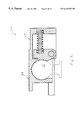
- FIG. 3 is a side view of an embodiment of the device, cut along cutting plane 2 — 2 , depicting the latching mechanism in the closed position.
- FIG. 4 is a side view of an embodiment of the device cut along cutting plane 2 — 2 , depicting the latching mechanism in the open position.
- FIG. 5 is a cutaway side view of an embodiment of the device showing a gooseneck adaptation.
- FIG. 6 is an oblique view of an embodiment of the device.
- FIG. 7 is an oblique view of an embodiment of the device, cut along cutting plane 7 — 7 .
- FIG. 8 is an oblique view of an embodiment of the device, cut along cutting plane 7 — 7 .
- FIG. 9 is an oblique view of an embodiment of the device.
- FIG. 10 is an oblique view of an embodiment of the device, cut along cutting plane 10 — 10 .
- FIG. 11 is a side view of an embodiment of the device.
- FIG. 12 is a top view of the embodiment shown in FIG. 11 .
- FIG. 13 is a side view of an embodiment of the device shown in FIG. 12, cut along cutting plane 13 — 13 depicting the latching mechanism in the closed position.
- FIG. 14 is an oblique view of an embodiment of the device.
- FIG. 15 is a rear view of the embodiment shown in FIG. 14, cut along cutting plane 15 — 15 .
- FIG. 16 is an oblique view of an embodiment of the device.
- FIG. 17 is an oblique view of an embodiment of the device showing a gooseneck adaptation.
- FIG. 18 is a side view of the embodiment shown in FIG. 18 .
- FIG. 19 is a top view of the embodiment shown in FIG. 17 .
- FIG. 20 is a rear view of the embodiment shown in FIG. 17 .
- FIG. 21 is a side view of the embodiment of the device shown in FIG. 17, cut along cutting plane 21 — 21 .
- FIG. 22 is a top view of the embodiment of the device shown in FIG. 17, including a cut away view of the added top structure.
- FIG. 23 is a side view of the embodiment of the device shown in FIG. 22, cut along cutting plane 23 — 23 .
- FIG. 24 is a bottom view of an embodiment of the device.
- FIG. 25 is a side view of the device shown in FIG. 24 .
- FIG. 26 is a side view of the embodiment shown in FIG. 24, cut along cutting plane 26 — 26 , depicting the latching mechanism in the closed position.
- FIG. 27 is a side view of the embodiment shown in FIG. 24, cut along cutting plane 26 — 26 , depicting the latching mechanism in the open position.
- FIG. 28 is a side view illustrating spatial relationships between the ball and the pivoting ball support pivot point.
- FIGS. 1-4 depict an embodiment of the device 10 , with FIGS. 3-4 showing a typical hitch ball 12 .
- FIGS. 2-4 show the configuration of the frame 14 , the frame front section interior 16 , the frame rear section interior 18 , and the frame opening 20 .
- the frame 14 can be made of a number of materials, including, but not limited to, cast steel, stainless steel, weldable steel, pressed steel, and mild steel. In the embodiment depicted in FIGS. 1-17 and 22 - 28 , cast steel has been chosen for the frame 14 .
- the embodiment depicted in FIGS. 24-27 utilizes pressed steel.
- FIGS. 2-4 depict additional frame features such as the frame lip 22 , the frame lip rearmost edge 24 , the frame lip face 26 , the frame front interior section interior surface rear part 28 , the frame front interior section interior surface rearmost edge 30 , the frame slot 32 , and the frame opening rear section 34 .
- the frame lip 22 extends radially around the front portion of the frame front section interior 16 , and is generally a continuation of the “dome” which forms the top of the frame front section interior 16 .
- the frame lip face 26 is somewhat concave, allowing a generally flush fit against a fully inserted hitch ball 12 .
- the frame front interior section interior surface rear part 28 extends approximately 62 degrees from vertical, and generally follows the circumference of the hitch ball 12 , as shown in FIGS. 3-4. In the embodiment depicted therein, a line drawn from the frame lip rearmost edge 24 to the frame front interior section interior surface rearmost edge 30 will pass beneath the center of a fully inserted hitch ball 12 .
- FIG. 1 depicts the position of the frame slot 32 with respect to the pivoting ball support 40 .
- the pivoting ball support 40 rotates with the pivoting ball support pivot point 42 from a first position, in which the pivoting ball support face 44 is in close proximity to the hitch ball 12 , to the second position, in which the pivoting ball support face 44 is dislocated, allowing the hitch ball 12 to be removed from the frame front section interior 16 through frame opening 20 .
- the pivoting ball support face 44 first position and second position are depicted in FIG. 3 and FIG. 4, respectively.
- FIGS. 1-4 depict an embodiment in which the ends of both springs are held in place by the first notch 50 and a second notch 52 cut into the frame rear section interior 18 and the pivoting ball support face 44 .
- Other embodiments could easily include springs 46 , 48 being attached to the frame rear section interior 18 and the pivoting ball support 40 , by normal attachment means, including screws, bolts, hooks, or welding.
- Embodiments are also anticipated that will use only one spring 46 , and one or more springs having a rod within the spring 46 , with an accompanying hole, for rod movement extending rearwardly into the frame 14 from the frame rear section interior 18 .
- springs 46 , 48 are substantially horizontal with respect to the frame 14 , in the embodiment depicted in FIGS. 2-4, other embodiments are anticipated which would place one or more such springs 46 , 48 in a non-horizontal position, including embodiments in which the springs 46 , 48 would have a bend provided, when the pivoting ball support face 44 is in its first position.
- FIGS. 2-4 also depict the pivoting ball support bottom end 54 , the pivoting ball support top extension 56 , and the pivoting ball support top extension hole 58 .
- a pin 60 connectable to the frame by a pin cable (not shown), will be against the frame 14 when inserted into pivoting ball support top extension hole 58 .
- Attached to the pin is a pin ring 62 which is sized to fit snugly against the unattached pin 60 end, as shown in FIG. 1 .
- pivoting ball support 40 will also be made of cast steel, although other materials will suffice as described earlier.
- a handle 70 which provides the means by which the pivoting ball support face 44 is rotated from its first position to its second position, to allow the hitch ball 12 to be removed from the device 10 .
- the handle 70 connects to the pivoting ball support pivot point 42 . It is anticipated in other embodiments that several types of handles will be utilized.
- Another anticipated embodiment includes a handle which is elevated from approximately 15 to 50 degrees from the horizontal when the pivoting ball support 40 is in its first position. This embodiment contemplates a sufficient angle from the horizontal to allow the handle to be gripped when the frame 14 is substantially flush to a horizontal object, which would otherwise prevent the handle from being gripped.
- Handle hooks can be anticipated to include a number of structures including semi-circular extensions from the frame that are positioned where the handle can be moved to rest within the semi-circle, thus having its movement restricted, squeeze clamps in which the handle shaft can be forced between the squeezing edges of such a clamp, a notch in the frame having an elevation at the entry which would prevent lateral movement of the handle without a preceding vertical movement, and other readily available means for securing a shaft in a fixed position.
- FIG. 5 shows a “gooseneck” adaptation 100 .
- the frame 102 has a top 104 connectable to a pipe typically used in gooseneck installations, where the upwardly extending pipe from the device 100 would telescope into another pipe, both pipes having appropriately spaced holes for adjustment of the height of the installed device.
- FIGS. 6-8 depict an additional embodiment 120 of the invention wherein the pivoting ball support 122 extends upwardly through a frame slot 124 such that the pivoting ball support 122 can be pushed by hand to move the pivoting ball support 122 from its first position to its second position.
- the pivoting ball support pivot point 131 may be welded or otherwise affixed to the frame 121 .
- FIG. 6 also depicts a frame top extension 126 having a hole 128 positioned adjacent the pivoting ball support top extension hole 130 , such that a pin or lock can be inserted simultaneously through both holes 128 , 130 , thus locking the pivoting ball support face 132 into its first position.
- An exterior frame lip 133 provides structural rigidity and assists in guiding the hitch ball during the hookup process.
- FIG. 8 depicts a U-spring 134 , which may be adapted to all embodiments of the invention.
- FIGS. 9-10 depict an embodiment 150 of the invention wherein the handle 152 is attached to the pivoting ball support 154 in such a manner that it is moved in an upward, clockwise direction in order to move the pivoting ball support 154 from its first position to its second position.
- FIGS. 11-13 depict an additional embodiment of the hitch 160 , which has been re-configured in some respects, from the embodiments of FIGS. 1-10. Furthermore, a cavity 162 is present in the frame 164 , which reduces the weight. Hollows 167 and 168 are formed in the pivoting ball support 169 and the frame rear interior section interior surface 170 , respectively. The hollows 167 , 168 receive the spring 171 first end 172 and second end 173 . An optional backup spring 174 is likewise secured. A pivoting ball support end portion 175 extends from the pivoting ball support top extension 176 , forming an acute angle with the frame 164 .
- Frame top extensions 177 , frame exterior lip 178 , frame interior lip 165 , and pivoting ball support top extension hole 179 are also shown.
- This embodiment of the hitch 160 appears to have the optimum configuration based on my current experience, although other adjustments to such configurations may occur to those of skill in the art after review of this disclosure.
- FIG. 14 depicts an embodiment 180 which includes the addition of channel structure 182 .
- the channel structure 182 attaches, or is adaptable for attachment, to the frame 14 , 121 , 156 , 164 of the embodiments shown in FIGS. 1-4 and 6 - 13 .
- the channel structure 182 extends rearwardly, and as shown in FIG. 15, has a rearwardly facing channel-shaped opening 184 sized to closely receive rectangular structure, e.g., square tubing (not shown) extending from the trailer.
- the square tubing or other rectangular structure may be welded or otherwise attached to the channel structure 182 .
- the channel structure 182 can be positioned with respect to the frame 14 , 121 , 156 , 164 such that the pivoting ball support pivot point 42 , 131 , 158 , 166 can be secured within the frame 14 , 121 , 156 , 164 in those embodiments wherein the pivoting ball support pivot point 42 , 131 , 158 , 160 extends, or can be extended, through the frame 14 , 121 , 156 , 164 such as those embodiments in FIGS. 1-4 and 6 - 13 .
- FIG. 16 depicts an embodiment 200 which includes an A-frame structure 202 .
- the A-frame structure 202 attaches, or is adaptable for attachment, to the frame 42 , 131 , 158 , 160 and extends rearwardly to closely receive trailer tongue structure (not shown).
- trailer tongue structure not shown.
- Other structures for joining my device to particular trailer structures will occur to those of skill in the art upon review of this disclosure.
- FIGS. 17-23 depict an additional “gooseneck” embodiments 210 and 240 .
- these embodiments include holes 212 , 214 in the frame 216 and pivoting ball support 218 which are aligned and sized for closely receiving a pin (not shown).
- An exterior frame lip 220 is also included.
- FIGS. 22-23 also depict vertical pipe structure 222 , which is included for the purposes described with regard to FIG. 5, above.
- the springs 224 shown in FIG. 21 are excluded from FIG. 23 such that a pivoting ball support stop 226 is revealed, which extends from one or both sides of the frame 228 .
- the extension is such that the pivoting ball support 218 rotation is halted by contact between the pivoting ball support 218 and one or more of the pivoting ball support stops 226 .
- a weld access opening 230 is originally present in the pivoting ball support 218 to allow the pivoting ball support 218 to be welded to the pivoting ball support pivot point 232 . It is anticipated that all, or substantially all of such welding access hole 230 will be filled by weld material.
- FIGS. 24-27 depict an additional embodiment 250 in which the frame 252 and the A-frame structure 254 are fashioned from pressed or stamped steel in a one-piece configuration.
- This configuration and manufacturing method will allow a simpler attachment of structures such as the A-frame structure 254 shown, and other structures for special trailer attachment requirements, such as the channel structure 182 shown in FIGS. 14-15. Such other structures, and the re-configurations of the hitch necessary to support this manufacturing method will occur to those skilled in the art upon review of this disclosure and as various trailer structures are presented for attachment.
- a pin 256 , pin chain 258 , and pin chain attachment point 260 are depicted on FIG. 25 .
- This configuration and manufacturing method also includes a structural lip 262 extending along the frame 252 and A-frame structure 254 . For clarity the spring(s) are not shown in FIGS. 24, 26 - 27 .
- FIG. 28 depicts a typical embodiment 270 illustrates relationship between R, X, and Y which is believed to provide functionally satisfactory results for all embodiments of my invention, including embodiments utilized to secure balls of varying sizes.
- R is the radius of the ball housing, i.e., that portion of the frame front interior section 272 which most closely receives the ball.
- the distances Y and X identify the position for the center of rotation of the pivoting ball support pivot point 274 .
- the identification of permissible tolerances in the relationship between R, X, and Y will occur to those of skill in the art after review of this disclosure.
- my invention will include the ball and/or the attachment structure to secure the ball to the portion of structure to be coupled.
- a wide variety of materials may be used for the components in any embodiment of my invention, particularly those embodiments used to couple lighter weight structures. Plastics, other metals, wood and other materials may be utilized. Other coupling applications will occur to those of skill in the art after review of this disclosure.
Landscapes
- Engineering & Computer Science (AREA)
- Transportation (AREA)
- Mechanical Engineering (AREA)
- Pivots And Pivotal Connections (AREA)
Abstract
Description
Claims (70)
Priority Applications (7)
| Application Number | Priority Date | Filing Date | Title |
|---|---|---|---|
| US09/271,015 US6419259B1 (en) | 1998-03-23 | 1999-03-17 | Device for receiving and securing a ball |
| US09/593,454 US6367834B1 (en) | 1998-03-23 | 2000-06-14 | Device for receiving and securing a ball |
| US09/761,968 US6505848B1 (en) | 1998-03-23 | 2001-01-17 | Device for receiving and securing a ball |
| US10/123,297 US6616169B1 (en) | 1998-03-23 | 2002-04-15 | Device for receiving and securing a ball |
| US10/124,173 US6523850B1 (en) | 1998-03-23 | 2002-04-16 | Device for receiving and securing a ball |
| US10/124,150 US6523849B1 (en) | 1998-03-23 | 2002-04-16 | Device for receiving and securing a ball |
| US10/253,982 US6811176B2 (en) | 1998-03-23 | 2002-09-24 | Device for receiving and securing a ball |
Applications Claiming Priority (3)
| Application Number | Priority Date | Filing Date | Title |
|---|---|---|---|
| US7899398P | 1998-03-23 | 1998-03-23 | |
| US11606099P | 1999-01-15 | 1999-01-15 | |
| US09/271,015 US6419259B1 (en) | 1998-03-23 | 1999-03-17 | Device for receiving and securing a ball |
Related Child Applications (4)
| Application Number | Title | Priority Date | Filing Date |
|---|---|---|---|
| US09/593,454 Continuation-In-Part US6367834B1 (en) | 1998-03-23 | 2000-06-14 | Device for receiving and securing a ball |
| US10/123,297 Division US6616169B1 (en) | 1998-03-23 | 2002-04-15 | Device for receiving and securing a ball |
| US10/124,150 Division US6523849B1 (en) | 1998-03-23 | 2002-04-16 | Device for receiving and securing a ball |
| US10/124,173 Division US6523850B1 (en) | 1998-03-23 | 2002-04-16 | Device for receiving and securing a ball |
Publications (1)
| Publication Number | Publication Date |
|---|---|
| US6419259B1 true US6419259B1 (en) | 2002-07-16 |
Family
ID=27373391
Family Applications (4)
| Application Number | Title | Priority Date | Filing Date |
|---|---|---|---|
| US09/271,015 Expired - Lifetime US6419259B1 (en) | 1998-03-23 | 1999-03-17 | Device for receiving and securing a ball |
| US10/123,297 Expired - Fee Related US6616169B1 (en) | 1998-03-23 | 2002-04-15 | Device for receiving and securing a ball |
| US10/124,150 Expired - Fee Related US6523849B1 (en) | 1998-03-23 | 2002-04-16 | Device for receiving and securing a ball |
| US10/124,173 Expired - Fee Related US6523850B1 (en) | 1998-03-23 | 2002-04-16 | Device for receiving and securing a ball |
Family Applications After (3)
| Application Number | Title | Priority Date | Filing Date |
|---|---|---|---|
| US10/123,297 Expired - Fee Related US6616169B1 (en) | 1998-03-23 | 2002-04-15 | Device for receiving and securing a ball |
| US10/124,150 Expired - Fee Related US6523849B1 (en) | 1998-03-23 | 2002-04-16 | Device for receiving and securing a ball |
| US10/124,173 Expired - Fee Related US6523850B1 (en) | 1998-03-23 | 2002-04-16 | Device for receiving and securing a ball |
Country Status (1)
| Country | Link |
|---|---|
| US (4) | US6419259B1 (en) |
Cited By (2)
| Publication number | Priority date | Publication date | Assignee | Title |
|---|---|---|---|---|
| US7690673B1 (en) * | 2005-12-01 | 2010-04-06 | Dethmers Manufacturing Company | Self-latching ball clamp coupler |
| WO2015148197A1 (en) * | 2014-03-24 | 2015-10-01 | K-12, Llc | Removable trailer tow hitch |
Families Citing this family (4)
| Publication number | Priority date | Publication date | Assignee | Title |
|---|---|---|---|---|
| AU2003297418A1 (en) * | 2002-12-19 | 2004-07-14 | Master Lock Company | Adjustable width coupler latch lock |
| US8235411B2 (en) | 2008-10-13 | 2012-08-07 | B&W Custom Truck Beds, Inc. | Self-latching and locking trailer coupler |
| US7954840B2 (en) * | 2008-10-15 | 2011-06-07 | U-Haul International, Inc. | Coupler assembly with guided ball clamp |
| CN109466256B (en) * | 2018-10-24 | 2021-07-20 | 江苏大学 | Pull type recreational vehicle spherical connecting system and control method thereof |
Citations (17)
| Publication number | Priority date | Publication date | Assignee | Title |
|---|---|---|---|---|
| US1953365A (en) | 1932-05-23 | 1934-04-03 | August W Reetz | Trailer coupling |
| US2078851A (en) | 1935-10-23 | 1937-04-27 | Smith D Hovey | Hitch |
| US2090113A (en) | 1934-09-22 | 1937-08-17 | Bamax Machine Co Inc | Trailer hitch |
| US2178094A (en) * | 1936-07-09 | 1939-10-31 | Max E Dayton | Trailer hitch |
| US2204882A (en) * | 1939-01-21 | 1940-06-18 | Ercole R Berluti | Trailer hitch |
| US2237166A (en) * | 1940-03-01 | 1941-04-01 | George B Schoenrock | Trailer hitch |
| US2435024A (en) * | 1945-10-10 | 1948-01-27 | Carl J Wagner | Trailer hitch |
| US2532676A (en) * | 1947-05-09 | 1950-12-05 | Active Tool & Mfg Company | Trailer hitch |
| US2542643A (en) | 1947-09-06 | 1951-02-20 | John O Duncan | Trailer hitch |
| US2726099A (en) * | 1955-03-03 | 1955-12-06 | Crane Co H W | Ball and socket hitch with automatic safety latch |
| US3362728A (en) | 1966-04-11 | 1968-01-09 | Cyrus L. Wing | Hitch construction |
| US3677564A (en) * | 1970-03-27 | 1972-07-18 | Gilbert C Kothmann | Safety trailer hitch |
| US3888517A (en) * | 1973-11-16 | 1975-06-10 | James D Ray | Trailer hitching coupler |
| US3923112A (en) * | 1974-01-07 | 1975-12-02 | Muriel T Goodgame | Driven wheel arrangement |
| FR2420441A1 (en) * | 1978-03-23 | 1979-10-19 | Goett & Cie Ets | Tow ball point assembly for trailer - has cup automatically clamped closed by return spring and opened by external hand grip |
| GB2056929A (en) * | 1979-08-21 | 1981-03-25 | Winterhoff U | A coupling apparatus |
| US5147096A (en) | 1991-10-25 | 1992-09-15 | Rogers Gerald H | Easy latch and unlatch cam action trailer hitch |
Family Cites Families (4)
| Publication number | Priority date | Publication date | Assignee | Title |
|---|---|---|---|---|
| US1254199A (en) * | 1916-05-22 | 1918-01-22 | Milton D Brice | Pole-coupling. |
| US2580770A (en) * | 1950-05-15 | 1952-01-01 | Charles M Harris | Hitch |
| US3647244A (en) | 1970-01-12 | 1972-03-07 | Gen Processing Corp | Coupler for trailers and the like |
| US5887885A (en) | 1997-02-06 | 1999-03-30 | Byers; Dwight R. | Self-locking trailer hitch assembly |
-
1999
- 1999-03-17 US US09/271,015 patent/US6419259B1/en not_active Expired - Lifetime
-
2002
- 2002-04-15 US US10/123,297 patent/US6616169B1/en not_active Expired - Fee Related
- 2002-04-16 US US10/124,150 patent/US6523849B1/en not_active Expired - Fee Related
- 2002-04-16 US US10/124,173 patent/US6523850B1/en not_active Expired - Fee Related
Patent Citations (17)
| Publication number | Priority date | Publication date | Assignee | Title |
|---|---|---|---|---|
| US1953365A (en) | 1932-05-23 | 1934-04-03 | August W Reetz | Trailer coupling |
| US2090113A (en) | 1934-09-22 | 1937-08-17 | Bamax Machine Co Inc | Trailer hitch |
| US2078851A (en) | 1935-10-23 | 1937-04-27 | Smith D Hovey | Hitch |
| US2178094A (en) * | 1936-07-09 | 1939-10-31 | Max E Dayton | Trailer hitch |
| US2204882A (en) * | 1939-01-21 | 1940-06-18 | Ercole R Berluti | Trailer hitch |
| US2237166A (en) * | 1940-03-01 | 1941-04-01 | George B Schoenrock | Trailer hitch |
| US2435024A (en) * | 1945-10-10 | 1948-01-27 | Carl J Wagner | Trailer hitch |
| US2532676A (en) * | 1947-05-09 | 1950-12-05 | Active Tool & Mfg Company | Trailer hitch |
| US2542643A (en) | 1947-09-06 | 1951-02-20 | John O Duncan | Trailer hitch |
| US2726099A (en) * | 1955-03-03 | 1955-12-06 | Crane Co H W | Ball and socket hitch with automatic safety latch |
| US3362728A (en) | 1966-04-11 | 1968-01-09 | Cyrus L. Wing | Hitch construction |
| US3677564A (en) * | 1970-03-27 | 1972-07-18 | Gilbert C Kothmann | Safety trailer hitch |
| US3888517A (en) * | 1973-11-16 | 1975-06-10 | James D Ray | Trailer hitching coupler |
| US3923112A (en) * | 1974-01-07 | 1975-12-02 | Muriel T Goodgame | Driven wheel arrangement |
| FR2420441A1 (en) * | 1978-03-23 | 1979-10-19 | Goett & Cie Ets | Tow ball point assembly for trailer - has cup automatically clamped closed by return spring and opened by external hand grip |
| GB2056929A (en) * | 1979-08-21 | 1981-03-25 | Winterhoff U | A coupling apparatus |
| US5147096A (en) | 1991-10-25 | 1992-09-15 | Rogers Gerald H | Easy latch and unlatch cam action trailer hitch |
Cited By (3)
| Publication number | Priority date | Publication date | Assignee | Title |
|---|---|---|---|---|
| US7690673B1 (en) * | 2005-12-01 | 2010-04-06 | Dethmers Manufacturing Company | Self-latching ball clamp coupler |
| WO2015148197A1 (en) * | 2014-03-24 | 2015-10-01 | K-12, Llc | Removable trailer tow hitch |
| US9862243B2 (en) | 2014-03-24 | 2018-01-09 | K-12, Llc | Removable trailer tow hitch |
Also Published As
| Publication number | Publication date |
|---|---|
| US6616169B1 (en) | 2003-09-09 |
| US6523849B1 (en) | 2003-02-25 |
| US6523850B1 (en) | 2003-02-25 |
Similar Documents
| Publication | Publication Date | Title |
|---|---|---|
| USRE35482E (en) | Towing hitch | |
| US7478821B2 (en) | Pintle hitch adaptor for drawbar or DMI bumper | |
| US5806872A (en) | Trailer hitch assembly | |
| US6467793B2 (en) | Gooseneck coupler | |
| US6485045B1 (en) | Combination fifth wheel and gooseneck hitch | |
| US5261687A (en) | Automatic hitch assembly | |
| US7506885B2 (en) | Load-leveling, weight-distributing hitch system | |
| US5121862A (en) | Cycle rack | |
| US4869521A (en) | Collapsible towing hitch | |
| US4792153A (en) | Trailer hitch | |
| US20230322031A1 (en) | Hitch Assembly | |
| US6908093B1 (en) | Kingpin coupler | |
| US6811176B2 (en) | Device for receiving and securing a ball | |
| US6095545A (en) | Positive lock gooseneck hitch | |
| US6419259B1 (en) | Device for receiving and securing a ball | |
| US6637765B2 (en) | Towing safety device | |
| CA1268794A (en) | Trailer hitching aid | |
| US5441295A (en) | Lock assembly for a trailer hitch | |
| US7055845B1 (en) | Adjustable hitch | |
| CA2302335C (en) | Adjustable coupler for a weight distributing trailer hitch apparatus | |
| US6902182B1 (en) | Hitch device | |
| US6367834B1 (en) | Device for receiving and securing a ball | |
| US20030080263A1 (en) | Accessory mounting adapter for a trailer hitch assembly | |
| US6086298A (en) | Clamping device for securing recreational vehicle or appliance | |
| US20060076755A1 (en) | Automatic hitch system |
Legal Events
| Date | Code | Title | Description |
|---|---|---|---|
| AS | Assignment |
Owner name: D. R. BROWN CORPORATION, TEXAS Free format text: LICENSE AGREEMENT;ASSIGNORS:BROWN, DAVID R.;BROWN, LINDA;BROWN, STACY;AND OTHERS;REEL/FRAME:012751/0685 Effective date: 20001016 |
|
| STCF | Information on status: patent grant |
Free format text: PATENTED CASE |
|
| AS | Assignment |
Owner name: VAQUILLAS INVESTMENTS, LTD., TEXAS Free format text: SHERIFFS BILL OF SALE;ASSIGNOR:D.R. BROWN CORPORATION;REEL/FRAME:013347/0120 Effective date: 20020304 |
|
| AS | Assignment |
Owner name: GUERRA, PEPE, TRUSTEE, TEXAS Free format text: ASSIGNMENT OF ASSIGNORS INTEREST;ASSIGNORS:FLEEMAN, BILL;BROWN, DAVID R.;REEL/FRAME:013514/0309 Effective date: 20020204 Owner name: PEPE GUERRA, TRUSTEE, TEXAS Free format text: ASSIGNMENT OF ASSIGNORS INTEREST;ASSIGNOR:BROWN, LINDA;REEL/FRAME:013514/0319 Effective date: 20020228 |
|
| AS | Assignment |
Owner name: FLEEMAN, BILL, TEXAS Free format text: FINAL JUDGMENT;ASSIGNORS:BROWN, DAVID RICHARD;BROWN, DANNY RICHARD;BROWN, STACY RAY;REEL/FRAME:014588/0005 Effective date: 20020213 Owner name: PEPE GUERRA, TRUSTEE, TEXAS Free format text: MUTUAL RELEASE AND SETTLEMENT AGREEMENT;ASSIGNOR:FLEEMAN, BILL;REEL/FRAME:014588/0008 Effective date: 20020312 |
|
| FPAY | Fee payment |
Year of fee payment: 4 |
|
| AS | Assignment |
Owner name: FLEEMAN, BILL, TEXAS Free format text: ASSIGNMENT OF ASSIGNORS INTEREST;ASSIGNOR:GUERRA, JOSE L.;REEL/FRAME:022584/0320 Effective date: 20090410 |
|
| REMI | Maintenance fee reminder mailed | ||
| FPAY | Fee payment |
Year of fee payment: 8 |
|
| SULP | Surcharge for late payment |
Year of fee payment: 7 |
|
| REMI | Maintenance fee reminder mailed | ||
| FPAY | Fee payment |
Year of fee payment: 12 |
|
| SULP | Surcharge for late payment |
Year of fee payment: 11 |