US641663A - Telephone. - Google Patents
Telephone. Download PDFInfo
- Publication number
- US641663A US641663A US66926398A US1898669263A US641663A US 641663 A US641663 A US 641663A US 66926398 A US66926398 A US 66926398A US 1898669263 A US1898669263 A US 1898669263A US 641663 A US641663 A US 641663A
- Authority
- US
- United States
- Prior art keywords
- receiver
- switch
- telephone
- transmitter
- support
- Prior art date
- Legal status (The legal status is an assumption and is not a legal conclusion. Google has not performed a legal analysis and makes no representation as to the accuracy of the status listed.)
- Expired - Lifetime
Links
- 238000010276 construction Methods 0.000 description 1
- 230000000694 effects Effects 0.000 description 1
- 210000003141 lower extremity Anatomy 0.000 description 1
- 230000000284 resting effect Effects 0.000 description 1
Images
Classifications
-
- H—ELECTRICITY
- H04—ELECTRIC COMMUNICATION TECHNIQUE
- H04M—TELEPHONIC COMMUNICATION
- H04M1/00—Substation equipment, e.g. for use by subscribers
- H04M1/02—Constructional features of telephone sets
- H04M1/11—Supports for sets, e.g. incorporating armrests
Definitions
- the invent-ion consists, essentially, in an auxiliary weight connected with the switch and operated and controlled by mechanism actuated by the transmitter-support, so that the drawing of the latter into position for use cuts out the alarm, while the pushing back of the receiver disconnects the said receiver and throws the alarm into circuit, both operations being automatic,s0 far as the actuation of the switch is concerned, and the parts being constructed and arranged substantially as herein described and claimed.
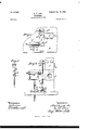
- Figure 1 is a plan of a portion ofa table supporting parts embodying my invention.
- Fig. 2 is a front elevation of the. same, the parts being in position in which the call is disconnected and the receiver thrown into circuit.
- Fig. 3 is a similar View showing the part-s as situated when the receiver is disconnected and the call thrown into circuit.
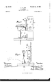
- Fig. 4 is a side elevation.
- Fig. 5 is a sectional detail of the weight.
- A is a call-box of any ordinary construction, T the transmitter device, and C the reapplications, Serial No. 664,821, filed Decem ber 81, 1897, and Serial No. 664,626, filed De cember 30, 1897.
- the bifurcated arms 8 s are attached to a standard 8, which is adjustable vertically upon a sliding base or support B, by means of a set-screw 5 the table or other support D being formed with a longitudinal slot 6 to accommodate the lower end of the said standards 5.
- the base or.s1id e 1 3 is held laterally upon the table or support D by rabbets or guides d and is provided with an inclined plane 01 separating an upper plane 01 and a lower plane 61
- the supplementary weight W may be made to represent in external configuration more or less the transmitter T and is designed to be hung on the switch a in a like manner.
- the lower end of the weight W is formed with a recess w for the reception of the upper end 1' of the vertical rod R, the opposite or lower extremity of which is provided with a roller 1", resting or traveling upon the planes (1 (1 A guiding and stead yingarmorbracketE may be provided for the rod R, or equivalent means of support may be furnished.
- the sliding base B formed with the inclined 2o plane (1 interposed between the upper and lower planes d d the receiver-support S,
Landscapes
- Engineering & Computer Science (AREA)
- Signal Processing (AREA)
- Telephone Set Structure (AREA)
- Mobile Radio Communication Systems (AREA)
Description
No. 64!,663. Patented Ian. l6, I900.
' A. A. LOW.
TELEPHONE.
(Application filed Feb. 5, 1898.)
2 Shuts-Sheet I.
(No Model.)
Mvwkmm Qimwasms.
MW M410 .1.
III I No. 64l ,663. Patented Ian. I6, I900. 1 A. A. LOW. E 1
TELEPHONE.
(Application filed Feb. 6 1898A (No Modal.) 2 Sheets-:Sheet 2.
UNrTED STATES PATENT OFFICE.
ABBOT AUGUSTUS LOW, OF NFAV YORK, N. Y.
TELEPHONE.
SPECIFICATION forming part of Letters Patent No. 641,663, dated January 16-, 1900.
Application filed February 5, 1898. Serial No. 669,263- (No model.)
. To all whom it may concern.-
eral use in which an automatic switch is used.
' to cut out the call and throw the receiver into circuit, the act of lifting the receiver from the switch being relied on to effect the result. I design to obviate the necessity for lifting the receiver from the switch, and to support the receiver under normal conditionsin such manner that it may be quickly drawn into position with relation to the transmitter, at the same time si on ulta-neousl y releasing the switch automatically, so as to disconnect the alarm and connect the transmitter.
Although this invention may be applied to 2 5 .various forms and arrangements of telephones and receivers, I have designed and shown it herein as specially adapted to the requirements of telephones already in use.
The invent-ion consists, essentially, in an auxiliary weight connected with the switch and operated and controlled by mechanism actuated by the transmitter-support, so that the drawing of the latter into position for use cuts out the alarm, while the pushing back of the receiver disconnects the said receiver and throws the alarm into circuit, both operations being automatic,s0 far as the actuation of the switch is concerned, and the parts being constructed and arranged substantially as herein described and claimed.
In the accompanying drawings, Figure 1 is a plan of a portion ofa table supporting parts embodying my invention. Fig. 2 is a front elevation of the. same, the parts being in position in which the call is disconnected and the receiver thrown into circuit. Fig. 3 is a similar View showing the part-s as situated when the receiver is disconnected and the call thrown into circuit. Fig. 4 is a side elevation. Fig. 5 is a sectional detail of the weight.
A is a call-box of any ordinary construction, T the transmitter device, and C the reapplications, Serial No. 664,821, filed Decem ber 81, 1897, and Serial No. 664,626, filed De cember 30, 1897.
As shown in the drawings, the bifurcated arms 8 s are attached to a standard 8, which is adjustable vertically upon a sliding base or support B, by means of a set-screw 5 the table or other support D being formed with a longitudinal slot 6 to accommodate the lower end of the said standards 5.
The base or.s1id e 1 3 is held laterally upon the table or support D by rabbets or guides d and is provided with an inclined plane 01 separating an upper plane 01 and a lower plane 61 The supplementary weight W may be made to represent in external configuration more or less the transmitter T and is designed to be hung on the switch a in a like manner. The lower end of the weight W is formed with a recess w for the reception of the upper end 1' of the vertical rod R, the opposite or lower extremity of which is provided with a roller 1", resting or traveling upon the planes (1 (1 A guiding and stead yingarmorbracketE may be provided for the rod R, or equivalent means of support may be furnished.
The operation is as follows: The parts being in the position shown in Figs. 1, 3, and 4, the person desiring to use the telephone draws forward the base B by means of the handle 19 or other suitable device until the receiver 0 is in proper relation horizontally to the transmitter T-that is, so that the receiver will be in convenient proximity to the ear of the user when his mouth is in proper relation to the transmitter. This action draws the inclined plane 01 under and beyond the roller r upon the lower end of the rod R, so that said roller rests upon the upper plane d the rod in the meantime having raised the weight \V sufiiciently to release the switch av and allow it to act automatically in throwing the receiver in circuit. After use the pushing back of the receiver-slide B causes the roller 7" to again descend the incline d onto the lower plane 61 thereby withdrawing the upper end 0 of the rod R from the auxiliary weight \V,which thus presses down the switch a, disconnecting the receiver and throwing the alarm or call device into circuit.
lVhat I claim as my invention, and desire to secure by Letters Patent, is-
In a telephone the combination with a transmitter T, alarm A, provided with the automatic switch a, the auxiliary weight XV, the lifting-rod R, provided with the roller 1*,
the sliding base B, formed with the inclined 2o plane (1 interposed between the upper and lower planes d d the receiver-support S,
and said receiver 0, the whole arranged and operating substantially in the manner and for the purpose described.
ABBOT AUGUSTUS LOlV.
Witnesses:
D. W. GARDNER, FLORENCE MIATT.
Priority Applications (1)
| Application Number | Priority Date | Filing Date | Title |
|---|---|---|---|
| US66926398A US641663A (en) | 1898-02-05 | 1898-02-05 | Telephone. |
Applications Claiming Priority (1)
| Application Number | Priority Date | Filing Date | Title |
|---|---|---|---|
| US66926398A US641663A (en) | 1898-02-05 | 1898-02-05 | Telephone. |
Publications (1)
| Publication Number | Publication Date |
|---|---|
| US641663A true US641663A (en) | 1900-01-16 |
Family
ID=2710246
Family Applications (1)
| Application Number | Title | Priority Date | Filing Date |
|---|---|---|---|
| US66926398A Expired - Lifetime US641663A (en) | 1898-02-05 | 1898-02-05 | Telephone. |
Country Status (1)
| Country | Link |
|---|---|
| US (1) | US641663A (en) |
Cited By (1)
| Publication number | Priority date | Publication date | Assignee | Title |
|---|---|---|---|---|
| US20100102685A1 (en) * | 2008-10-28 | 2010-04-29 | John William Ward | Chambered cremation URN memorial with attached or integrated electronic imaging device |
-
1898
- 1898-02-05 US US66926398A patent/US641663A/en not_active Expired - Lifetime
Cited By (1)
| Publication number | Priority date | Publication date | Assignee | Title |
|---|---|---|---|---|
| US20100102685A1 (en) * | 2008-10-28 | 2010-04-29 | John William Ward | Chambered cremation URN memorial with attached or integrated electronic imaging device |
Similar Documents
| Publication | Publication Date | Title |
|---|---|---|
| US641663A (en) | Telephone. | |
| US2473106A (en) | Telephone handset supporting fixture | |
| US1099820A (en) | Combined camera-support and posing device. | |
| US3458666A (en) | Hook switch arrangement for wall telephones | |
| US615344A (en) | Parent office | |
| US854439A (en) | Portable combination telephone set. | |
| US757257A (en) | Telephone-receiver support. | |
| US980619A (en) | Locking device for the receiver-arms of telephones. | |
| US950937A (en) | Disinfectant device for telephones. | |
| US3662109A (en) | Handset lifter | |
| US1341280A (en) | Telephone hand set or hand piece | |
| US3480741A (en) | Vertical hanging attachment for telephones | |
| US545253A (en) | shaver | |
| US1681754A (en) | Telephone stand or equipment | |
| US561423A (en) | Paul minnis | |
| US1119366A (en) | Support for telephone-receivers. | |
| US501405A (en) | bubchell | |
| US761150A (en) | Telephone attachment. | |
| US862497A (en) | Holder for telephone-receivers. | |
| US3179751A (en) | Telephone instruments | |
| US238019A (en) | Telephone-switch | |
| US400911A (en) | Telephone-support | |
| US796341A (en) | Lemon-squeezer. | |
| US841491A (en) | Telephone. | |
| US1454533A (en) | Support for telephone receivers |