US6400357B1 - Method for assembling the rubber dome into the keyboard and the keyboard thereof - Google Patents
Method for assembling the rubber dome into the keyboard and the keyboard thereof Download PDFInfo
- Publication number
- US6400357B1 US6400357B1 US09/192,976 US19297698A US6400357B1 US 6400357 B1 US6400357 B1 US 6400357B1 US 19297698 A US19297698 A US 19297698A US 6400357 B1 US6400357 B1 US 6400357B1
- Authority
- US
- United States
- Prior art keywords
- upper casing
- hook
- circuit sheet
- rubber
- membrane circuit
- Prior art date
- Legal status (The legal status is an assumption and is not a legal conclusion. Google has not performed a legal analysis and makes no representation as to the accuracy of the status listed.)
- Expired - Fee Related
Links
Images


Classifications
-
- H—ELECTRICITY
- H01—ELECTRIC ELEMENTS
- H01H—ELECTRIC SWITCHES; RELAYS; SELECTORS; EMERGENCY PROTECTIVE DEVICES
- H01H13/00—Switches having rectilinearly-movable operating part or parts adapted for pushing or pulling in one direction only, e.g. push-button switch
- H01H13/70—Switches having rectilinearly-movable operating part or parts adapted for pushing or pulling in one direction only, e.g. push-button switch having a plurality of operating members associated with different sets of contacts, e.g. keyboard
- H01H13/702—Switches having rectilinearly-movable operating part or parts adapted for pushing or pulling in one direction only, e.g. push-button switch having a plurality of operating members associated with different sets of contacts, e.g. keyboard with contacts carried by or formed from layers in a multilayer structure, e.g. membrane switches
-
- G—PHYSICS
- G06—COMPUTING OR CALCULATING; COUNTING
- G06F—ELECTRIC DIGITAL DATA PROCESSING
- G06F3/00—Input arrangements for transferring data to be processed into a form capable of being handled by the computer; Output arrangements for transferring data from processing unit to output unit, e.g. interface arrangements
- G06F3/01—Input arrangements or combined input and output arrangements for interaction between user and computer
- G06F3/02—Input arrangements using manually operated switches, e.g. using keyboards or dials
- G06F3/0202—Constructional details or processes of manufacture of the input device
-
- H—ELECTRICITY
- H01—ELECTRIC ELEMENTS
- H01H—ELECTRIC SWITCHES; RELAYS; SELECTORS; EMERGENCY PROTECTIVE DEVICES
- H01H2207/00—Connections
- H01H2207/004—Printed circuit tail
-
- H—ELECTRICITY
- H01—ELECTRIC ELEMENTS
- H01H—ELECTRIC SWITCHES; RELAYS; SELECTORS; EMERGENCY PROTECTIVE DEVICES
- H01H2215/00—Tactile feedback
- H01H2215/004—Collapsible dome or bubble
- H01H2215/012—Positioning of individual dome
-
- H—ELECTRICITY
- H01—ELECTRIC ELEMENTS
- H01H—ELECTRIC SWITCHES; RELAYS; SELECTORS; EMERGENCY PROTECTIVE DEVICES
- H01H2229/00—Manufacturing
- H01H2229/034—Positioning of layers
Definitions
- the invention relates to a method for assembling the rubber dome into the keyboard and the structure of the keyboard associating with the method.
- the keyboard mainly includes, other than a plurality of key caps, a plurality of robber domes, an upper casing, a membrane circuit sheet and a lower casing.
- a plurality of housings are formed simultaneously.
- Each housing is used to receive a key cap and a rubber dome.
- the structure of each push button switch of keyboard includes a key cap, a rubber dome which turns on a corresponding membrane switch on the membrane circuit sheet then the key cap is depressed.
- the rubber dome is disposed into the housing from the side of the bottom surface of the upper casing.
- the key cap is disposed into the housing from the side of the top surface.
- the top surface of the keyboard is the surface facing the user.
- the bottom surface of the keyboard is the surface opposite to the top surface and faces the lower casing of the keyboard.
- the function of each component of the push button switch is well known in the arts.
- One type is in form of an integral sheet with a multiple of rubber domes formed thereon and another type is in form of a single rubber dome isolated from other rubber domes within other housings.
- Integral sheet type rubber domes are formed by producing a plurality of (around 125) of rubber domes at the same time integrally. Each rubber dome is connected to each other by an integral rubber sheet during production.
- the advantage of the integral sheet type is its capability of disposing each of all rubber domes into their corresponding housings by single operation.
- more than half of the rubber material of the integral sheet type rubber domes is for connection purpose and wasted.
- a single rubber dome configuration mentioned above is adopted.
- Another way is first pouring a multiple of rubber domes over the bottom surface of upper casing. Afterwards, a human or a mechanical vibration action is input to dispose each rubber dome over the bottom surface of upper casing into one corresponding housing. At the end of the procedure, a number of rubber domes are leftover and no received in any one of the housings. If some housings do not have one rubber dome therein, the operator then feeds the rubber dome by hand into the empty housings. The leftover rubber domes located at positions other than housings are also picked up and removed by operator. The procedure spent on the removal of the leftover rubber domes is timing consuming and cost ineffective.
- the present invention provides a method and a keyboard thereof which quickly removes the leftover rubber domes and therefore improves the assembly efficiency of the rubber domes.
- the upper casing of the keyboard of the invention defines a bottom surface and a top surface and includes a multiple of housings distributed over a central portion of the bottom surface. Each housing receives one rubber dome.
- the method includes the steps of pouring a plurality of rubber domes over the bottom surface of the upper casing; shaking the upper casing in order to dispose one rubber dome into one corresponding housing while a number of rubber domes are leftover and not received in any one of the housings; engaging a membrane circuit sheet with the central portion of the bottom surface; flipping the upper casing over such that the leftover rubber domes not covered by the membrane circuit sheet are cleaned up.
- FIG. 1 shows a perspective view of the upper casing of keyboard, in accordance with the invention, taken from the side of the bottom surface of the keyboard.
- FIG. 2 shows the membrane circuit sheet in corporation with the upper casing in FIG. 1 .
- FIG. 3 shows how the membrane circuit sheet engages with the upper casing.
- FIG. 4 shows the perspective view of upper casing of keyboard as the membrane circuit sheet is assembled.
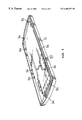
- FIG. 5 shows the second embodiment of the invention.
- the keyboard upper casing 10 is substantially in form of a shell shape and includes a plurality of housings distributed over a central portion 12 of the bottom surface. Each housing is used to receive a rubber dome and a key cap. The rubber dome is disposed into the housing from the side of the bottom surface of the upper casing. On the other hand, the key cap is disposed into the housing from the side of the top surface of the upper casing. Furthermore, as shown, a surrounding channel is formed between the sides of the upper casing 10 and the central portion 12 over which a plurality of housings are distributed.
- the central portion 12 of the bottom surface of the upper casing 10 includes a multiple of hook apparatuses.
- the hook apparatuses are classified as the first set of hook devices 14 and the second set of hook devices 16 .
- Each hook device 14 has a hook end orienting to the right and each hook device 16 has a hook end orienting to the left.
- the hook device 14 has a hook end orienting to the left and the hook device 16 has a hook end orienting to the right.
- the upper casing 10 is first disposed on the operation bench with the bottom surface facing upward to undergo the operation of pouring a plurality of rubber domes over the bottom surface of upper casing 10 . Afterwards, a human or a mechanical vibration action is input in order to dispose one rubber dome into one corresponding housing. Alternatively, a wiping device, e.g. a swivel brush, is used to dispose most of the rubber domes into their corresponding housings. At the end of the procedure, a number of rubber domes 15 are leftover and not received in any one of the housings. If some housings do not have one rubber dome therein, the operator then feeds the rubber dome by hand into the empty housing. The leftover rubber domes 15 located at positions other than housings, as shown in FIG. 1, has to be removed.
- a wiping device e.g. a swivel brush
- the contour of the membrane circuit sheet 20 provided by the invention substantially follows the contour of the central portion 12 of the bottom surface of the upper casing 10 .
- the membrane circuit sheet 20 includes a plurality of slots 22 each of which corresponds one hook 14 or 16 .
- the membrane circuit sheet 20 is forced to displace leftward by a small amount and this action allows the slots 22 at the left hand side pass the hook devices 16 and effect the connection of the slots 22 at the left hand side to the hook devices 16 .
- FIG. 4 The status of the upper casing 10 and membrane circuit sheet 20 , after the above procedure is completed, is shown in FIG. 4 . At this time, the rubber dome within each housing is covered and retained by the membrane circuit sheet 20 . However, the leftover domes 15 within the surrounding channel of the upper casing 10 are not retained by the membrane circuit sheet 20 .
- the membrane circuit sheet 20 is a requisite of the keyboard device, by providing a novel structures on the upper casing 10 and the membrane circuit sheet 20 , the invention resolves the drawbacks of the conventional approaches. No new device or element is needed.
- the purpose of the cut line 24 provided within the membrane circuit sheet 20 , shown in FIG. 2, is to allow the membrane portion 26 adjacent to the cut line 24 to be uncoverable.
- the provision of the cut line 24 and the uncoverable membrane portion 26 are directed to the concave space 18 at the upper left corner of the upper casing 10 in FIG. 1 .
- the concave space 18 is provided to accommodate the printed circuit board implementing the control circuit of the keyboard.
- the finger array (not shown) of the print circuit board is connected to the printed finger array (not shown) distributed along the cut line 24 of uncoverable membrane portion 26 .
- the concave space 18 due to the existence of the concave space 18 , there might be some leftover rubber domes 15 within this concave space 18 other than leftover rubber domes 15 within the surrounding channel of the upper casing 10 .
- the leftover rubber domes 15 within this concave space 18 and under the uncoverable membrane portion 26 can drop from the cut line 24 and can be cleaned up easily.
- the second embodiment of the invention is shown in FIG. 5 .
- the upper casing 10 is characterized in that the edge of the central portion of bottom surface of the upper casing 10 provides a multiple of hook devices 54 for engaging a membrane circuit sheet 50 .
- the hook end of each hook device 54 is orienting to the central portion of bottom surface.
- the membrane circuit sheet 50 Before disposing the membrane circuit sheet 50 , one needs to deform the membrane circuit sheet 50 slightly such that the edges of membrane circuit sheet 50 can be inserted into the space defined by the hook end of hook 54 . After the force is released, the membrane circuit sheet 50 resumes its original shape, the multiple of hook devices 54 then engage the edges of membrane circuit sheet 50 .
- This embodiment also achieves the object of the invention.
Landscapes
- Engineering & Computer Science (AREA)
- General Engineering & Computer Science (AREA)
- Theoretical Computer Science (AREA)
- Human Computer Interaction (AREA)
- Physics & Mathematics (AREA)
- General Physics & Mathematics (AREA)
- Input From Keyboards Or The Like (AREA)
Abstract
Description
Claims (13)
Applications Claiming Priority (2)
| Application Number | Priority Date | Filing Date | Title |
|---|---|---|---|
| TW87112918A | 1998-08-05 | ||
| TW087112918A TW387079B (en) | 1998-08-05 | 1998-08-05 | Method of assembling rubber dome in a keyboard and structure of the keyboard |
Publications (1)
| Publication Number | Publication Date |
|---|---|
| US6400357B1 true US6400357B1 (en) | 2002-06-04 |
Family
ID=21630920
Family Applications (1)
| Application Number | Title | Priority Date | Filing Date |
|---|---|---|---|
| US09/192,976 Expired - Fee Related US6400357B1 (en) | 1998-08-05 | 1998-11-16 | Method for assembling the rubber dome into the keyboard and the keyboard thereof |
Country Status (2)
| Country | Link |
|---|---|
| US (1) | US6400357B1 (en) |
| TW (1) | TW387079B (en) |
Cited By (6)
| Publication number | Priority date | Publication date | Assignee | Title |
|---|---|---|---|---|
| US6776547B1 (en) * | 1999-08-24 | 2004-08-17 | Fujitsu Siemans Computers Gmbh | Keyboard housing for a keypad of a push-button keyboard |
| US20100078303A1 (en) * | 2008-09-29 | 2010-04-01 | Microsoft Corporation | Mechanical architecture for display keyboard keys |
| US20100214135A1 (en) * | 2009-02-26 | 2010-08-26 | Microsoft Corporation | Dynamic rear-projected user interface |
| US20220157153A1 (en) * | 2019-03-18 | 2022-05-19 | Minimax Viking Research & Development Gmbh | Support component of a housing of a hazard alert centre and a hazard alert centre, preferably an intruder alert, fire alarm and/or extinguishing control centre |
| USD983211S1 (en) * | 2020-12-02 | 2023-04-11 | Wei Zhong | Computer keyboard shell |
| USD989771S1 (en) * | 2021-08-31 | 2023-06-20 | Hurbon International Ltd. | Keyboard shell |
Citations (7)
| Publication number | Priority date | Publication date | Assignee | Title |
|---|---|---|---|---|
| EP0315910A2 (en) * | 1987-11-09 | 1989-05-17 | Tektronix Inc. | Sealed computer terminal keyboard |
| US5278557A (en) * | 1991-02-19 | 1994-01-11 | Key Tronic Corporation | Cursor movement control key and electronic computer keyboard for computers having a video display |
| US5667319A (en) * | 1995-03-17 | 1997-09-16 | Satloff; James | Simplified computer keyboard |
| US5799772A (en) * | 1995-08-17 | 1998-09-01 | Hosiden Corporation | Pantograph type keyboard switch |
| US5813778A (en) * | 1997-03-28 | 1998-09-29 | Behavior Tech Computer Corp. | Key underboard structure of computer keyboard |
| US6054939A (en) * | 1997-10-24 | 2000-04-25 | Acer Peripherals, Inc. | Keyboard assembly |
| US6191776B1 (en) * | 1999-01-06 | 2001-02-20 | Silitek Corporation | Compact key structure |
-
1998
- 1998-08-05 TW TW087112918A patent/TW387079B/en not_active IP Right Cessation
- 1998-11-16 US US09/192,976 patent/US6400357B1/en not_active Expired - Fee Related
Patent Citations (7)
| Publication number | Priority date | Publication date | Assignee | Title |
|---|---|---|---|---|
| EP0315910A2 (en) * | 1987-11-09 | 1989-05-17 | Tektronix Inc. | Sealed computer terminal keyboard |
| US5278557A (en) * | 1991-02-19 | 1994-01-11 | Key Tronic Corporation | Cursor movement control key and electronic computer keyboard for computers having a video display |
| US5667319A (en) * | 1995-03-17 | 1997-09-16 | Satloff; James | Simplified computer keyboard |
| US5799772A (en) * | 1995-08-17 | 1998-09-01 | Hosiden Corporation | Pantograph type keyboard switch |
| US5813778A (en) * | 1997-03-28 | 1998-09-29 | Behavior Tech Computer Corp. | Key underboard structure of computer keyboard |
| US6054939A (en) * | 1997-10-24 | 2000-04-25 | Acer Peripherals, Inc. | Keyboard assembly |
| US6191776B1 (en) * | 1999-01-06 | 2001-02-20 | Silitek Corporation | Compact key structure |
Non-Patent Citations (1)
| Title |
|---|
| "keyboard using simplified construction techniques" IBM Technical Disclosure Bulletin vol. 33, No. 7, Dec. 1990, pp 148-150. * |
Cited By (8)
| Publication number | Priority date | Publication date | Assignee | Title |
|---|---|---|---|---|
| US6776547B1 (en) * | 1999-08-24 | 2004-08-17 | Fujitsu Siemans Computers Gmbh | Keyboard housing for a keypad of a push-button keyboard |
| US20100078303A1 (en) * | 2008-09-29 | 2010-04-01 | Microsoft Corporation | Mechanical architecture for display keyboard keys |
| US7982149B2 (en) | 2008-09-29 | 2011-07-19 | Microsoft Corporation | Mechanical architecture for display keyboard keys |
| US20100214135A1 (en) * | 2009-02-26 | 2010-08-26 | Microsoft Corporation | Dynamic rear-projected user interface |
| US20220157153A1 (en) * | 2019-03-18 | 2022-05-19 | Minimax Viking Research & Development Gmbh | Support component of a housing of a hazard alert centre and a hazard alert centre, preferably an intruder alert, fire alarm and/or extinguishing control centre |
| US11922795B2 (en) * | 2019-03-18 | 2024-03-05 | Minimax Viking Research & Development Gmbh | Support component of a housing of a hazard alert center and a hazard alert center, preferably an intruder alert, fire alarm and/or extinguishing control center |
| USD983211S1 (en) * | 2020-12-02 | 2023-04-11 | Wei Zhong | Computer keyboard shell |
| USD989771S1 (en) * | 2021-08-31 | 2023-06-20 | Hurbon International Ltd. | Keyboard shell |
Also Published As
| Publication number | Publication date |
|---|---|
| TW387079B (en) | 2000-04-11 |
Similar Documents
| Publication | Publication Date | Title |
|---|---|---|
| EP0074315B1 (en) | Hermetically sealed, modular, tactile keyboard | |
| US4366355A (en) | Keyboard | |
| CA2570434A1 (en) | Thin keypad assemblies and components for electronics devices and methods | |
| EP0681309B1 (en) | A panel switch and method for making same | |
| EP3508329B1 (en) | Three-dimensional printer and scanning module thereof | |
| US6400357B1 (en) | Method for assembling the rubber dome into the keyboard and the keyboard thereof | |
| US6633641B1 (en) | Key input device | |
| JP3134989B2 (en) | Electronic device mounting structure | |
| JPH087162A (en) | Push-button switch | |
| JP4514884B2 (en) | Film integrated key top | |
| JP2818584B2 (en) | Portable electronic equipment case | |
| EP0181130A2 (en) | Push-button switch structure for telephone or the like | |
| DE59504301D1 (en) | Electrical push button | |
| US20020020613A1 (en) | Method for production of series of tactile contact units and tactile contact unit, and series of tactile contact units and tactile contact unit produced by using the same method | |
| US6356768B1 (en) | Portable telephone | |
| CN1576034A (en) | Information apparatus | |
| US6265677B1 (en) | Keyboard assembly including circuit membrane switch array | |
| KR100463909B1 (en) | Miniaturized tact switch | |
| CN208819784U (en) | A kind of plastic key cap | |
| WO1999056449A1 (en) | Telephone case with easily reconfigured pushbutton keys | |
| JP4460739B2 (en) | Film integrated key top | |
| JPH01142917A (en) | Keyboard of information processor | |
| JPH01260724A (en) | Manufacture of dip switch | |
| JPH039216Y2 (en) | ||
| KR200152272Y1 (en) | Remote Control Body Separator |
Legal Events
| Date | Code | Title | Description |
|---|---|---|---|
| AS | Assignment |
Owner name: ACER PERIPHERALS INC., A CORPORATION OF TAIWAN, TA Free format text: ASSIGNMENT OF ASSIGNORS INTEREST;ASSIGNOR:CHAO, SHIH-HUNG;REEL/FRAME:009607/0678 Effective date: 19981026 |
|
| AS | Assignment |
Owner name: ACER COMMUNICATION & MULTIMEDIA INC., TAIWAN Free format text: CHANGE OF NAME;ASSIGNOR:ACER PERIPHERALS, INC.;REEL/FRAME:012151/0735 Effective date: 20000727 |
|
| AS | Assignment |
Owner name: BENQ CORPORATION, TAIWAN Free format text: CHANGE OF NAME;ASSIGNORS:ACER PERIPHERALS, INC.;ACER COMMUNICATIONS & MULTIMEDIA INC.;REEL/FRAME:014567/0715 Effective date: 20011231 |
|
| FPAY | Fee payment |
Year of fee payment: 4 |
|
| REMI | Maintenance fee reminder mailed | ||
| LAPS | Lapse for failure to pay maintenance fees | ||
| STCH | Information on status: patent discontinuation |
Free format text: PATENT EXPIRED DUE TO NONPAYMENT OF MAINTENANCE FEES UNDER 37 CFR 1.362 |
|
| FP | Lapsed due to failure to pay maintenance fee |
Effective date: 20100604 |