US639975A - Loom. - Google Patents
Loom. Download PDFInfo
- Publication number
- US639975A US639975A US72673299A US1899726732A US639975A US 639975 A US639975 A US 639975A US 72673299 A US72673299 A US 72673299A US 1899726732 A US1899726732 A US 1899726732A US 639975 A US639975 A US 639975A
- Authority
- US
- United States
- Prior art keywords
- weft
- loom
- shuttle
- instrumentalities
- shaft
- Prior art date
- Legal status (The legal status is an assumption and is not a legal conclusion. Google has not performed a legal analysis and makes no representation as to the accuracy of the status listed.)
- Expired - Lifetime
Links
Images


Classifications
-
- D—TEXTILES; PAPER
- D03—WEAVING
- D03D—WOVEN FABRICS; METHODS OF WEAVING; LOOMS
- D03D43/00—Looms with change-boxes
Definitions
- the invention has relation to looms of that class in which replenishment of the working weft-supply in a loom-t'. c., the weft or filling that is being incorporated into the web or fabric being woven-is eected automatically when necessity arises for such replenishment by instrumentalities with which the loom is provided.
- Certain looms of the said class contain automatic instrumentalities which are contrived and' arranged to become operative when the condition of the Working weft-supply in a loom calls for replenishment thereof to occasion a dwell or rest in the working of the' weaving instrumentalities of such loom, replenish the working weft-supply during such dwell or rest, and then cause the said weaving instrumentalities to resume their normal working.
- My present invention has relation more especially to looms in which the weaving instrumentalities are brought to a standstill for the performance of the various operations which are incidental to replenishment of the workin g weft-supply. It is to be understood, however, that the invention is not restricted in all respects to looms operating in this precise ⁇ manner.
- One object of the invention is to improve the means of operating the ejector which is employed in certain looms of the general class afoiesaidMas, for example, in the looms of my patentand applications aforesaid-for the purpose of expelling or ejecting from one of thel shuttle-boxes on the lay the spent or failed working shuttle.
- the said ejector has been held in its normal or retracted position by the action of a spring and has been advanced positively for effecting the sion breakage when the ejector encounters anl obstruction in its advance.
- I provide actuating means for the ejector operating to hold the latterpositively and deiinitely in the desired retracted position by the action of a cam and to advance the same with yielding force, as by the action of a spring, in effecting the ejection of a shuttle.
- the weft-indicator devices operate to bring the weavlng iustrumentalitiesl to a standstill and simultaneously therewith devisato the working of the replcnishing instrumentalities, the weaving instrumentalities being automatically restarted after the replenishment has been completed.
- Another object of the present invention is to provide a simple and efcient supplementary driving mechanism for actuating the ⁇ parts which are required to operate during the standstill of the weaving instrumentalities.
- Another object of the invention is to provide means for guarding against the placing of a reserve shuttle in working position upon the lay by the injector before the shuttle previously at work on the latter has been eX- pelled or ejected.
- weft-replenishing instrumentalities are set in operation at a time when the Working shuttle on the lay has failed to return to the place at which the expulsion or ejection thereof is arranged to occur, and consequently such expulsion or ejection does not take place. If now the weft-replenishing instrumentalities are permitted to place a reserve shuttle in working position ⁇ upon the lay while the previous Working shuttle still remains there, accidents of a IOO well-known character will result from the presence of the two shuttles upon the lay at one time.
- I provide means whereby the entrance of a reserve shuttle into working position in the shuttle-box at the end of the lay where the supply is effected is prevented from taking place in the regular automatic working of the replenishing instrumentalities in case the spent or failed working shuttle has failed to return to the said shuttle-box and be ejected therefrom.
- I provide means whereby the picker-stick which coperates with the said shuttle-box is detained in an intermediate or somewhat advanced position in each return movement thereof after having been actuated to throw the working shuttle from the said shuttle-box.
- the said means is contrived to permit the working shuttle on its return from the opposite end of the loom to drive the picker-stick back into its outermost position, where the picker-stick remains nntil again actuated to eect a pick. In its intermediate or partially-advanced position the picker-stick obstructs the entrance of a reserve shuttle into the shuttle-box and prevents such shuttle from getting into position to be picked through the warps or to hold back the swell or binder.
- Another object of the invention is to pro- Vide means for enabling the lay and other working parts of the loom to be positively brought to rest in positions which will facilitate the easy change of shuttles and in restarting will enable the loom to acquire sufficient headway to insure a strong first pick.
- the dead-stop comprises usually one or more movable bunters, which are arranged to move into and out of position to arrest the to-and-fro movements of the lay and are operatively combined with the shipper devices, whereby when the latter are moved to throw oif the power the dead-stop is moved into operative position, while when the said devices are moved to throw on the power the dead-stop is rendered inoperative.
- Another object of the invention is to provide means for automatically finding the pick-'L'. e., causing a reopening, for the reception of the first pick of the fresh weft or filling supplied by the replenishing devices, of the shed into which weft or filling should be laid in order to prevent break in the weave of the web or fabric being produced.
- I provide instrumentalities whereby the shedding mechanism is shifted to the proper position to reopen the proper shed for the reception of the said first pick of fresh weft when the weaving is resumed.
- Another object of the invention is to pro; vide against the occurrence of accidents in case the change-shaft and replenishing instru men talities should, through mischance or carelessness of the weaver or otherwise, happen to be thrown into action during the regular working of the loom.
- the replenishing instrumentalities are contrived in such manner as to cause the front of the shuttle-box at the change end of the loom to be raised before the pressure transmitted from the protector-spring to the swells or binders is relieved.
- the protector mechanism will be free to act in the next forward beat of the lay to stop the loom before any injury is occasioned.
- Figure l represent-sin elevation the driving end, of a loom embodying the present invention, the said ligure illustrating only features of the said invention and such of the usual parts of the loom as require to be shown or referred to in order to render clear the nature and relations of the invention.
- Fig. 2 is a similar front elevation of the said loom.
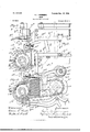
- Fig. Si is an elevation of the change end of the said loom.
- Fig. 4 is a detail view showing chiefly the means of relieving the pressure of the protectonfingers upon the shuttle-binders.
- Fig. 5 is an elevation of the cam for operating the ejector.
- Fig. 6 is a rear elevation of the said loom.
- Fig. 7 is a detail front elevation showing chiefly the means whereby the introduction of a reserve shuttle into the change shuttle-box is guarded against in case the working shuttle fails to complete its return flight to such shuttle-box.
- Fig. S is an end elevation of the parts which are represented in Fig. 7.
- Fig. 9 is an inverted plan view of the parts which are represented in Figs. 7 and 8.
- Fig. lO is a view in vertical section on the plane indicated by the dottedline 10 l0 in Fig. G, showing chiefly parts which are concerned in finding the pick.
- Fig. ll is a detail view of certain of the parts which are shown in Fig. l0, representing them in different positions.
- Fig. l2 is a plan of the parts which are shown in Fig. IO.
- Fig. 13 is a sectional view on about the vertical plane indicated by the dotted line 13 13 in Fig. 2, looking in the direction of the arrows at the ends of such line, showing chiefly the dead-stop.
- Fig. 14 is a plan view of the parts which are represented in Fig. 13. Figs. l5
- FIGS. 13 and 16 are views similar to Figs. 13 and 14, are in practice operatively combinedwith the showing a modified form of dead-stop.
- the drawings show the end frames aa of an ordinary loom, as well as the breast-beam a2 thereof, the front and rear cross-girths a3 and a4, respectively, the crank-shaft a5, the camshaft a6, and the driving gear-wheels a7 and as on the said shafts. They show also the lay-beam a9, the lay-swords au au, and the pitmen or connecting-rods L12 (112 joining the lay with the ,crank-shaft.
- the main power or driving arrangements employed in practice may be of any suitable or approved character.
- I have represented in the drawings fast and loose band-pulleys b b' of usual character mounted on the crankshaft a5, and a common form of shipper mechanism comprising the shipper-handle b2, ⁇ vork ing in a slot in the usual holding-plate b3 at one end of the breast-beam, a spring b4 acting on the shipper-handle with a tendency to move it in a direction to throw off the power, alever b5 operatively connected with the shipper-handle, andthe slide h6, carrying the shipper-fork 297 and engaged by the said lever.
- brake mechanism which in the main is of usual character, it comprising a brake-wheel bs on the crank-shaft, a brakeband b9 almost encircling the said brakewheel and having one end thereof connected with a fixed part, as bw, and the other connected with a brake-levert7 which is acted upon by a spring 512, tending to tighten the brake-band around the brake-wheel; also, the bell-crank Z913, pivotally mounted upon a suitable bracket Z914 and having the rod 515 hung from one arm thereof and passed through a hole in the forward arm of the brake-lever, the said rod having thereon below the brake-lever a stop or collar bw for engagement with the brake-lever, and the other arm of the bell-crank being disposed in the path of movement of the shipper-handle, whereby when the shipper-handle is moved to throw on the power the bell-crank is partially turned and the brake-pressure is relieved, while when the shipper-handle is caused to move
- crank-shaft 0.5 and cam-shaft a6 crank-shaft 0.5 and cam-shaft a6. It will be obvious that the said weaving instrumentalities will either act or stand at rest, according as the driving power is thrown into or out of connection with the said shafts.
- the shipper-handle is thus disengaged automatically herein by movement of the usual knocking-off lever c, the said lever coperating with the slide c of the weft-fork c2 and being actuated in usual manner by the advance of the said slide.
- the said advance is occasioned by engagement with the gooseneck c3 with the tail of the weft-fork in the forward sweep of the upper end of the gooseneck, as the gooseneck is actuated by the cam c, mounted on the cam-shaft a6.
- the weft-fork c2 and its accessories constitute merely one form of instrumentalities by means of which to ascertain the condition of the working weft-supply and indicate the arrival of the proper time for the rest in the working of the weavinginstrumentalities, as well as for the action of the weft-replenishing instrumentalities.
- protector mechanism of usual character, comprising the swells or binders d d of the respective shuttle-boxes on the lay, the protector-fingers d2 d3, coperating therewith, the protector-shaft d4, the spring d5, operating with a tendency to turn the said protector-shaft to press the protectorfingers against the swells or binders and bear the latter inwardly into the shuttle -boXes, the dagger d6, Fig. l, mounted upon the protector-shaft,and the frog C17, movably mounted upon the end frame a of the loom.
- the dagger d6 Fig. l mounted upon the protector-shaft,and the frog C17, movably mounted upon the end frame a of the loom.
- the weft replenishing instrumentalities which are presented herein are of the same type as those which are presented in my patents and application aforesaid. They operate by replacing the spent or failed working shuttle on the lay by a fresh or reserve shuttle. The change of shuttle is effected, preferably, at the end of the loom opposite that at which the driving appliances are located.
- the replenishing instrumentalities comprise in the said patents a device to relieve the ⁇ pressure of the swell or binder upon the shuttle in the shuttle-box at the change end of the loom, a device to open the said shuttle-box by withdrawing the shuttle-box front from its normal position, a device to expel or eject the spent or failed working shuttle from the said shuttle-box, a device to introduce a fresh or reserve shuttle into the said shuttle-box, and a hopper or magazine to contain a reserve supply of shuttles loaded with weft or filling and threaded up for weaving, the various operative parts being under the control of a socalled change-shaft.
- the said instrumentalities are shown herein as follows:
- the rocker which is employed for relieving the pressure of the swell or binder d upon the working shuttle e within the shuttle-box at the change end of the loom is designated f and its bearingf. (See Fig. et.) Itis mounted upon the lay, as heretofore.
- the movable front of the said shuttle-box is designated g, and the rocker with which, ⁇ the said front is connected is designated g', it also being mounted upon the lay, as heretofore.
- the ejector for expelling or ejecting the spent or failed working shuttle from the said shuttlebox after the front g has been withdrawn is designated h, and the rocker with which the same is connected is shown at h', it also being mounted upon the lay, as heretofore.
- the injector for introducing a fresh or reserve shuttle into the said shuttle-box is shown at il, it being carried by an arm pivoted to the loomframe at 1l', as heretofore.
- the hopper or magazine for fresh or reserve shuttles is shown at j, mounted at one end of the breast-beam, as heretofore, the shuttles within the same being designated c.
- the change-shaft is shown at 71;.
- the connections extending from rockers f g' h' and injector i are designated, respectively, f2, g2, h2, and i2, the levers with which the said connections are joined are designated, respectively, f3, g3, h3, and t3, and the cams on change-shaft 7s, which engage with the said levers, are designated, respectively, f4, g4, h4, and f4.
- the sheaves around which connections f2, g2, and h2 pass are designated l.
- the vspring .acting upon rocker g' to return the shuttle-box front g to normal position after the change of shuttles has been effected is designated g5.
- the cam h4, Fig. 5 is constructed to hold the ejector retracted positively at all times except when it is requred to advance in order to effect the expulsion or ejection of the spent or failed working shuttle.
- the advancing movement of the ejector is occasioned by means of a spring 71,5, Fig. 3, connected with rocker h and with the lay-beam, and is permitted by a drop h6, Fig. 5, in the acting portion of cam h4.
- the injector is furnished with fingers t5, which are mounted to turn freely on a rod i, carried by the injector, the depending ends of the said fingers being connected by a rod t7, so that the fingers shall move in unison, and a spring t8 being connected to one of the fingers and operating to hold the engaging ends of the fingers normally in their operative upraised position.
- These lingers are intended to engage with the bottom shuttle in the hopper or magazine in the rearward movement of the injector and to carry said shuttle with the injector.
- the change-shaft operates during the standstill of the weavin g instru mentalities.
- the restarting-arm on the change-shaft is designated m.
- the arm with which it cooperates is shown at m', and the restarting rock-shaft on which the latter arm is mounted is shown at m2, the arm on said rock-shaft which engages with the shipper-handle being designated m3.
- the supplementary driving mechanism by means of which the change-shaft is rotated, is characterized by the employment therein of power connections operating independently of the throwing ou and off of the driving power of the weaving instrumentalities.
- a worm-gear connected with the change-shaft, a worm, a band-pulley, a continuously-operatingdriving-band, and a shipper under control of the weft-indicating instrument-alities.
- the worm-wheel 70 is fast on the chan ge-shaft, and the worm 702, which engages therewith, is on a short shaft 703, standing at right angles to the change-shaft.
- the band-pulley 704 is fast on the shaft 703, a loose band-pulley 705 being placed alongside the same on the said shaft.
- the shipper is constituted in the said embodiment by a shifterfork 706, carried by a slide-bar 707,. mounted in guides 708, in which last the said slide-bar is free to move parallel with shaft 703.
- a prominent characteristic of the driving-band 7011 is the fact that it is independently operating-that is to say, the driving power applied to move the same and the supplementary driving mechanism is not thrown off by the mere act' of throwing on the main driving power of the loom in restarting theweavinginstrumentalities.
- the said driving band 7011 continues to be actuated through denite application of power thereto after the powerhas been thrown onto the weaving instrumentalities,and thereby it eft'ectuates positively the completion of the various movements which the changeshaft, restarting instrumentalities, dac., are required to perform and replaces the parts in condition to operate anew at the required moment under the dictation of the web-indicator devices.
- An arm 7012 is mounted on change-shaft 70 with capacity to swing loosely thereon and provided at its free end with a pin 70121, arranged to engage with collar 7010. (See Fig. 1.)
- the said arm is connected by a rod or link 7013 with an arm 7014 of a rocker 7015, Fig. 6, the latter having a second arm 7016, that is conneoted by a wire or the like 701'7 with a pivoted arm 7018 at the front of the loom.
- the upper end of the arm 7018 is in position to be carried forward by the advance ofthe weft-fork slide c.
- a latch n pivoted to the rear gear a4 and operated by a spring n', engages with an arm n on the rocker 7015 to hold the driving-band 7011 on fast band-pulley 704 until the changeshaft 70 has been rotated to the required extent.
- An arm n3 on the change-shaft effects the disengagement of the latch n from the said arm n2.
- a brake-lever o Figs. 1 and 6, is pivoted loosely at its lower end at o to a suitable fixed support, its brake-shoe being arranged to act when required against the fast bandpulley 704 and its upper end being acted upon by a spring 02.
- An antifriction-roll os is mounted on the said upper end to take bearing against a cam o4, with which the shipper 706 is furnished. As the said shipper is moved to throw on the power to set the change-shaft in motion the said cam presses the brake away from the pulley 704, while when the shipper is moved to throw olf the power the spring o2 is permitted to act to apply the brake to the said pulley, and thereby arrest at once the rotation of the shaft 703.
- Thelocking-disk on the chan ge-shaft is designated p in Fig. 6, the locking-arm coacting therewith being shown at p', the said arm carrying the pin p2, which enters the lockingnotch in the said disk, and being actuated by the spring p3.
- the device which guards against the placing of a reserve shuttle in working position upon the lay in case the shuttle previously at work on the latter has not been expelled or ejected is shown in place in Figs. 2and 3 and in detail in Figs. 7, 8, and 9.
- the said device operates to detain the picker-stick of the change shuttle-box in an intermediate or partly-advanced position in its return after having been operated to throw the shuttle to the opposite end of the loom until the shuttle in completing its next flight back into the change shuttle-box acts to carry the picker-stick back IOO IIO
- picker-sticks are designated q q
- theslot in which the one at the change end of the loom works is designated q in Fig. 9.
- the particular form of picker-stick-detaining device which I have presented herein comprises an arm g2, which is pivoted at Q3 at one side of the said slot q', one end of the said arm having connected therewith the spring Q4, which latter acts with a tendency to draw the said arm across the said slot.
- the free end of the arm is supported by a shelf g5, carried by the lay-beam a9.
- the reserve shuttle which is carried over to the lay by the injector will be prevented from entering fully into the said shuttle-box, because of encountering the picker-stick.
- the loom will then be stopped by the action of the usual protector mechanism in customary manner, except in the event of the spent or failed working shuttle having remained in the ably connected with one of such parts and arranged to encounter the other thereof in order thereby to destroy the momentum of the lay and other going parts of the loom after the driving power has been taken off and the brake applied.
- the bunter is shown in Figs. 13, 14, 15, and 1G as mounted upon the breast-beam a2.
- the bunter r is connected by a pivot r with a stand r2, which is attached to the breast-beam.
- the said pivot r passes through a short slot TX, extendinglengthwise of the bunter.
- the rear end of the bunter extends upward at the rear side of the breast-beam, the front edge of the upwardly-extended portion being parallel with the upright portion of stand r2, which fits against the said side of the breast-beam.
- a spring r connected with the said rear end of the bunter, acts thereon "with a tendency to raise such end.
- a pin r3 projects laterally from the bunter a and bears upon a finger r4, mounted loosely upon a rod or rockshaft ri", located below the breast-beam, and the spring r6 is connected with the finger r4.
- a plate i is applied to a stand or st-ands rcarried by the laybeam, the said plate being backed up by cushioning materialfor example, india-rubber-at r9.
- cushioning material for example, india-rubber-at r9.
- the bunter is held depressed into inoperative position by the action of a slide-bar r11, having a cam-shaped portion. (See Fig. 2.) This bar passes through the guide-slot T21 in stand r2.
- the bunter having been caused to assume its operative position, it is struck by the plate o on the lay in the advance of the lay toward the breast-beam.
- the bunter itself is moved forward on the pivot-pin r', this movement being permitted by slot 'rX in the bunter until the upwardly-extending rear portion of the bunter brings up against the upwardlyextending rear portion of sta-nd r2 or against the rear side of the breast-beam, as the case may be. rested.
- the levers or treadles with which the harness-frames are connected are designated s s in Figs. 2, 6, 10, and 12, the shedding-cams being designated s' s', the usual jack-shaft on which the said cams are mounted being designated s2, and the gearing by means of which the said jack-shaft is driven from the camshaft cts being shown at s3 s4.
- a clutch-sleeve $5 mounted upon the cam-shaft, serving to connect the gear s4 to the latter during the regular working of the loom.
- a clutchlever s6 has the forked end thereof entered into a groove S7 of the clu tch-sleeve,the said clutchlever being acted upon by a spring S8, which tends to hold the clutch-sleeve engaged with the gear.
- the rear arm of the clutch-lever s extends into the range of action of a side cam S9, mounted on change-shaft 7c. In the normal position of the change-shaftm'hile the latter is at rest, a depression of cam S9 allows Then the advance of the lay is ar- ICO IIO
- the shedding-cams have combined therewith devices enabling them to become operatively connected with the change-shaft.
- a sprocket-Wheel s around which passes a sprocket-chain 312, the latter also passing around a sprocket-Wheel 313, which is mounted loosely upon the change-shaft.
- a ratchet- Wheel S14 Connected with sprocket-Wheel S13 is a ratchet- Wheel S14, the latter forming one member of a clutch, by means of Which sprocket-Wheel S13 may be caused to turn in unison with the change-shaft When itis required to transmit motion from the latter to the shedding-cams.
- the other member of the said clutch comprises an arm .915,Whichis keyed to the changeshaft, and a pivoted dog s1, carried by the said arm for engagement with the said ratchet- Wheel S14.
- dog s shall engage ratchet-Wheel S14 and drive the same and sprocket-Wheel S13 during a part of the revolution of change-shaft 7c in order thereby to occasion a shift to a predetermined extent of the shedding-cams s s'. In this manner during the standstill of the weaving instrumentalities the shedding-cams are moved around into the position which will reopen for the reception of the first pick of the fresh weft or.
- a fixed controlling-cam s arranged in the path of the tail of dog S16, acts to hold the dog out of engagement With the ratchet-Wheel S14.
- a cut-away portion of the said cam at 318 releases the dog and permits the latter to engage the ratchet-Wheel to transmit motion to the sheddingcams through the devices described.
- a xed projection, asI S19, herein constituted of a screw for convenience, is then encountered by the tail of the dog, and the latter is disengaged from the ratchet Wheel.
- the tail of the dog passes from the projection s19 to the movable controlling-cam S20, which latter stands normally in the position in which it is shown in Fig. l() and continues to hold the dog out of engagement with the ratchet-Wheel during the remainder of the revolution of the changeshaft.
- the distance from the end of the fixed controlling-cam S17 to the fixed projection S19 is sufficient to enable the dog S16 to remain in engagement with ratchet-Wheel 814 long enough to reverse the shedding-cams tWo steps, which is the extent that is required When the deficiency of weft or filling first presents itself in the flight of the shuttle from the change end of the loom to the driving end thereof, which latter is the end at Which is located the weft-fork c2, which controls the working of the change-shaft.
- the shedding-cams When the deficiency of weft presents itself first in the flight of the shuttle in the reverse direction, the shedding-cams will require t-o be turned back one step farther in order to reopen the right shed, on account of the fact that one additional pick will intervene before the motion of the parts of the loom is arrested by the action of the weft-fork c2.
- the controlling-cam S21 therefore is made movable in order to enable it to be raised or shifted into the position shown in Fig. ll out of the Way of the dog S15.
- the dog renters into engagement with ratchet-Wheel S14 after passing projection S19 and remains in engagement therewith until it is finally raised out of engagement by its contact with the fixed controlling-cam S17.
- the change-shaft comes to rest With the dog still under the influence of the fixed controlling-cam,
- the shifting of the movable controllingcam 821 is effected through the agency of an auxiliary weft-indicator device at the changev end of the loom.
- the vsaid auxiliary weftindicator device com prises in the present instance a second weft-fork t, mounted on a weft-fork slide t', in connection with which latter is employed an arm t2, that is connected by a cord f3 with an arm t4 on a rocker f5, to which the movable controlling-cam is secured.
- the gooseneck cooperating with the weftfork t is designated u, and its operating-cam is shown at u'.
- the movable controlling-cam 82,1 After being raised in the manner aforesaid the movable controlling-cam 82,1 is held upraised by a latch t, which latter is drawn into engagement therewith by a spring e. After the Weaving instrumentalities have been restarted the latch e is disengaged from the movable controlling-cam, thereby permitting the latter to resume its normal position, through the agency of an unlatching-lever 122, that is actuated by an unlatching-tappet v3 on the cam-shaft a6. 5
- the projection 519 is employed in the path of the tail of dog 316 in order to relieve the rear end of the movable controlling-cam S21 from the strain of forcing the engaging end of such dog out of engagement with the teeth of ratchet-Wheel S14. In some cases the said projection may be omitted.
- the employment of the restarting-shaft m2, located in a position extending from front to rear of the loom, enables me to simplify very much, when desired, the arrangements for shipping the driving power on and off.
- the shipper-handle and shipper-fork are in some cases applied directly to the said shaft m2, which dispenses with the necessity for using a number of the parts which are shown in Fig. 1.
- the shipper-fork is applied to shaft m2 at either the front or the rear of the crank-shaft, according as it is desired to belt from above or below, and for convenience in enabling the loom to be belted either from above or below the loose pulley is arranged at the inner side of the fast pulley.
- the supplementary driving mechanism is made adjustable around the axis of the worm-gear 7c', which axis coincides in the present instance with that of the change-shaft 7o.
- the stand 7021 which contains the bearings for shaft 7c3 and the guides 7a2 7a2 for the slide-bar k7 of the shipper, is held to bracket 7r22 on the loomframe by bolts R23 7623, passing through slots 71:24 7524 in the said bracket.
- the said slots are concentric with the axis of the change-shaft.
- the bunter r occupies an elevated position with its acting end interposed between the lay-beam and breast-beam, as in Figs. 13 and 15.
- the bunter is depressed automatically by the cam of the slide-bar 'r11 when the shipper-handle is moved to throw on the driving power. It sometimes is desired to move the lay by hand during a stoppage without throwing on the driving power.
- I provide a manuallyoperable disengaging-lever,by means of which the bunter may be depressed out of the way of the lay.
- One arrangement of the said lelever is shown at r2, its pivot being designated T22.
- This lever is located at any convenient point to act upon the slide-bar r11. Herein it is arranged at right angles to the said slide-bar, above the latter, with its free extremity projecting forward beneath the breast-beam. Pressure exerted upon the said free end by the Weaver will depress both the free end of the slide-bar and the acting end of the bunter.
- I cla-im as my invention- 1.
- the ejector, the cam operating positively to retract the ejector, and means operating with yielding force to advance the ejector to perform its work.
- driving appliances for the weaving instrumentalities weft-indicator devices to arrest the action of the weaving instru mentalities, instru mentalities to replenish the working weft-supply and then restart the regular Working of the loom, and driving mechanism for the latter instrumentalities including independently-operating power connections, a shipper under control of the weft-indicator devices, and means to' unship such independently operating power connections after the restarting of the action of the weaving instrumentalities.
- driving appliances for the weaving instrumentalities weft-indicator devices operating to arrest the action of the Weaving instrumentalities, instrumentalities operating to replenish the Working weft-supply and then restart the regular working of the loom, and driving mechanism for the latter instrumentalities including a continuously-driven independentlyoperating power connection, a shipper under control of the weft-indicator devices, and means to unship such power connections ai"- ter the restarting of the action of the weaving instrumentalities.
- weft-indicator devices weft-replenishing instrumentalities
- driving mechanism therefor including a shipper operated by the weft-indicator devices to throw on the power, a latch to hold the said shipper in driving position, and a latch-disengager to release the shipper after the completion of the replenishing operations.
- weft-indicator devices weft replenishing. instrumentalities
- a change-shaft in operative control of said instrumentalities
- driving mechanism for said change-shaft including a shipper operated from the said weft-indicator devices, a latch to hold the shipper in driving position, and a latch-disengager to release the shipper after the completion of the replenishing operations.
- loom driving appliances in combination, loom-stopping mechanism, weft-indicator devices in operative control of the said mechanism, Weftreplenishing instrumentalities, driving mechanism for said instrumentalities including a shipper operated IZO from said weft-indicator devices, a latch to hold the shipper in driving position, loom-restarting appliances, and a latch-disengager to release the shipper after the completion of the replenishing operations and the restarting of the loom.
- Weftreplenishing instrumentalities including a shipper operated IZO from said weft-indicator devices, a latch to hold the shipper in driving position, loom-restarting appliances, and a latch-disengager to release the shipper after the completion of the replenishing operations and the restarting of the loom.
- weft-indicatordevices weftreplenishing instrumentalities
- a change-shaft in operative control of said instrumentalities
- driving mechanism for said change-shaft comprising a worm-gear, a worm, and power connections for driving said Worm
- a shipper in operative connection with said power connections and also with the weft-indicator devices, whereby when the latter act the power is shipped on for driving the change-shaft a shipper-latch to hold the power on, and a latch-disengager operating to release the shipper when the required revolution of the change-shaft has been effected.
- weft-indicator devices vweft replenishing instrumentalities
- the change-shaft in operative control of the said instrumentalities
- driving mechanism for the change-shaft comprising a worm-gear, worm,
- the lay automatic means to transfer a reserve shuttle thereto, a picker-stick, and means to hold the picker-stick, after its pick, in an intermediate or partly-advanced position adapted to obstruct the movement of the reserve shuttle onto the lay.
- the lay automatic means to transfer a reserve shuttle thereto, a picker-stick, and a detent device to arrest the picker-stick, after its pick, in an intermediate or partly-advanced position, to obstruct the movement of the reserve shuttle onto the lay.
- the lay automatic means to transfer a reserve shuttle thereto, a picker-stick, means to cause the same to stand after its pick in an intermediate or partly-advanced position which will obstruct the movement of the reserve shuttle onto the lay, and protector devices to stop the 55 loom.
- tomatic means to transfer a reserve shuttle thereto, a picker-stick, a detent device to arrest the picker-stick, after its pick, in a partly-advanced position which will obstruct the movement of the reserve shuttle onto the lay, the said detent permitting the blow of the working shuttle to drive the picker-stick into its outermost position out of the path 0f the reserve shuttle, and protector devices to stop the loom.
- weft-indicator devices driving appliances for the weavinginstrumentalities under the operative control of the said devices, the lay, instrumentalities under the control of the weft-indicator devices to replenish the working weft-supply on the lay, and a dead-stop under the operative control of the said weft-indicator devices and acting positively to destroy the momentum of the going parts of the loom.
- weft-indicator devices driving appliances for the weavinginstrumentalities under the operative control of the said devices, the lay, instrumentalities under the control of the weft-indicator devices to replenish the Working weft-supply on the lay, and a movable dead-stop under the control of the weft-indicator devices interposed between the breast-beam and the lay, to destroy the momentum of the lay.
- weft-indicator devices driving appliances for the weaving instrumentalities under the operative control of the said devices, the lay, instrumentalities under the control of the weft-indicator devices'to replenish the Working weft-supply on the lay, the movable dead-stop under the control of the weft-indicator devices to destroy the momentum of the lay, and the cushion to cooperate with the said dead-stop.
- weft-indicator devices to arrest the action of the Weaving instrumentalities, the changeshaft under the operative control of the said devices, weft replenishing and restarting instrumentalities under operative control of the change shaft, the sheddingcams, and pick-finding instrumentalities also under operative control of the change-shaft to shift the shedding-cams into position to reopen the proper shed for reception of the first pick of fresh weft or filling.
- weft-indicator devices detecting for picks of the shuttle in both directions, replenishing instrumentalities operating under the control of the weft-indicator devices to supply fresh weft or illingat one end of the lay, and pick-finding instrumentalities to shift the shed-forming mechanism into position to recover the true shed corresponding with the pick of the shuttle in either direction.
- weft-indicator devices detecting for picks of the shuttle in both directions, replenishing instrumentalities operating under the control of the weft-indicator devices to supply fresh weft or filling at one end of the lay, the sheddingcams, and pick-finding instrumentalities under operative control of the said weft-indicator devices to shift the shedding-cams into position to reopen the true shed corresponding With the pick of the shuttle in either direction.
- weft-indicator devices in combination, weft-indicator devices, the shedding-cams, operating means therefor, and pick-finding instrumentalities under operative control of the said weft-indicator devices to shift -the said shedding-cams into position to reopen the required shed, including a driving-dog and means to control the extent of its driving action in effecting the shift of the said shedding-cams.
- weft-indicator devices weft-indicator devices, the shedding-cams, operating means therefor, and pick-findinginstrumentalities under operative control of the said weft-indicator devices to shift the said shedding-cams into position to reopen the true shed, including a driving-dog and a movable controller therefor in operative connection with the weft-indicator devices to regulate the extent of the shift of the said sheddingcams.
- weft-indicator devices in combination, weft-indicator devices, the shedding-cams, operating means therefor, and pick-finding instrumentalities comprising a shaft, means to rotate the same under control ofthe weft-indicator devices, and connections intermediate the said shaft and shedding-cams to shift the latter, including a driving-dog and a movable controller in operative connection with the weft-indicator devices to regulate the extent of the shift of the shedding-cams.
- driving apopen the true shed including a driving-dog and a movable controller therefor in operative connection With the weft-indicator devices to regulate the extent of the shift of the said shedding-cams.
Description
No. 639,975. Patente-d nec. 26, |899.
H. l. HAnmMAN.
YN: MORRIS Pains co, PHoTuLITo., www-Maron. n. c.
No. 639,975. Patented nec. 2s, |899. H. l. HAHRIMAN.
LOOM. (Application led Aug. 10, 1899.) (No Model.) -8` Sheets-Sheet 2,
N v e m Q Q N um@ 9 l "IH 9 QSO Q O qi. (o 9.5
0U Vn /b's CZO "f7/begs.
No. 639,975. Patented Dc. 26, |899.,
H. l. HARRIMAN.
LOOM.
(Application led Aug. 10, 1899.) (NoModel.) 8 Sheets-,Sheet 3.
e La? a ZUz/'nessea- Z2/vena 7..-
@M 576;@ A Wm ls :TENS C0.. PHDYOLrma., ufAsmNoTuN. o. c
No. 639,975. Patented Dec. 26, |899.
H. HARHIMAN.
LOOM.
(Application led Aug. 10, 1899.! (No Modem" 8 Sheets-Sheet 4.
@www5 @QW Lig-.5%
his @4?20 rneys.
Patented Dec. 26, i899. H. HARRIMAN.
(Application led Aug. 10, 1899.)
(No Model.)
8 Sheets-Sheet 5.
Inl/'e nzor.-
his c/Qorneys.
No. 639,975. Patented Dec. 26, |899. H. l. HARHIMAN.
LDUM.
(Application led Aug. 10, 18499.) (No Model.) 8 Sheets-Sheet 6 No. 639,975. Patented Dec.r26, |899.
H. |'..HAHR|MAN.
LOOM.
(Application filed Aug. 10, 1899.)
(No Model.) 8 Sheets-Sheet 7.
Zzjn 65565.- nven o 7".-
wf. f. M, www; @gw @JQ his @gita/Heya.
N0.5s9,975. Patmued nen 26,1899] H|.HARmMAN.
LNI.A
(Application led Aug. 10, 1899.) (No Model.) 8 Sheets-Sheet B.
LMiki@ Zinesses: In vena 7.-
@M M @Mhmfmmq PATENT union.
HENRY I. IIARRIMAN, OF NE\V YORK, N. Y.
LOOM.
SPECIFICATION forming part of Letters Patent No. 639,97 5, dated December 26, 1899;
Application iilecl August 10, 1899. Serial No. 726,732. (N model.)
To @ZZ-when@ t may concern:
Be it known that I, HENRY I. HARRIMAN, a citizen of the United States, residing at New York, in the county of New York, State of New York, have invented a certain new and useful Improvement in Looms, of which the followingr is a specification, reference being had therein to the accompanying drawings.
The invention has relation to looms of that class in which replenishment of the working weft-supply in a loom-t'. c., the weft or filling that is being incorporated into the web or fabric being woven-is eected automatically when necessity arises for such replenishment by instrumentalities with which the loom is provided. Certain looms of the said class contain automatic instrumentalities which are contrived and' arranged to become operative when the condition of the Working weft-supply in a loom calls for replenishment thereof to occasion a dwell or rest in the working of the' weaving instrumentalities of such loom, replenish the working weft-supply during such dwell or rest, and then cause the said weaving instrumentalities to resume their normal working.
Looms which operate in substantially the particular manner just set forth are presented, for instance, in my United States Letters Patent No. 626,834, granted June 13, 1899, No. 636,228, granted October 31, 1899, and No. 637,113, granted November 14, 1899.
My present invention has relation more especially to looms in which the weaving instrumentalities are brought to a standstill for the performance of the various operations which are incidental to replenishment of the workin g weft-supply. It is to be understood, however, that the invention is not restricted in all respects to looms operating in this precise` manner.
One object of the invention is to improve the means of operating the ejector which is employed in certain looms of the general class afoiesaidMas, for example, in the looms of my patentand applications aforesaid-for the purpose of expelling or ejecting from one of thel shuttle-boxes on the lay the spent or failed working shuttle. Heretofore the said ejector has been held in its normal or retracted position by the action of a spring and has been advanced positively for effecting the sion breakage when the ejector encounters anl obstruction in its advance. In accordance with one portion of the present invention I provide actuating means for the ejector operating to hold the latterpositively and deiinitely in the desired retracted position by the action of a cam and to advance the same with yielding force, as by the action of a spring, in effecting the ejection of a shuttle.
In the loom of my present invention, as in that of my application tiled May 8, 1899, aforesaid, the weft-indicator devices operate to bring the weavlng iustrumentalitiesl to a standstill and simultaneously therewith inaugurato the working of the replcnishing instrumentalities, the weaving instrumentalities being automatically restarted after the replenishment has been completed.
Another object of the present invention is to provide a simple and efcient supplementary driving mechanism for actuating the` parts which are required to operate during the standstill of the weaving instrumentalities.
Another object of the invention is to provide means for guarding against the placing of a reserve shuttle in working position upon the lay by the injector before the shuttle previously at work on the latter has been eX- pelled or ejected.
It happens sometimes that the weft-replenishing instrumentalities are set in operation at a time when the Working shuttle on the lay has failed to return to the place at which the expulsion or ejection thereof is arranged to occur, and consequently such expulsion or ejection does not take place. If now the weft-replenishing instrumentalities are permitted to place a reserve shuttle in working position `upon the lay while the previous Working shuttle still remains there, accidents of a IOO well-known character will result from the presence of the two shuttles upon the lay at one time. In accordance with another portion of the invention, therefore, I provide means whereby the entrance of a reserve shuttle into working position in the shuttle-box at the end of the lay where the supply is effected is prevented from taking place in the regular automatic working of the replenishing instrumentalities in case the spent or failed working shuttle has failed to return to the said shuttle-box and be ejected therefrom. In practice I provide means whereby the picker-stick which coperates with the said shuttle-box is detained in an intermediate or somewhat advanced position in each return movement thereof after having been actuated to throw the working shuttle from the said shuttle-box. The said means is contrived to permit the working shuttle on its return from the opposite end of the loom to drive the picker-stick back into its outermost position, where the picker-stick remains nntil again actuated to eect a pick. In its intermediate or partially-advanced position the picker-stick obstructs the entrance of a reserve shuttle into the shuttle-box and prevents such shuttle from getting into position to be picked through the warps or to hold back the swell or binder.
Another object of the invention is to pro- Vide means for enabling the lay and other working parts of the loom to be positively brought to rest in positions which will facilitate the easy change of shuttles and in restarting will enable the loom to acquire sufficient headway to insure a strong first pick. With the foregoing ends in view I provide a dead-stop, which on coming into engagement after the driving power of the loom has been taken 0H will at once overcome the momentum of the going parts of the loom. Thereby the movement of said parts is almost immediately arrested, the lay being brought to a standstill with at most a slight rebound. The said dead-stop supplements by its action that of the brake, so that in. case the brake fails to arrest the working of the loom before the lay reaches bottom center the deadstop will come into play and further movement of the lay and other going parts will be prevented. The dead-stop comprises usually one or more movable bunters, which are arranged to move into and out of position to arrest the to-and-fro movements of the lay and are operatively combined with the shipper devices, whereby when the latter are moved to throw oif the power the dead-stop is moved into operative position, while when the said devices are moved to throw on the power the dead-stop is rendered inoperative.
Another object of the invention is to provide means for automatically finding the pick-'L'. e., causing a reopening, for the reception of the first pick of the fresh weft or filling supplied by the replenishing devices, of the shed into which weft or filling should be laid in order to prevent break in the weave of the web or fabric being produced. In accordance with this part of the invention I provide instrumentalities whereby the shedding mechanism is shifted to the proper position to reopen the proper shed for the reception of the said first pick of fresh weft when the weaving is resumed. V
Another object of the invention is to pro; vide against the occurrence of accidents in case the change-shaft and replenishing instru men talities should, through mischance or carelessness of the weaver or otherwise, happen to be thrown into action during the regular working of the loom. In accordance with another part of the invention, therefore, as a precaution in case the change-shaft should become started up accidentally during the regular working of the loom, the replenishing instrumentalities are contrived in such manner as to cause the front of the shuttle-box at the change end of the loom to be raised before the pressure transmitted from the protector-spring to the swells or binders is relieved. Vhen, now, the lay beats up with the working' shuttle in the change shuttleboX, the said shuttle will be thrown out. The protector mechanism will be free to act in the next forward beat of the lay to stop the loom before any injury is occasioned.
The accompanying drawings illustrate the best form in which I have thus far practically embodied the invention.
In the drawings, Figure l represent-sin elevation the driving end, of a loom embodying the present invention, the said ligure illustrating only features of the said invention and such of the usual parts of the loom as require to be shown or referred to in order to render clear the nature and relations of the invention. Fig. 2 is a similar front elevation of the said loom. Fig. Sis an elevation of the change end of the said loom. Fig. 4 is a detail view showing chiefly the means of relieving the pressure of the protectonfingers upon the shuttle-binders. Fig. 5 is an elevation of the cam for operating the ejector. Fig. 6 is a rear elevation of the said loom. Fig. 7 is a detail front elevation showing chiefly the means whereby the introduction of a reserve shuttle into the change shuttle-box is guarded against in case the working shuttle fails to complete its return flight to such shuttle-box. Fig. S is an end elevation of the parts which are represented in Fig. 7. Fig. 9 is an inverted plan view of the parts which are represented in Figs. 7 and 8. Fig. lO is a view in vertical section on the plane indicated by the dottedline 10 l0 in Fig. G, showing chiefly parts which are concerned in finding the pick. Fig. ll is a detail view of certain of the parts which are shown in Fig. l0, representing them in different positions. Fig. l2 is a plan of the parts which are shown in Fig. IO. Fig. 13 is a sectional view on about the vertical plane indicated by the dotted line 13 13 in Fig. 2, looking in the direction of the arrows at the ends of such line, showing chiefly the dead-stop. Fig. 14 is a plan view of the parts which are represented in Fig. 13. Figs. l5
IOO
IIO
and 16 are views similar to Figs. 13 and 14, are in practice operatively combinedwith the showing a modified form of dead-stop.
The drawings show the end frames aa of an ordinary loom, as well as the breast-beam a2 thereof, the front and rear cross-girths a3 and a4, respectively, the crank-shaft a5, the camshaft a6, and the driving gear-wheels a7 and as on the said shafts. They show also the lay-beam a9, the lay-swords au au, and the pitmen or connecting-rods L12 (112 joining the lay with the ,crank-shaft.
The main power or driving arrangements employed in practice may be of any suitable or approved character. I have represented in the drawings fast and loose band-pulleys b b' of usual character mounted on the crankshaft a5, and a common form of shipper mechanism comprising the shipper-handle b2,\vork ing in a slot in the usual holding-plate b3 at one end of the breast-beam, a spring b4 acting on the shipper-handle with a tendency to move it in a direction to throw off the power, alever b5 operatively connected with the shipper-handle, andthe slide h6, carrying the shipper-fork 297 and engaged by the said lever. I have shown also brake mechanism which in the main is of usual character, it comprising a brake-wheel bs on the crank-shaft, a brakeband b9 almost encircling the said brakewheel and having one end thereof connected with a fixed part, as bw, and the other connected with a brake-levert7 which is acted upon by a spring 512, tending to tighten the brake-band around the brake-wheel; also, the bell-crank Z913, pivotally mounted upon a suitable bracket Z914 and having the rod 515 hung from one arm thereof and passed through a hole in the forward arm of the brake-lever, the said rod having thereon below the brake-lever a stop or collar bw for engagement with the brake-lever, and the other arm of the bell-crank being disposed in the path of movement of the shipper-handle, whereby when the shipper-handle is moved to throw on the power the bell-crank is partially turned and the brake-pressure is relieved, while when the shipper-handle is caused to move to throw off the powerthe spring Z912 is permitted to apply the brake; also, the hand-operated lever Z917, having hung thereto the rod bis, passing through a hole in the brake-lever Z911 and having thereon below the latter the stop or collar bw, whereby the brake-pressure may be relieved by hand when required.
The features which thus far have been described with reference to the drawings are merely those which are usual in looms and are presented herein simply in order to aid in the disclosure of the invention itself. Any convenient and suitable arrangement and construction ofthe same may be utilized in practice.
It will be understood that the weaving instrumentalities of the loom, the same not needing to be shown or described herein, inasm uch as their character is well understood,
crank-shaft 0.5 and cam-shaft a6. It will be obvious that the said weaving instrumentalities will either act or stand at rest, according as the driving power is thrown into or out of connection with the said shafts.
When the loom is running, it is necessary to unship the driving power from the weaving instrumentalities and apply the brake in order to occasion the desired rest in the working of the weaving instrumentalities during the performance of the operation of replenishing the working weft-supply. This unshipping of the driving power from the weaving instrumentalities is effected in the present instance by shipping the driving-band from fast pulley b to loose pulley b', and this in turn, as well as .the application of the brake, is eifected by disengaging the shipperhandle b2 from its holding-notch in platebg, so as to allow spring b4 to actuate the shipperhandle. The shipper-handle is thus disengaged automatically herein by movement of the usual knocking-off lever c, the said lever coperating with the slide c of the weft-fork c2 and being actuated in usual manner by the advance of the said slide. As will be understood, the said advance is occasioned by engagement with the gooseneck c3 with the tail of the weft-fork in the forward sweep of the upper end of the gooseneck, as the gooseneck is actuated by the cam c, mounted on the cam-shaft a6.
The weft-fork c2 and its accessories constitute merely one form of instrumentalities by means of which to ascertain the condition of the working weft-supply and indicate the arrival of the proper time for the rest in the working of the weavinginstrumentalities, as well as for the action of the weft-replenishing instrumentalities. I do not desire to limit myself in all embodiments of the invention to the use of this particular form or kind of weft-indicator device. The latter is merely the kind that is in most general use. It is operative to ascertain breakage or running out of the working weft-supply. Other forms of devices having the same end in View are known and may be substituted in practice. So, also, in some cases I may employ weft-indicator devices operating whenever the working supply of weft or filling has become exhausted to a predetermined extent.
Devices of this latterkind have been devised heretofore.
I have also shown protector mechanism of usual character, comprising the swells or binders d d of the respective shuttle-boxes on the lay, the protector-fingers d2 d3, coperating therewith, the protector-shaft d4, the spring d5, operating with a tendency to turn the said protector-shaft to press the protectorfingers against the swells or binders and bear the latter inwardly into the shuttle -boXes, the dagger d6, Fig. l, mounted upon the protector-shaft,and the frog C17, movably mounted upon the end frame a of the loom. As usual,
IOO
IIO
in case of failure of the working shuttle to enter a shuttle-box at the end of a iiight across the lay it is intended that the dagger (Z6 shall engage with the frog C27 in the ensuing advance of the lay and force the frog forward to disengage the shipperhandle b2, thereby permitting the unsliipping of the power and occasioning the stopping of the loom.
The weft replenishing instrumentalities which are presented herein are of the same type as those which are presented in my patents and application aforesaid. They operate by replacing the spent or failed working shuttle on the lay by a fresh or reserve shuttle. The change of shuttle is effected, preferably, at the end of the loom opposite that at which the driving appliances are located. The replenishing instrumentalities comprise in the said patents a device to relieve the` pressure of the swell or binder upon the shuttle in the shuttle-box at the change end of the loom, a device to open the said shuttle-box by withdrawing the shuttle-box front from its normal position, a device to expel or eject the spent or failed working shuttle from the said shuttle-box, a device to introduce a fresh or reserve shuttle into the said shuttle-box, and a hopper or magazine to contain a reserve supply of shuttles loaded with weft or filling and threaded up for weaving, the various operative parts being under the control of a socalled change-shaft. The said instrumentalities are shown herein as follows: The rocker which is employed for relieving the pressure of the swell or binder d upon the working shuttle e within the shuttle-box at the change end of the loom is designated f and its bearingf. (See Fig. et.) Itis mounted upon the lay, as heretofore. The movable front of the said shuttle-box is designated g, and the rocker with which,` the said front is connected is designated g', it also being mounted upon the lay, as heretofore. The ejector for expelling or ejecting the spent or failed working shuttle from the said shuttlebox after the front g has been withdrawn is designated h, and the rocker with which the same is connected is shown at h', it also being mounted upon the lay, as heretofore. The injector for introducing a fresh or reserve shuttle into the said shuttle-box is shown at il, it being carried by an arm pivoted to the loomframe at 1l', as heretofore. The hopper or magazine for fresh or reserve shuttles is shown at j, mounted at one end of the breast-beam, as heretofore, the shuttles within the same being designated c. The change-shaft is shown at 71;. The connections extending from rockers f g' h' and injector i are designated, respectively, f2, g2, h2, and i2, the levers with which the said connections are joined are designated, respectively, f3, g3, h3, and t3, and the cams on change-shaft 7s, which engage with the said levers, are designated, respectively, f4, g4, h4, and f4. The sheaves around which connections f2, g2, and h2 pass are designated l. The vspring .acting upon rocker g' to return the shuttle-box front g to normal position after the change of shuttles has been effected is designated g5.
The parts just described operate substan tially as heretofore, more especially as in my said patent, No. 636,228, with the exception of the actuating connections of the shuttle-box front and the ejector. Herein the replenishing instrumentalities are contrived, as hereinbefore noted, to cause the front g of the shutt1ebox at the change end of the loom to be raised before the pressure of the protector-spring is taken off the swells or binder. This result in the working is attained by constructing and arranging the cam g4 so that in its action upon the lever g3, which is connected with the rocker g', carrying the said shuttle-box front g, it shall precede sufficiently the action of cam f4 upon the leverf, connected with the rocker f, which is employed for relieving the protector-pressu re upon the swells or binders d d.
In the case of the actuating connections of the ejector the cam h4, Fig. 5, is constructed to hold the ejector retracted positively at all times except when it is requred to advance in order to effect the expulsion or ejection of the spent or failed working shuttle. The advancing movement of the ejector is occasioned by means of a spring 71,5, Fig. 3, connected with rocker h and with the lay-beam, and is permitted by a drop h6, Fig. 5, in the acting portion of cam h4. As in my said patent, No. 636,228, the injector is furnished with fingers t5, which are mounted to turn freely on a rod i, carried by the injector, the depending ends of the said fingers being connected by a rod t7, so that the fingers shall move in unison, and a spring t8 being connected to one of the fingers and operating to hold the engaging ends of the fingers normally in their operative upraised position. These lingers are intended to engage with the bottom shuttle in the hopper or magazine in the rearward movement of the injector and to carry said shuttle with the injector. They yield in the return movement of the injector on making contact with the shuttle which has dropped to the bottom of the hopper orinagazine, and thereby descend and pass underneath the said shuttle, but rise again in front of the latter in readiness to engage therewith in the next rearward movement of the injector. As in the said patent, No. 636,228, also the injector is furnished with the rearwardly-extending arms if Z9 for the support of the shuttle which is being carriedto the lay by the in j ector, and the connection between the injector and bell-crank 3 includes a spring, as shown, so that the injector having been moved rearwardly by the action of cam t4 the spring may yield as soon as the shuttle carried by the injector is pressed fully home into the shuttle-box. The weight which acts to return the injector to its normal forward position is designated 10.
ICO
IIO
As in my said patent, No. 636,228, the
change-shaft operates during the standstill of the weavin g instru mentalities. The restarting-arm on the change-shaft is designated m. The arm with which it cooperates is shown at m', and the restarting rock-shaft on which the latter arm is mounted is shown at m2, the arm on said rock-shaft which engages with the shipper-handle being designated m3. It will be understood that as the change-shaft completes the required revolution thereof, it being actuated during the said standstill by the supplementary driving mechanism, to which reference will presently be made, the replenishment of the working weft-supply having been effected, the action of the arm m on the arm m' produces a partial revolution of the restarting rock-shaft m2, and this, through the action of arm m3 on the shipperhandle, restores the latter to its notch, thereby throwing off the brake and shipping on the power, restarting the weaving instrumentalities.
The supplementary driving mechanism, by means of which the change-shaft is rotated, is characterized by the employment therein of power connections operating independently of the throwing ou and off of the driving power of the weaving instrumentalities. In the illustrated embodiment thereof it oomprises, essentially, a worm-gear. connected with the change-shaft, a worm, a band-pulley, a continuously-operatingdriving-band, and a shipper under control of the weft-indicating instrument-alities. In the said embodiment of the invention the worm-wheel 70 is fast on the chan ge-shaft, and the worm 702, which engages therewith, is on a short shaft 703, standing at right angles to the change-shaft. The band-pulley 704 is fast on the shaft 703, a loose band-pulley 705 being placed alongside the same on the said shaft. The shipper is constituted in the said embodiment bya shifterfork 706, carried by a slide-bar 707,. mounted in guides 708, in which last the said slide-bar is free to move parallel with shaft 703. lA spring 709 on said slide-bar, compressed between one of said guides and a collar 7010, acts to hold the supplementary driving-band 7011 normally on loose pulley 705. A prominent characteristic of the driving-band 7011 is the fact that it is independently operating-that is to say, the driving power applied to move the same and the supplementary driving mechanism is not thrown off by the mere act' of throwing on the main driving power of the loom in restarting theweavinginstrumentalities. The said driving band 7011 continues to be actuated through denite application of power thereto after the powerhas been thrown onto the weaving instrumentalities,and thereby it eft'ectuates positively the completion of the various movements which the changeshaft, restarting instrumentalities, dac., are required to perform and replaces the parts in condition to operate anew at the required moment under the dictation of the web-indicator devices. 1
An arm 7012 is mounted on change-shaft 70 with capacity to swing loosely thereon and provided at its free end with a pin 70121, arranged to engage with collar 7010. (See Fig. 1.) The said arm is connected by a rod or link 7013 with an arm 7014 of a rocker 7015, Fig. 6, the latter having a second arm 7016, that is conneoted by a wire or the like 701'7 with a pivoted arm 7018 at the front of the loom. The upper end of the arm 7018is in position to be carried forward by the advance ofthe weft-fork slide c. Consequently when the gooseneck o3 engages with the tail of the weft-fork c2 and forces the weft-fork slide c1 forward, operatingthe knocking-off levercand causingthe arrest of the weaving instrumentalities,the arm 7018 is operated also, and thereby the shipper 706 is moved to shift the supplementary driving-band 7011 on to the fast band-pulley 704, setting the change-shaft in motion.
A latch n, pivoted to the rear gear a4 and operated by a spring n', engages with an arm n on the rocker 7015 to hold the driving-band 7011 on fast band-pulley 704 until the changeshaft 70 has been rotated to the required extent. An arm n3 on the change-shaft effects the disengagement of the latch n from the said arm n2.
A brake-lever o, Figs. 1 and 6, is pivoted loosely at its lower end at o to a suitable fixed support, its brake-shoe being arranged to act when required against the fast bandpulley 704 and its upper end being acted upon by a spring 02. An antifriction-roll os is mounted on the said upper end to take bearing against a cam o4, with which the shipper 706 is furnished. As the said shipper is moved to throw on the power to set the change-shaft in motion the said cam presses the brake away from the pulley 704, while when the shipper is moved to throw olf the power the spring o2 is permitted to act to apply the brake to the said pulley, and thereby arrest at once the rotation of the shaft 703.
Thelocking-disk on the chan ge-shaft is designated p in Fig. 6, the locking-arm coacting therewith being shown at p', the said arm carrying the pin p2, which enters the lockingnotch in the said disk, and being actuated by the spring p3.
The device which guards against the placing of a reserve shuttle in working position upon the lay in case the shuttle previously at work on the latter has not been expelled or ejected is shown in place in Figs. 2and 3 and in detail in Figs. 7, 8, and 9. As pointed out at the beginning hereof, the said device operates to detain the picker-stick of the change shuttle-box in an intermediate or partly-advanced position in its return after having been operated to throw the shuttle to the opposite end of the loom until the shuttle in completing its next flight back into the change shuttle-box acts to carry the picker-stick back IOO IIO
intoitsoutermostposition. The picker-sticks are designated q q, and theslot in which the one at the change end of the loom works is designated q in Fig. 9. The particular form of picker-stick-detaining device which I have presented herein comprises an arm g2, which is pivoted at Q3 at one side of the said slot q', one end of the said arm having connected therewith the spring Q4, which latter acts with a tendency to draw the said arm across the said slot. The free end of the arm is supported by a shelf g5, carried by the lay-beam a9. The picker-stick q having been driven inward to propel the shuttle from the change end of the loom, as the said picker-stick swings outward again it makes contact with the edge of the spring-actuated deten t-arm q2. By the action of the said detent-arrn the picker-stick is arrested in about the position that is represented in dotted lines in Fig. 7. rlhe return of the shuttle drives the picker-stick into the position which is represented by full lines in Fig. 7, the blow communicated by the shuttle to the picker-stick being sufficient to overcome the resistance that is offered by the detent-arm. Should the picker-stick remain in the dotted-line position of Fig; 7. at a time when the replenishing devices are set in action in consequence of the spent or failed working shuttle not having returned to the shuttle-box at the change end of the loom, the reserve shuttle which is carried over to the lay by the injector will be prevented from entering fully into the said shuttle-box, because of encountering the picker-stick. The loom will then be stopped by the action of the usual protector mechanism in customary manner, except in the event of the spent or failed working shuttle having remained in the ably connected with one of such parts and arranged to encounter the other thereof in order thereby to destroy the momentum of the lay and other going parts of the loom after the driving power has been taken off and the brake applied. Herein the bunter is shown in Figs. 13, 14, 15, and 1G as mounted upon the breast-beam a2. The bunter r is connected by a pivot r with a stand r2, which is attached to the breast-beam. The said pivot r passes through a short slot TX, extendinglengthwise of the bunter. The rear end of the bunter extends upward at the rear side of the breast-beam, the front edge of the upwardly-extended portion being parallel with the upright portion of stand r2, which fits against the said side of the breast-beam. A spring r, connected with the said rear end of the bunter, acts thereon "with a tendency to raise such end. In the modification which is shown in Figs. 15 and 16 a pin r3 projects laterally from the bunter a and bears upon a finger r4, mounted loosely upon a rod or rockshaft ri", located below the breast-beam, and the spring r6 is connected with the finger r4. For contact with the bunter a plate i is applied to a stand or st-ands rcarried by the laybeam, the said plate being backed up by cushioning materialfor example, india-rubber-at r9. Normally during the regular ru nning of the loom the bunter is held depressed into inoperative position by the action of a slide-bar r11, having a cam-shaped portion. (See Fig. 2.) This bar passes through the guide-slot T21 in stand r2. (See Fig. 15.) Itis arranged to act against the upper edge of the bunter r in Figs. 13 and 14 and is -connected with the shipper-handle b2, as shown in said figures. In Figs. l5 and 16 the slide-bar acts against finger r4. Vhen the shipper-handle is in the position it occupies while the loom is running, the cam of the slide-bar?"11 is held in position to cause the bunter to remain out of action. When, however, the shipper-handle b2 is moved to throw off the main driving power, the movement of the slide-bar r11 in unison therewith allows the spring 0' to act to raise the bunter'into operative position. The bunter having been caused to assume its operative position, it is struck by the plate o on the lay in the advance of the lay toward the breast-beam. The bunter itself is moved forward on the pivot-pin r', this movement being permitted by slot 'rX in the bunter until the upwardly-extending rear portion of the bunter brings up against the upwardlyextending rear portion of sta-nd r2 or against the rear side of the breast-beam, as the case may be. rested.
The levers or treadles with which the harness-frames are connected are designated s s in Figs. 2, 6, 10, and 12, the shedding-cams being designated s' s', the usual jack-shaft on which the said cams are mounted being designated s2, and the gearing by means of which the said jack-shaft is driven from the camshaft cts being shown at s3 s4. It is required that the shedding-cams should be enabled to turn independently of the cam-shaft in iinding the pick in accordance with the illustrated embodiment of the present invention, and therefore the gear s4 is mounted loosely upon the cam-shaft, a clutch-sleeve $5, mounted upon the cam-shaft, serving to connect the gear s4 to the latter during the regular working of the loom. .For moving the clutch-sleeve S5 into and out of engagement'with gear s4 a clutchlever s6 has the forked end thereof entered into a groove S7 of the clu tch-sleeve,the said clutchlever being acted upon by a spring S8, which tends to hold the clutch-sleeve engaged with the gear. The rear arm of the clutch-lever s extends into the range of action of a side cam S9, mounted on change-shaft 7c. In the normal position of the change-shaftm'hile the latter is at rest, a depression of cam S9 allows Then the advance of the lay is ar- ICO IIO
rgo
clutch-sleeve S to remain in engagement With gear s4, and consequently the j ack-shaft s2 derives motion from the cam-shaft. After the change-shaft has been set in motion, however, the acting face o f the cam operates to turn the clutch-lever upon its fulcrnm at 361, thereby disengaging clutch-sleeve S5 from gear s4 and rendering jack-shaft s2 free to move independently of the cam-shaft.
For the purpose of finding the pick while the Weaving instrumentalities otherwise are at a standstill and While the weft-replenishing instrumentalities are engaged in effecting a change of shuttles the shedding-cams have combined therewith devices enabling them to become operatively connected with the change-shaft. Thus on the jack-shaft s2 is made fast a sprocket-Wheel s, around which passes a sprocket-chain 312, the latter also passing around a sprocket-Wheel 313, which is mounted loosely upon the change-shaft. Connected with sprocket-Wheel S13 is a ratchet- Wheel S14, the latter forming one member of a clutch, by means of Which sprocket-Wheel S13 may be caused to turn in unison with the change-shaft When itis required to transmit motion from the latter to the shedding-cams. The other member of the said clutch comprises an arm .915,Whichis keyed to the changeshaft, and a pivoted dog s1, carried by the said arm for engagement with the said ratchet- Wheel S14. It is intended that dog s shall engage ratchet-Wheel S14 and drive the same and sprocket-Wheel S13 during a part of the revolution of change-shaft 7c in order thereby to occasion a shift to a predetermined extent of the shedding-cams s s'. In this manner during the standstill of the weaving instrumentalities the shedding-cams are moved around into the position which will reopen for the reception of the first pick of the fresh weft or.
filling the shed which is deficient in its supply of weft or filling.
During the first part of the revolution of the change-shaft a fixed controlling-cam s, arranged in the path of the tail of dog S16, acts to hold the dog out of engagement With the ratchet-Wheel S14. A cut-away portion of the said cam at 318 releases the dog and permits the latter to engage the ratchet-Wheel to transmit motion to the sheddingcams through the devices described. A xed projection, asI S19, herein constituted of a screw for convenience, is then encountered by the tail of the dog, and the latter is disengaged from the ratchet Wheel. In the ordinary Working of the devices the tail of the dog passes from the projection s19 to the movable controlling-cam S20, which latter stands normally in the position in which it is shown in Fig. l() and continues to hold the dog out of engagement with the ratchet-Wheel during the remainder of the revolution of the changeshaft. The distance from the end of the fixed controlling-cam S17 to the fixed projection S19 is sufficient to enable the dog S16 to remain in engagement with ratchet-Wheel 814 long enough to reverse the shedding-cams tWo steps, which is the extent that is required When the deficiency of weft or filling first presents itself in the flight of the shuttle from the change end of the loom to the driving end thereof, which latter is the end at Which is located the weft-fork c2, which controls the working of the change-shaft. When the deficiency of weft presents itself first in the flight of the shuttle in the reverse direction, the shedding-cams will require t-o be turned back one step farther in order to reopen the right shed, on account of the fact that one additional pick will intervene before the motion of the parts of the loom is arrested by the action of the weft-fork c2. The controlling-cam S21 therefore is made movable in order to enable it to be raised or shifted into the position shown in Fig. ll out of the Way of the dog S15. When this is done, the dog renters into engagement with ratchet-Wheel S14 after passing projection S19 and remains in engagement therewith until it is finally raised out of engagement by its contact with the fixed controlling-cam S17. The change-shaft comes to rest With the dog still under the influence of the fixed controlling-cam,
The shifting of the movable controllingcam 821 is effected through the agency of an auxiliary weft-indicator device at the changev end of the loom. The vsaid auxiliary weftindicator device com prises in the present instance a second weft-fork t, mounted on a weft-fork slide t', in connection with which latter is employed an arm t2, that is connected by a cord f3 with an arm t4 on a rocker f5, to which the movable controlling-cam is secured. The gooseneck cooperating with the weftfork t is designated u, and its operating-cam is shown at u'. When gooseneck u engages with the tail of Weft-fork in the event of failure of weft or filling in the flight of the shuttle toward the change end of the loom and pushes forward weft-fork slide t, it bears forward the arm t2, which latter, through connection t3, turns the rocker t5, thereby raising movable controlling-cam S21 out of the range of the tail of dog S16. (See Fig. 11.) This enables the said dog to rengage the ratchet- Wheel 314 after passing projection S19, as aforesaid. After being raised in the manner aforesaid the movable controlling- cam 82,1 is held upraised by a latch t, which latter is drawn into engagement therewith by a spring e. After the Weaving instrumentalities have been restarted the latch e is disengaged from the movable controlling-cam, thereby permitting the latter to resume its normal position, through the agency of an unlatching-lever 122, that is actuated by an unlatching-tappet v3 on the cam-shaft a6. 5
A screw-threaded post c4, pivoted to the tail of the latch fu, passes through a hole in the rear end of the unlatching-lever v2, and an adjustable nut c5 on said post constitutes a IOO ITO
stop that is engaged by the said lever to disengage the latch from the movable controlling-cam S21.
The projection 519 is employed in the path of the tail of dog 316 in order to relieve the rear end of the movable controlling-cam S21 from the strain of forcing the engaging end of such dog out of engagement with the teeth of ratchet-Wheel S14. In some cases the said projection may be omitted.
The employment of the restarting-shaft m2, located in a position extending from front to rear of the loom, enables me to simplify very much, when desired, the arrangements for shipping the driving power on and off. Thus the shipper-handle and shipper-fork are in some cases applied directly to the said shaft m2, which dispenses with the necessity for using a number of the parts which are shown in Fig. 1. In these cases the shipper-fork is applied to shaft m2 at either the front or the rear of the crank-shaft, according as it is desired to belt from above or below, and for convenience in enabling the loom to be belted either from above or below the loose pulley is arranged at the inner side of the fast pulley.
In order to suit the position of the loom with relation to that of the overhead shaft from which the supplementary driving-band 71:11 is operated, the supplementary driving mechanism is made adjustable around the axis of the worm-gear 7c', which axis coincides in the present instance with that of the change-shaft 7o. To this end the stand 7021, which contains the bearings for shaft 7c3 and the guides 7a2 7a2 for the slide-bar k7 of the shipper, is held to bracket 7r22 on the loomframe by bolts R23 7623, passing through slots 71:24 7524 in the said bracket. The said slots are concentric with the axis of the change-shaft.
During the stoppage of the loom, which is occasioned by unshipping the driving power and applying the brake, the bunter r occupies an elevated position with its acting end interposed between the lay-beam and breast-beam, as in Figs. 13 and 15. The bunter is depressed automatically by the cam of the slide-bar 'r11 when the shipper-handle is moved to throw on the driving power. It sometimes is desired to move the lay by hand during a stoppage without throwing on the driving power. In order to permit this, I provide a manuallyoperable disengaging-lever,by means of which the bunter may be depressed out of the way of the lay. One arrangement of the said lelever is shown at r2, its pivot being designated T22. This lever is located at any convenient point to act upon the slide-bar r11. Herein it is arranged at right angles to the said slide-bar, above the latter, with its free extremity projecting forward beneath the breast-beam. Pressure exerted upon the said free end by the Weaver will depress both the free end of the slide-bar and the acting end of the bunter.
Except as otherwise indicated by limitations embodied in the claims I do not limit myself to the precise arrangement of pick-iinding instru mentalities shown and described herein or to the use thereof in the precise relations shown and described.
I cla-im as my invention- 1. In automatic weft-replenishing mechanism for looms, in combination, the ejector, the cam operating positively to retract the ejector, and means operating with yielding force to advance the ejector to perform its work.
2. In automatic Weft-replenishing mechanism for looms, in combination, the ejector, the change-shaft, the cam thereon operating positively to retract the ejector, and the spring operating to advance the ejector to perform its work.
3. In a loom, in combination, driving appliances for the weaving instrumentalities, weft-indicator devices to arrest the action of the weaving instru mentalities, instru mentalities to replenish the working weft-supply and then restart the regular Working of the loom, and driving mechanism for the latter instrumentalities including independently-operating power connections, a shipper under control of the weft-indicator devices, and means to' unship such independently operating power connections after the restarting of the action of the weaving instrumentalities.
4. In a loom, in combination, driving appliances for the weaving instrumentalities, weft-indicator devices operating to arrest the action of the Weaving instrumentalities, instrumentalities operating to replenish the Working weft-supply and then restart the regular working of the loom, and driving mechanism for the latter instrumentalities including a continuously-driven independentlyoperating power connection, a shipper under control of the weft-indicator devices, and means to unship such power connections ai"- ter the restarting of the action of the weaving instrumentalities.
5. In combination, weft-indicator devices, weft-replenishing instrumentalities, driving mechanism therefor including a shipper operated by the weft-indicator devices to throw on the power, a latch to hold the said shipper in driving position, and a latch-disengager to release the shipper after the completion of the replenishing operations.
G. In combination, weft-indicator devices, weft replenishing. instrumentalities, a change-shaft in operative control of said instrumentalities, driving mechanism for said change-shaft including a shipper operated from the said weft-indicator devices, a latch to hold the shipper in driving position, and a latch-disengager to release the shipper after the completion of the replenishing operations.
7. In combination, loom driving appliances, loom-stopping mechanism, weft-indicator devices in operative control of the said mechanism, Weftreplenishing instrumentalities, driving mechanism for said instrumentalities including a shipper operated IZO from said weft-indicator devices, a latch to hold the shipper in driving position, loom-restarting appliances, and a latch-disengager to release the shipper after the completion of the replenishing operations and the restarting of the loom.
8. In an automatic weft-replenishingloom, in combination, weft-indicatordevices, weftreplenishing instrumentalities,a change-shaft in operative control of said instrumentalities, driving mechanism for said change-shaft comprising a worm-gear, a worm, and power connections for driving said Worm, a shipper in operative connection with said power connections and also with the weft-indicator devices, whereby when the latter act the power is shipped on for driving the change-shaft a shipper-latch to hold the power on, and a latch-disengager operating to release the shipper when the required revolution of the change-shaft has been effected.
r9. In combination, weft-indicator devices, vweft replenishing instrumentalities, the change-shaft in operative control of the said instrumentalities, driving mechanism for the change-shaft comprising a worm-gear, worm,
pulley, and driving-band, the shipper, the
rocker in operative connection with the shipper and the weft-indicator devices, the shipper-latch, and the latch-disengager operating to release the shipping appliances when the required revolution of the change-shaft has been effected. v
10. In a loom, in combination, the lay, automatic means to transfer a reserve shuttle thereto, a picker-stick, and means to hold the picker-stick, after its pick, in an intermediate or partly-advanced position adapted to obstruct the movement of the reserve shuttle onto the lay.
11. In a loom, in combination, the lay, automatic means to transfer a reserve shuttle thereto, a picker-stick, and a detent device to arrest the picker-stick, after its pick, in an intermediate or partly-advanced position, to obstruct the movement of the reserve shuttle onto the lay.
12. In a loom, in combination, the lay, automatic means to transfer a reserve shuttle thereto, a picker-stick, means to cause the same to stand after its pick in an intermediate or partly-advanced position which will obstruct the movement of the reserve shuttle onto the lay, and protector devices to stop the 55 loom.
13. In a loom, in combination, the lay, automatic means to transfer a reserve shuttle thereto, a picker-stick, and a yielding detentV device to arrest the picker-stick, after its Vdetent permitting the blow of the working shuttle to drive the picker-stick into its outermostposition out of the path of the reserve shuttle. y Y
14. In a loom, in combination, the lay, au-
tomatic means to transfer a reserve shuttle thereto, a picker-stick, a detent device to arrest the picker-stick, after its pick, in a partly-advanced position which will obstruct the movement of the reserve shuttle onto the lay, the said detent permitting the blow of the working shuttle to drive the picker-stick into its outermost position out of the path 0f the reserve shuttle, and protector devices to stop the loom.
15. In a loom, in combination, weft-indicator devices, driving appliances for the weavinginstrumentalities under the operative control of the said devices, the lay, instrumentalities under the control of the weft-indicator devices to replenish the working weft-supply on the lay, and a dead-stop under the operative control of the said weft-indicator devices and acting positively to destroy the momentum of the going parts of the loom.
16. In a loom, in combination, weft-indicator devices, driving appliances for the weavinginstrumentalities under the operative control of the said devices, the lay, instrumentalities under the control of the weft-indicator devices to replenish the Working weft-supply on the lay, and a movable dead-stop under the control of the weft-indicator devices interposed between the breast-beam and the lay, to destroy the momentum of the lay.
17. In a loom, in combination, weft-indicator devices, driving appliances for the weaving instrumentalities under the operative control of the said devices, the lay, instrumentalities under the control of the weft-indicator devices'to replenish the Working weft-supply on the lay, the movable dead-stop under the control of the weft-indicator devices to destroy the momentum of the lay, and the cushion to cooperate with the said dead-stop.
18. In a loom, in combination, the lay, the breast-beam, the movable dead-stop,the camshaped slidebar,and the shipper whereby the said slide-bar is actuated.
19. In a loom, in combination, the lay, its shuttle-box, a swell or binder,protector mechanism, and weft-replenishing instrumentalities acting first to open the shuttle-box, and then to relieve the swell or binder of pressure and eect a change of shuttles.
20. In a loom, in combination, the lay, a movable shuttle-box front, a swell or binder, protector mechanism coacting with the said swell or binder, and weft-replenishing instrumentalities acting first to withdraw the said IOO IIO
shuttle-box front and then to relieve the presshuttle-box front taking lead of the others in its action.
22. In a loom, in combination,weft-indicating devices detecting for picks of the shuttle in both directions, a holder for a reserve supply of weft at one end of the lay only,instru lnentalities operatin g under the control of the said weft-indicating devices to introduce or feed fresh weft at the said end of thelayonly, and pick-finding iustrumentalities governed by the said weft-indicating devices and operating to recover the true shed corresponding with the first deficient pick in each direction.
23. In a loom, in combination, weft-indicator devices, the change-shaftunder operative control of the said devices, instrumentalities under operative control of the said changeshaft to replenish the working weft-supply, the shedding mechanism, and pick-finding instrumentalities under operative control of the change-shaft to shift the shedding mechanism into position to reopen the required shed.
24. In a loom, in combination, weft-indicator devices, the change-shaft under operative control of the said devices, instrumentalities under operative control of the said changeshaft to replenish the Working weft-supply, the shedding-cams, operating mechanism for the shedding-cams, and pick-finding instrumentalities under operative control of the change-shaft to turn the shedding-cams to shift them into position to reopen the required shed.
25. In a loom, in combination, driving appliances for the weaving instrumentalities, weft-indicator devices to arrest the action of the Weaving instrumentalities, instrumentalities under the operative control of the said devices to replenish the Working weft-supply and then restart the Weaving instrumentalities, and pick-finding instrumentalities to cause the iirst pick of fresh weft or filling to be received in the proper shed.
26. In a loom, in combination, driving appliances for the Weaving instrumentalities, weft-indicator devices to arrest the action of the Weaving instrumentalities, instrumentalities under the operative control of the said devices to replenish the Working weft-supply and then restart the Weaving instrumentalities, shed-forming mechanism, and pick-finding instrumentalities to shift the shed-forming mechanism into position to reopen the proper shed for the reception of the first pick of fresh weft or filling.
27. In a loom, in combination, driving appliances for the Weaving instrumentalities, weft-indicator devices to arrest the action of the Weaving instrumentalities, instrumentalities under the operative control of the said devices to replenish the Working weft-supply and then restart the Weaving instrumentalities, the shedding-cams and pick-nding instrumentalities also under the control of such devices to shift the shedding-cams into position to reopen the proper shed for reception of the first pick of fresh weft or lling.
2S. In a loom, in combination, driving appliances for the weaving instrumentalities, weft-indicator devices to arrest the action of the Weaving instrumentalities, the changeshaft under the operative control of the said devices, Weft-replenishing and restarting iustrumen talities under operative control of the change-shaft, and pick-finding instrumentalities also under operative control of the change-shaft to reopen the proper shed for the reception of the first pick of fresh weft or filling.
29. In a loom, in combination, driving appliances for the Weaving instrumentalities,
weft-indicator devices to arrest the action of the Weaving instrumentalities, the changeshaft under the operative control of the said devices, weft replenishing and restarting instrumentalities under operative control of the change shaft, the sheddingcams, and pick-finding instrumentalities also under operative control of the change-shaft to shift the shedding-cams into position to reopen the proper shed for reception of the first pick of fresh weft or filling.
30. In a loom, in combination, the shedding-cams, their clutch, the change-shaft in operative control of the said clutch, and instrumentalities under the operative control of the change-shaft to shift the said shedding-cams to find the pick.
3l. In a loom, in combination, weft-indicator devices detecting for picks of the shuttle in both directions, replenishing instrumentalities operating under the control of the weft-indicator devices to supply fresh weft or illingat one end of the lay, and pick-finding instrumentalities to shift the shed-forming mechanism into position to recover the true shed corresponding with the pick of the shuttle in either direction.
32. In a loom, in combination, weft-indicator devices detecting for picks of the shuttle in both directions, replenishing instrumentalities operating under the control of the weft-indicator devices to supply fresh weft or filling at one end of the lay, the sheddingcams, and pick-finding instrumentalities under operative control of the said weft-indicator devices to shift the shedding-cams into position to reopen the true shed corresponding With the pick of the shuttle in either direction.
33. In a loom, in combination, driving appliances for the weaving instrumentalities, weft-indicator devices operating to arrest the action of the Weaving instrumentalities, instrumentalities under the operative control of the said devices to replenish the Working weft-supply and then restart the Weaving instrumentalities,the shedding-cams, and picknding instrumentalities under operative control of the said weft-indicator devices to shift the shedding-cams into position to reioo IIO
open the true shed corresponding with the pick of the shuttle in either direction.
34. In aloom, in combination, weft-indicator devices, the shedding-cams, operating means therefor, and pick-finding instrumentalities under operative control of the said weft-indicator devices to shift -the said shedding-cams into position to reopen the required shed, including a driving-dog and means to control the extent of its driving action in effecting the shift of the said shedding-cams.
35. In a loom, in combination, weft-indicator devices, the shedding-cams, operating means therefor, and pick-findinginstrumentalities under operative control of the said weft-indicator devices to shift the said shedding-cams into position to reopen the true shed, including a driving-dog and a movable controller therefor in operative connection with the weft-indicator devices to regulate the extent of the shift of the said sheddingcams. l
36. Ina loom, in combination, weft-indicator devices, the shedding-cams, operating means therefor, and pick-finding instrumentalities comprising a shaft, means to rotate the same under control ofthe weft-indicator devices, and connections intermediate the said shaft and shedding-cams to shift the latter, including a driving-dog and a movable controller in operative connection with the weft-indicator devices to regulate the extent of the shift of the shedding-cams.
37. In a loom, in combination,Weft-indica tor devices, the shedding-cams, operating means therefor, and pick-finding instrumentalities under operative control of the weftindicator devices to shift the shedding-cams into position to reopen the true shed, including a driving-dog, a movable controller therefor in operative connection with the weft-indicator devices to regulate the extent of the shift of the shedding-cams, a latch for said controller, and means to free the latch.
3S. In a loom, in combination, driving apopen the true shed, including a driving-dog and a movable controller therefor in operative connection With the weft-indicator devices to regulate the extent of the shift of the said shedding-cams.
39. In a loom, in combination, driving appliances for the Weaving instrumentalities, weft-indicator devices operating to arrest the action of the Weaving instrumentalities, the change-shaft under operative control of the said devices, instrumentalities under the operative control of the said change-shaft to replenish the Working weft-supply and then restart the Weaving instru mentalities, the shedding-cams, and pick-iindin g instrumentalities under operative control of the change-shaft to shift the said shedding-cams into position to reopen the true shed, including a drivingdog and a movable controller therefor in operative connection with the weft-indicator devices to regulate the extent of the shift of the shedding-cams.
40. In a loom, in combination, the lay, the breast-beam, the movable dead-stop,the slidebar provided Witha cam to operate the deadstop, the shipper whereby the said slide-bar is actuated, and the manually-operable lever for moving the dead-stop out of the path of the lay.
In testimony whereof I affix my signature in presence of two Witnesses.
HENRY I. lHARRIMAN.
Witnesses:
CEAS. F. RANDALL, WILLIAM A. COPELAND.
Priority Applications (1)
| Application Number | Priority Date | Filing Date | Title |
|---|---|---|---|
| US72673299A US639975A (en) | 1899-08-10 | 1899-08-10 | Loom. |
Applications Claiming Priority (1)
| Application Number | Priority Date | Filing Date | Title |
|---|---|---|---|
| US72673299A US639975A (en) | 1899-08-10 | 1899-08-10 | Loom. |
Publications (1)
| Publication Number | Publication Date |
|---|---|
| US639975A true US639975A (en) | 1899-12-26 |
Family
ID=2708561
Family Applications (1)
| Application Number | Title | Priority Date | Filing Date |
|---|---|---|---|
| US72673299A Expired - Lifetime US639975A (en) | 1899-08-10 | 1899-08-10 | Loom. |
Country Status (1)
| Country | Link |
|---|---|
| US (1) | US639975A (en) |
Cited By (1)
| Publication number | Priority date | Publication date | Assignee | Title |
|---|---|---|---|---|
| US20100125099A1 (en) * | 2006-04-20 | 2010-05-20 | T Hoen Peter Abraham Christiaan | Therapeutic intervention in a genetic disease in an individual by modifying expression of an aberrantly or abnormally expressed gene |
-
1899
- 1899-08-10 US US72673299A patent/US639975A/en not_active Expired - Lifetime
Cited By (1)
| Publication number | Priority date | Publication date | Assignee | Title |
|---|---|---|---|---|
| US20100125099A1 (en) * | 2006-04-20 | 2010-05-20 | T Hoen Peter Abraham Christiaan | Therapeutic intervention in a genetic disease in an individual by modifying expression of an aberrantly or abnormally expressed gene |
Similar Documents
| Publication | Publication Date | Title |
|---|---|---|
| US639975A (en) | Loom. | |
| US652224A (en) | Loom. | |
| US891618A (en) | Stop-motion and reversing mechanism of looms. | |
| US945722A (en) | Pick-finder device for looms. | |
| US1081384A (en) | Loom for weaving bags, &c. | |
| US386506A (en) | thomas | |
| US913969A (en) | Take-up mechanism for looms. | |
| US829689A (en) | Let-off mechanism for looms. | |
| US731622A (en) | Means for preventing warp breakage in looms. | |
| US652105A (en) | Loom. | |
| US740362A (en) | Loom-shuttle-operating mechanism. | |
| US646904A (en) | Loom. | |
| US1021151A (en) | Pick-finder device for looms. | |
| US745078A (en) | Weft-replenishing mechanism for looms. | |
| US390339A (en) | brooks | |
| US371299A (en) | beooks | |
| US646905A (en) | Loom. | |
| US631245A (en) | Weft parting or cutting mechanism for looms. | |
| US454805A (en) | northrop | |
| US787497A (en) | Weft-replenishing mechanism for looms. | |
| US1156007A (en) | Pick finder mechanism employed in looms for weaving. | |
| US731274A (en) | Loom. | |
| US455175A (en) | Setts | |
| US636228A (en) | Loom. | |
| US767426A (en) | Weft-replenishing mechanism for looms. |