US6389864B1 - Heavy duty sheet bending brake - Google Patents
Heavy duty sheet bending brake Download PDFInfo
- Publication number
- US6389864B1 US6389864B1 US09/498,281 US49828100A US6389864B1 US 6389864 B1 US6389864 B1 US 6389864B1 US 49828100 A US49828100 A US 49828100A US 6389864 B1 US6389864 B1 US 6389864B1
- Authority
- US
- United States
- Prior art keywords
- bending
- brake
- sheet
- leg
- assembly
- Prior art date
- Legal status (The legal status is an assumption and is not a legal conclusion. Google has not performed a legal analysis and makes no representation as to the accuracy of the status listed.)
- Expired - Fee Related
Links
Images


Classifications
-
- B—PERFORMING OPERATIONS; TRANSPORTING
- B21—MECHANICAL METAL-WORKING WITHOUT ESSENTIALLY REMOVING MATERIAL; PUNCHING METAL
- B21D—WORKING OR PROCESSING OF SHEET METAL OR METAL TUBES, RODS OR PROFILES WITHOUT ESSENTIALLY REMOVING MATERIAL; PUNCHING METAL
- B21D5/00—Bending sheet metal along straight lines, e.g. to form simple curves
- B21D5/04—Bending sheet metal along straight lines, e.g. to form simple curves on brakes making use of clamping means on one side of the work
- B21D5/042—With a rotational movement of the bending blade
Definitions
- This invention relates to sheet bending brakes.
- Such brakes comprise a fixed member on which the sheet is clamped and a movable bending member for bending the sheet.
- a major problem with respect to such sheet bending brakes is the tendency of the bending member to move relative to the portion of the sheet being bent and thereby mar the surface of the sheet.
- U.S. Pat. Nos. 3,481,174 and 3,482,427 were directed to an arrangement which included a floatable compensator on the bending member which engages the sheet material and as the bending member is swung to bend the sheet pivots so that the contact with the sheet material is maintained.
- a sheet bending brake and stabilizing assembly wherein the sheet bending brake alone is constructed and arranged such that when a workpiece is clamped for bending when a person stands on the floor facing the handle means and the handle means is grasped and raised in a direction away from the person in order to move the handle means and raise the handle means, forces occur which prevent the handle means from moving sufficiently to produce a predetermined bend and the forces cause the entire sheet bending brake to tip away from the person about the portions of the legs which project outwardly from the bending brake and thus prevent the movement of the bending member relative to the first member and prevent bending of the workpiece.
- the stabilizing assembly for counteracting such forces on the sheet bending brake comprises transversely spaced rails receiving at least a portion of the ends of the leg assemblies.
- the transversely spaced rails which receive at least a portion of the leg assemblies have portions extend outwardly from beneath the sheet bending brake beyond the brake toward the side of the brake from which the handle member and handle means are accessible.
- Longitudinally extending rail means interconnecting the transverse rails. The longitudinally extending rail is attached to the portions.
- the weight and positioning of the sheet bending brake, leg assemblies and rail are such that a person standing on the floor and facing the side of the brake, grasping and raising the handle means, forces opposing bending are not counteracted and the bending can not be achieved and such that the person must place one foot or both feet on the longitudinally extending rail means during the movement of the bending member away from the person for performing the bending to a desired bend without tipping of the bending brake away from the person and permit movement of the bending member relative to the first member to bend the workpiece.
- FIG. 1 is a perspective view of a sheet bending brake embodying the invention.
- FIG. 2 is a vertical sectional view of the sheet bending brake.
- FIG. 3 is a fragmentary vertical section view of a handle member utilized in the sheet bending brake.
- FIG. 4 is a fragmentary sectional view showing the parts in a different operative position.
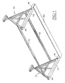
- FIG. 5 is a plan view of a stabilizing assembly.
- FIG. 6 is a fragmentary elevational view thereof.
- FIG. 7 is a sectional view taken along the line 7 — 7 in FIG. 6 .
- FIG. 8 is an exploded view of another modified from of sheet bending brake and stabilizing assembly.
- FIG. 9 is a fragmentary plan view of a portion of the sheet bending brake set forth in FIG. 8 .
- FIG. 10 is a perspective view of a another form of stabilizing assembly for use with a sheet bending brake.
- FIG. 11 is a bottom perspective view of the stabilizing assembly shown in FIG. 10 .
- FIG. 12 is a perspective view of a modified form of stabilizing assembly.
- FIG. 13 is an end view of the stabilizing assembly shown in FIG. 12 .
- the sheet bending brake embodying the invention comprises longitudinally spaced C-shaped frame members 10 .
- Each frame member includes a lower arm 11 and an upper arm 12 which overlies the lower arm 11 in spaced relation thereto. Legs may be provided as needed to support the brake above the floor or working area.
- a first fixed member 13 is fixed on the ends of the free lower arms 11 and defines a clamping surface 14 .
- a longitudinally spaced base rail 15 is fixed to the rear end of the lower arms 11 .
- a second bending member 16 is hinged to the first member 13 , as presently described, to provide a means for bending the sheet material.
- Clamping anvil member 17 extends longitudinally in overlying relationship to the clamping surface 14 of the first member 13 .
- Means are provided for moving the anvil member toward and away from the clamping surface to clamp a workpiece on the clamping surface.
- the means for clamping the workpiece may comprise any of the structures set forth in the aforementioned United States patents, incorporated herein by reference, but as herein shown comprise channel shaped pivot bars 18 pivoted on each frame member 10 with the clamping member 17 fixed thereto and a handle member 19 pivoted to the upper arm 12 of each C-frame member 10 and to the pivot bars 18 by a plurality of extensible links 19 a pivoted at the upper edge to the handle member 19 and at the lower end to the pivot bars 18 .
- the extensible links 19 a may be of the type shown in U.S. Pat. No. 4,766,757, incorporated herein by reference.
- the first member 13 having the clamping surface 14 is formed as an aluminum extrusion and includes an upper tubular portion 20 and a lower portion 21 including spaced flanges 22 engaging the free ends of lower arms 11 .
- a plurality of longitudinally spaced projections 23 are provided at the juncture of the portion 20 which defines the clamping surface 14 .
- Each projection 23 has a slot 24 formed therein and the slots 24 of the various projections 23 are in longitudinal alignment.
- Each slot 24 has its lower ends spaced from the clamping surface A and extends outwardly and upwardly so that its upper end is generally near the plane of the clamping surface.
- Each slot 24 is preferably arcuate and has a center spaced from the clamping surface and preferably extends for substantially 90 degrees.
- the bending member 16 is also in the form of an extrusion including a tubular portion 25 and a longitudinally extending leg 26 with a plurality of longitudinally spaced projections 27 having openings 28 therein.
- the projections 27 of the bending member 16 mesh with the projections 23 of the fixed member 13 and a pin 29 extends through the openings 28 and slots 24 to hinge the bending member 16 to the fixed member 13 .
- the bending member 16 further includes a portion 30 that extends upwardly and outwardly when the bending member 16 is in position for bending and has a contacting portion defined by a longitudinally extending plastic strip 31 positioned in a recess 32 .
- the recess is generally L-shaped and the strip 31 includes a short leg 33 having an enlarged end portion 34 for holding the strip 31 and the other leg 35 thereof extends along the recess beyond the portion to define a sheet contacting portion strip is preferably made of polyurethane having a durometer of 60 on the A scale.
- the fixed member 13 further includes a recess 36 extending longitudinally at the juncture of the clamping surface 14 and the projections 23 .
- Recess 36 functions as a pocket into which any burrs may fall from a knife used for scoring the workpiece.
- the clamping surface 14 is spaced slightly above the projections 23 in order to minimize marring of the surface of the workpiece when it is inserted and removed.
- the bending member 16 also includes a recess 37 extending longitudinally between the projections 27 and the contacting portion 31 .
- a workpiece of sheet material is clamped against the clamping surface 14 and the bending member 16 is moved by swinging the handle bringing the contacting portion of the bending member 16 in engagement with the sheet material.
- the hinge pin 29 on the bending member 16 moves along the slots 24 and is guided in a fashion such that the contacting portion maintains substantially the same relative position of contact thereby minimizing marring of the surface of sheet material.
- the arcuate slots 24 extend generally from below the nose or bending edge of the clamping member upwardly and outwardly toward the user so that the hinge pin 16 moves along slots 24 as the workpiece is being bent until the hinge pin 29 reaches the upper end of the slots 24 (FIG. 6) after which the bending member 16 can be moved further to bend the workpiece into contact with the upper inclined surface of the clamping member 17 .
- the handle member 19 which is connected to the members 10 by pins 41 and to the links 19 by pins 2 is provided with recesses 43 , 44 defined by integral portions 45 , 46 , 47 and 48 , respectively, that are positioned so that the recesses 43 , 44 lie substantially in the circle of the body of metal of the hollow handle member 19 thereby improving substantially the strength of the handle member.
- anvil or clamping member 17 is formed so that it has a tubular cross section including a heavy upper wall 49 and a lighter lower wall 50 generally parallel to the wall 49 and connected thereto by integral inclined portions 51 , 52 .
- the tubular portion extends rearwardly from the clamping portion 53 . It has been found that such a construction contributes substantially to the strength of the sheet bending brake and the resultant ability to bend relatively thick sheet metal.
- a stabilizing assembly is added to the legs 55 which may be fixed or folded and attached to the members 13 and 15 .
- the stabilizing assembly comprises spaced tubular transverse rails 56 which are preferably rectangular in cross section having openings 58 , 59 for receiving the feet 60 , 61 of the legs 55 .
- Longitudinally extending hollow rails 62 , 63 are fixed to extend lengthwise of the brake between the rails 56 .
- the feet 60 , 61 are preferably locked to the rails 56 by a pin 65 extending through the feet 60 , 61 and the rails 56 , 57 .
- the pin 65 is retained by a clip 66 that is hinged to the head of the pin 65 and releasably connected to the free end of the pin 65 as shown in FIG. 7 .
- a person utilizing the sheet bending brake inserts the sheet and clamps it in position by manipulating the handle 19 .
- the person further places one or both feet on one or both of the rails 62 , 63 and simultaneously lifts the bending member 16 by means of one or more handles H.
- two person of less stature may manipulate the brake by each person grasping a handle and placing one or both feet on the rails of the stabilizing assembly.
- a sheet bending brake embodying the invention is portable and yet permits bending of the sheet material which has a thickness substantially more than that heretofore thought possible.
- the stabilizing assembly comprises a flat metal transverse rail 56 a and a flat metal longitudinal rail 62 a rigidly attached to rail 56 a.
- An upstanding tubular portion 56 c is fixed on the end of transverse rail 56 b and receives the foot 60 of the legs nearest the user.
- a bolt or lock pin 66 e attaches each foot 60 and tubular portions 56 c.
- the sheet bending brake is supported on triangular folding leg assemblies 70 interconnected by longitudinal members 72 .
- the legs assemblies 70 are foldable as more specifically defined in copending application Ser. No. 08/484,977 filed Jun. 7, 1995, incorporated herein by reference.
- the stabilizing assembly comprises transverse rails 74 that are U shaped in cross section and receive the legs 76 , 78 , 80 of the leg assemblies 70 .
- the stabilizing assembly further includes a flat metal longitudinally extending rail 82 rigidly attached to the underside of the transverse rails 74 .
- the legs 76 , 78 , 80 are attached to the upstanding walls 84 of transverse rails 74 by lock pins 86 or bolts.
- the stabilizing assembly comprises a unitary construction of metal or plastic including transverse rails 90 rigidly connected to a flat longitudinal rail 92 at the forward end of the transverse rails 90 and a rear transverse rail 94 .
- Each transverse rail is U-shaped in cross section as at 96 .
- the legs of the sheet bending brake are received in the U-shaped portion at the rear of the transverse rails 92 at the juncture with rear rail 94 and are rigidly connected thereto by suitable means such as pins or clips.
- a sheet bending brake and stabilizing assembly wherein the sheet bending brake alone is constructed and arranged such that when a workpiece of increased thickness is clamped for bending when a person stands on the floor facing the handle means and the handles means is grasped and raised in a direction away from the person in order to move the handle means and raise the handle means, forces occur which prevent the handle means from moving sufficiently to produce a predetermined bend and the forces cause the entire sheet bending brake to tip away from the person about the portions of the legs which project outwardly from said bending brake which prevent the movement of the bending member relative to the first member and prevent bending of the workpiece.
- the stabilizing assembly for counteracting such forces on the sheet bending brake comprises transversely spaced rails receiving at least a portion of the ends of leg assemblies.
- the transversely spaced rails which receive at least a portion of said leg assemblies having portions extend outwardly from beneath the sheet bending brake beyond the brake toward the side of the brake from which said handle member and handle means are accessible.
- Longitudinally extending rail means interconnecting the transverse rails. The longitudinally extending rail are attached to said portions.
- the weight and positioning of the sheet bending brake, leg assemblies and rail are such that in the absence of said stabilizing assembly when bending thicker metal by a person standing on the floor and facing the side of the brake, grasping and raising the handle means, the forces opposing bending are not counteracted and the bending can not be achieved and such that the person must place one foot or both feet on the longitudinally extending rail means during the movement of the bending member away from the person for performing the bending to a desired bend without tipping of the bending brake away from the person and permit movement of the bending ember relative to the first member to bend the workpiece.
Landscapes
- Engineering & Computer Science (AREA)
- Mechanical Engineering (AREA)
- Bending Of Plates, Rods, And Pipes (AREA)
Abstract
Description
| TABLE | |||||||
| | THICKNESS | ALLOY | 90 BEND | 180 BEND | TEMPER HARDNESS | ||
| ALUM. COIL | .050 | 1100 | X | X | 0 thru H14 | |
| .0453 | 3003 | X | X | 0 thru H14 | ||
| .0453 | 5005 | X | X | 0 thru H14 | ||
| .0453 | 5052 | X | X | 0 | ||
| ALUM. SHEET | .032 | 6061 | X | T4/T6 | ||
| .040 | 1100 | X | X | 0 thru H14 | ||
| .040 | 3003 | X | X | 0 thru H14 | ||
| .040 | 5005 | X | X | 0 thru H14 | ||
| .040 | 5052 | X | X | 0 thru H14 | ||
| .040 | 6061 | X | X | 0 | ||
| COLD ROLLED |
21 ga. | .0329 | low carbon | X | X | ASTM/A366 |
| SHEET COIL | ||||||
| COMMERCIAL QUALITY | ||||||
| HOT ROLLED |
20 ga. | .0359 | X | X | ASTM/A620 | |
| SHEET & COIL | ||||||
| DRAWING QUALITY | ||||||
| GALV. |
20 ga. | .040 | X | ASTM 526 | ||
| SHEET & |
20 ga. | .040 | ASTM 527 | |||
| 24 ga. | .028 | X | X | ASTM 527 | ||
| |
24 oz. | .0324 | soft | X | X | ASTM B-152 |
| COLD ROLLED ANNEALED | 24 oz. | .0324 | soft | X | X | ASTM B-152 |
| COPPER ROLL | ||||||
| COLD ROLLED |
24 oz. | .0324 | ⅛ to ¼ hard | X | ASTM B-152 | |
| 16 oz. | .0216 | ⅛ to ¼ | X | ASTM B-152 | ||
| STAINLESS SHEET & |
24 ga. | .0324 | type 304 & 3041 | X | ⅛ HARD | |
| 24 ga. | .0324 | 316 | X | ¼ HARD | ||
| BRASS SHEET & |
20 ga. | .0320 | CDA260 | X | X | ½ HARD |
| MATERIAL BENDING CAPABILITIES |
| ULTRA XL | ||||||
| MATERIAL | WINDY | SUPER | WINDY HD | SUPER HD | PRO T.S. | PRO HD |
| Soft Alum. | .030 | .030 | .035 | .035 | .030 | .035 |
| Hard Alum. | .022 | .022 | .025 | .025 | .022 | .025 |
| Galv. |
29 |
29 |
26 |
26 |
29 |
26 |
| Copper | ||||||
| 16 |
16 |
16 |
16 oz | |||
| Vinyl | ALL STANDARD VINYL SIDINGS |
Claims (9)
Priority Applications (1)
| Application Number | Priority Date | Filing Date | Title |
|---|---|---|---|
| US09/498,281 US6389864B1 (en) | 1991-11-26 | 2000-02-04 | Heavy duty sheet bending brake |
Applications Claiming Priority (6)
| Application Number | Priority Date | Filing Date | Title |
|---|---|---|---|
| US79820791A | 1991-11-26 | 1991-11-26 | |
| US07/987,249 US5343728A (en) | 1991-11-26 | 1992-12-07 | Heavy duty sheet bending brake |
| US08/268,808 US5582055A (en) | 1991-11-26 | 1994-06-30 | Heavy duty sheet bending brake |
| US08/756,608 US5743129A (en) | 1991-11-26 | 1996-11-26 | Heavy duty sheet bending brake |
| US09/067,131 US6085569A (en) | 1991-11-26 | 1998-04-27 | Heavy duty sheet bending brake |
| US09/498,281 US6389864B1 (en) | 1991-11-26 | 2000-02-04 | Heavy duty sheet bending brake |
Related Parent Applications (1)
| Application Number | Title | Priority Date | Filing Date |
|---|---|---|---|
| US09/067,131 Continuation US6085569A (en) | 1991-11-26 | 1998-04-27 | Heavy duty sheet bending brake |
Publications (1)
| Publication Number | Publication Date |
|---|---|
| US6389864B1 true US6389864B1 (en) | 2002-05-21 |
Family
ID=27402111
Family Applications (3)
| Application Number | Title | Priority Date | Filing Date |
|---|---|---|---|
| US08/756,608 Expired - Lifetime US5743129A (en) | 1991-11-26 | 1996-11-26 | Heavy duty sheet bending brake |
| US09/067,131 Expired - Fee Related US6085569A (en) | 1991-11-26 | 1998-04-27 | Heavy duty sheet bending brake |
| US09/498,281 Expired - Fee Related US6389864B1 (en) | 1991-11-26 | 2000-02-04 | Heavy duty sheet bending brake |
Family Applications Before (2)
| Application Number | Title | Priority Date | Filing Date |
|---|---|---|---|
| US08/756,608 Expired - Lifetime US5743129A (en) | 1991-11-26 | 1996-11-26 | Heavy duty sheet bending brake |
| US09/067,131 Expired - Fee Related US6085569A (en) | 1991-11-26 | 1998-04-27 | Heavy duty sheet bending brake |
Country Status (1)
| Country | Link |
|---|---|
| US (3) | US5743129A (en) |
Cited By (23)
| Publication number | Priority date | Publication date | Assignee | Title |
|---|---|---|---|---|
| US20070277577A1 (en) * | 2004-10-29 | 2007-12-06 | Allen Clyde G | Sheet metal brake and hinge mechanism therefor |
| US20080216549A1 (en) * | 2003-11-14 | 2008-09-11 | Tapco International Corporation | Sheet metal bending brake |
| US20080223102A1 (en) * | 2007-03-16 | 2008-09-18 | Alum-A-Pole Corporation | Spring clamp for a support leg |
| US8371541B2 (en) * | 2011-03-28 | 2013-02-12 | Van Mark Products Corporation | Portable tool stand |
| US20130264452A1 (en) * | 2012-04-10 | 2013-10-10 | Peter Vanagan | Fly form table with adjustable legs |
| WO2015019213A1 (en) | 2013-08-09 | 2015-02-12 | Kimberly-Clark Worldwide, Inc. | Microparticles having a multimodal pore distribution |
| WO2015019211A1 (en) | 2013-08-09 | 2015-02-12 | Kimberly-Clark Worldwide, Inc. | Delivery system for active agents |
| WO2015019202A1 (en) | 2013-08-09 | 2015-02-12 | Kimberly-Clark Worldwide, Inc. | Technique for selectively controlling the porosity of a polymeric material |
| US9079233B2 (en) | 2013-02-11 | 2015-07-14 | Alexandre Cloutier | Gauge kits for sheet bending brakes |
| US9957369B2 (en) | 2013-08-09 | 2018-05-01 | Kimberly-Clark Worldwide, Inc. | Anisotropic polymeric material |
| US10240260B2 (en) | 2013-06-12 | 2019-03-26 | Kimberly-Clark Worldwide, Inc. | Absorbent article containing a nonwoven web formed from a porous polyolefin fibers |
| US10286593B2 (en) | 2014-06-06 | 2019-05-14 | Kimberly-Clark Worldwide, Inc. | Thermoformed article formed from a porous polymeric sheet |
| US10377108B2 (en) | 2012-02-17 | 2019-08-13 | United States Gypsum Company | Gypsum products with high efficiency heat sink additives |
| US10752745B2 (en) | 2013-06-12 | 2020-08-25 | Kimberly-Clark Worldwide, Inc. | Polyolefin film for use in packaging |
| US10849800B2 (en) | 2015-01-30 | 2020-12-01 | Kimberly-Clark Worldwide, Inc. | Film with reduced noise for use in an absorbent article |
| US10857705B2 (en) | 2013-06-12 | 2020-12-08 | Kimberly-Clark Worldwide, Inc. | Pore initiation technique |
| US10869790B2 (en) | 2015-01-30 | 2020-12-22 | Kimberly-Clark Worldwide, Inc. | Absorbent article package with reduced noise |
| US10919229B2 (en) | 2013-08-09 | 2021-02-16 | Kimberly-Clark Worldwide, Inc. | Polymeric material for three-dimensional printing |
| US11084916B2 (en) | 2013-06-12 | 2021-08-10 | Kimberly-Clark Worldwide, Inc. | Polymeric material with a multimodal pore size distribution |
| US11186927B2 (en) | 2014-06-06 | 2021-11-30 | Kimberly Clark Worldwide, Inc. | Hollow porous fibers |
| US11286362B2 (en) | 2013-06-12 | 2022-03-29 | Kimberly-Clark Worldwide, Inc. | Polymeric material for use in thermal insulation |
| US11434340B2 (en) | 2013-08-09 | 2022-09-06 | Kimberly-Clark Worldwide, Inc. | Flexible polymeric material with shape retention properties |
| US11965083B2 (en) | 2013-06-12 | 2024-04-23 | Kimberly-Clark Worldwide, Inc. | Polyolefin material having a low density |
Families Citing this family (8)
| Publication number | Priority date | Publication date | Assignee | Title |
|---|---|---|---|---|
| US6435460B1 (en) | 1999-11-04 | 2002-08-20 | Van Mark Products Corporation | Portable tool support stand |
| USD437864S1 (en) | 1999-11-04 | 2001-02-20 | Van Mark Products Corporation | Portable bending brake stand |
| JP4318455B2 (en) * | 2000-10-12 | 2009-08-26 | 三洋電機株式会社 | Color filter forming method, light emitting element layer forming method, color display device manufacturing method using the same, or color display device |
| US6675619B2 (en) * | 2001-02-09 | 2004-01-13 | Tapco International Corporation | Sheet bending brake |
| US6854314B2 (en) | 2001-09-14 | 2005-02-15 | Van Mark Products Corporation | Sheet metal tool stand |
| US6571594B2 (en) | 2001-11-02 | 2003-06-03 | Tapco International, Inc. | Open back brake |
| US7080538B1 (en) * | 2003-10-28 | 2006-07-25 | Swenson Shear | Roofing panel notching, shearing, and hemming tool |
| CN114798821B (en) * | 2021-11-16 | 2024-04-12 | 南京蓝昊智能科技有限公司 | Metal plate borrowing bending method |
Citations (21)
| Publication number | Priority date | Publication date | Assignee | Title |
|---|---|---|---|---|
| US131239A (en) | 1872-09-10 | Improvement in machines for making metallic moldings | ||
| US934701A (en) | 1908-09-05 | 1909-09-21 | John M Swanson | Mechanical hammer. |
| US2181566A (en) | 1936-06-29 | 1939-11-28 | Whitney Metal Tool Company | Portable bending brake |
| US2343441A (en) | 1941-10-21 | 1944-03-07 | Nat Supply Co | Bending brake |
| US2434028A (en) | 1945-03-29 | 1948-01-06 | Wieland Roy | Machine for bending edges of sheet metal plates |
| US3161223A (en) | 1963-10-09 | 1964-12-15 | Walter G Marsh | Sheet metal brake |
| FR1394222A (en) | 1964-02-12 | 1965-04-02 | Industrial sewing machine frame | |
| CH403677A (en) | 1963-06-21 | 1965-11-30 | Pirchegger Erwin | Collapsible jack |
| US3481173A (en) | 1967-11-30 | 1969-12-02 | Ford Motor Co | Means for forming heat exchange elements |
| US3481174A (en) | 1967-06-19 | 1969-12-02 | Henry C Barnack | Sheet metal brake |
| US3482427A (en) | 1968-05-06 | 1969-12-09 | Henry C Barnack | Sheet metal brake |
| US3559444A (en) | 1968-03-04 | 1971-02-02 | Tapco Products Co | Brake for bending sheet material |
| US3817075A (en) | 1973-03-01 | 1974-06-18 | Tapco Products Co | Sheet metal brake |
| US3872755A (en) | 1973-07-16 | 1975-03-25 | Tapco Products Co | Saw table |
| US4223881A (en) | 1968-03-04 | 1980-09-23 | Inventec International Limited | Workbenches |
| US4321817A (en) | 1980-03-17 | 1982-03-30 | Tapco Products Company, Inc. | Sheet bending brake |
| US4372142A (en) | 1980-11-28 | 1983-02-08 | Tapco Products Company, Inc. | Sheet bending brake |
| US4494397A (en) | 1982-03-18 | 1985-01-22 | Tapco Products Company, Inc. | Portable sheet bending brake |
| US4557132A (en) | 1984-02-03 | 1985-12-10 | Tapco Products Company, Inc. | Sheet bending brake |
| US4713957A (en) | 1986-08-12 | 1987-12-22 | Eder Ernest J | Reverse bend attachment for a sheet metal brake |
| GB2206069A (en) | 1987-06-16 | 1988-12-29 | William Samuel Rutherford | Pipe bending apparatus |
-
1996
- 1996-11-26 US US08/756,608 patent/US5743129A/en not_active Expired - Lifetime
-
1998
- 1998-04-27 US US09/067,131 patent/US6085569A/en not_active Expired - Fee Related
-
2000
- 2000-02-04 US US09/498,281 patent/US6389864B1/en not_active Expired - Fee Related
Patent Citations (21)
| Publication number | Priority date | Publication date | Assignee | Title |
|---|---|---|---|---|
| US131239A (en) | 1872-09-10 | Improvement in machines for making metallic moldings | ||
| US934701A (en) | 1908-09-05 | 1909-09-21 | John M Swanson | Mechanical hammer. |
| US2181566A (en) | 1936-06-29 | 1939-11-28 | Whitney Metal Tool Company | Portable bending brake |
| US2343441A (en) | 1941-10-21 | 1944-03-07 | Nat Supply Co | Bending brake |
| US2434028A (en) | 1945-03-29 | 1948-01-06 | Wieland Roy | Machine for bending edges of sheet metal plates |
| CH403677A (en) | 1963-06-21 | 1965-11-30 | Pirchegger Erwin | Collapsible jack |
| US3161223A (en) | 1963-10-09 | 1964-12-15 | Walter G Marsh | Sheet metal brake |
| FR1394222A (en) | 1964-02-12 | 1965-04-02 | Industrial sewing machine frame | |
| US3481174A (en) | 1967-06-19 | 1969-12-02 | Henry C Barnack | Sheet metal brake |
| US3481173A (en) | 1967-11-30 | 1969-12-02 | Ford Motor Co | Means for forming heat exchange elements |
| US4223881A (en) | 1968-03-04 | 1980-09-23 | Inventec International Limited | Workbenches |
| US3559444A (en) | 1968-03-04 | 1971-02-02 | Tapco Products Co | Brake for bending sheet material |
| US3482427A (en) | 1968-05-06 | 1969-12-09 | Henry C Barnack | Sheet metal brake |
| US3817075A (en) | 1973-03-01 | 1974-06-18 | Tapco Products Co | Sheet metal brake |
| US3872755A (en) | 1973-07-16 | 1975-03-25 | Tapco Products Co | Saw table |
| US4321817A (en) | 1980-03-17 | 1982-03-30 | Tapco Products Company, Inc. | Sheet bending brake |
| US4372142A (en) | 1980-11-28 | 1983-02-08 | Tapco Products Company, Inc. | Sheet bending brake |
| US4494397A (en) | 1982-03-18 | 1985-01-22 | Tapco Products Company, Inc. | Portable sheet bending brake |
| US4557132A (en) | 1984-02-03 | 1985-12-10 | Tapco Products Company, Inc. | Sheet bending brake |
| US4713957A (en) | 1986-08-12 | 1987-12-22 | Eder Ernest J | Reverse bend attachment for a sheet metal brake |
| GB2206069A (en) | 1987-06-16 | 1988-12-29 | William Samuel Rutherford | Pipe bending apparatus |
Non-Patent Citations (1)
| Title |
|---|
| Tapco International Corporation v. Van Mark Products Corporation, Case No. 00-1025 (Fed. Cir. 2001). |
Cited By (39)
| Publication number | Priority date | Publication date | Assignee | Title |
|---|---|---|---|---|
| US7549311B2 (en) | 2003-11-14 | 2009-06-23 | Tapco International Corporation | Sheet metal bending brake |
| US20080216549A1 (en) * | 2003-11-14 | 2008-09-11 | Tapco International Corporation | Sheet metal bending brake |
| US7669451B2 (en) | 2003-11-14 | 2010-03-02 | Tapco International Corporation | Sheet metal bending brake |
| US20090255315A1 (en) * | 2003-11-14 | 2009-10-15 | Tapco International Corporation | Sheet metal bending brake with improved hinge |
| US20070277577A1 (en) * | 2004-10-29 | 2007-12-06 | Allen Clyde G | Sheet metal brake and hinge mechanism therefor |
| US20080223103A1 (en) * | 2004-10-29 | 2008-09-18 | Tapco International Corporation | Sheet metal bending brake |
| US7685858B2 (en) | 2004-10-29 | 2010-03-30 | Tapco International Corporation | Sheet metal bending brake |
| US20100147046A1 (en) * | 2004-10-29 | 2010-06-17 | Tapco International Corporation | Sheet metal bending brake |
| US7954352B2 (en) | 2004-10-29 | 2011-06-07 | Tapco International Corporation | Sheet metal bending brake |
| US20110232353A1 (en) * | 2004-10-29 | 2011-09-29 | Tapco International Corporation | Sheet metal bending brake |
| US20080223102A1 (en) * | 2007-03-16 | 2008-09-18 | Alum-A-Pole Corporation | Spring clamp for a support leg |
| US8371541B2 (en) * | 2011-03-28 | 2013-02-12 | Van Mark Products Corporation | Portable tool stand |
| US10377108B2 (en) | 2012-02-17 | 2019-08-13 | United States Gypsum Company | Gypsum products with high efficiency heat sink additives |
| US20130264452A1 (en) * | 2012-04-10 | 2013-10-10 | Peter Vanagan | Fly form table with adjustable legs |
| US9079233B2 (en) | 2013-02-11 | 2015-07-14 | Alexandre Cloutier | Gauge kits for sheet bending brakes |
| US11286362B2 (en) | 2013-06-12 | 2022-03-29 | Kimberly-Clark Worldwide, Inc. | Polymeric material for use in thermal insulation |
| US11767615B2 (en) | 2013-06-12 | 2023-09-26 | Kimberly-Clark Worldwide, Inc. | Hollow porous fibers |
| US11155688B2 (en) | 2013-06-12 | 2021-10-26 | Kimberly-Clark Worldwide, Inc. | Polyolefin material having a low density |
| US10857705B2 (en) | 2013-06-12 | 2020-12-08 | Kimberly-Clark Worldwide, Inc. | Pore initiation technique |
| US11084916B2 (en) | 2013-06-12 | 2021-08-10 | Kimberly-Clark Worldwide, Inc. | Polymeric material with a multimodal pore size distribution |
| US11028246B2 (en) | 2013-06-12 | 2021-06-08 | Kimberly-Clark, Inc. | Absorbent article containing a porous polyolefin film |
| US10240260B2 (en) | 2013-06-12 | 2019-03-26 | Kimberly-Clark Worldwide, Inc. | Absorbent article containing a nonwoven web formed from a porous polyolefin fibers |
| US11001944B2 (en) | 2013-06-12 | 2021-05-11 | Kimberly-Clark Worldwide, Inc. | Porous polyolefin fibers |
| US11965083B2 (en) | 2013-06-12 | 2024-04-23 | Kimberly-Clark Worldwide, Inc. | Polyolefin material having a low density |
| US10752745B2 (en) | 2013-06-12 | 2020-08-25 | Kimberly-Clark Worldwide, Inc. | Polyolefin film for use in packaging |
| US9957369B2 (en) | 2013-08-09 | 2018-05-01 | Kimberly-Clark Worldwide, Inc. | Anisotropic polymeric material |
| US9957366B2 (en) | 2013-08-09 | 2018-05-01 | Kimberly-Clark Worldwide, Inc. | Technique for selectively controlling the porosity of a polymeric material |
| WO2015019213A1 (en) | 2013-08-09 | 2015-02-12 | Kimberly-Clark Worldwide, Inc. | Microparticles having a multimodal pore distribution |
| US10889696B2 (en) | 2013-08-09 | 2021-01-12 | Kimberly-Clark Worldwide, Inc. | Microparticles having a multimodal pore distribution |
| US10919229B2 (en) | 2013-08-09 | 2021-02-16 | Kimberly-Clark Worldwide, Inc. | Polymeric material for three-dimensional printing |
| WO2015019211A1 (en) | 2013-08-09 | 2015-02-12 | Kimberly-Clark Worldwide, Inc. | Delivery system for active agents |
| US10195157B2 (en) | 2013-08-09 | 2019-02-05 | Kimberly-Clark Worldwide, Inc. | Delivery system for active agents |
| US11434340B2 (en) | 2013-08-09 | 2022-09-06 | Kimberly-Clark Worldwide, Inc. | Flexible polymeric material with shape retention properties |
| US20160193157A1 (en) | 2013-08-09 | 2016-07-07 | Kimberly-Clark Worldwide, Inc. | Delivery System for Active Agents |
| WO2015019202A1 (en) | 2013-08-09 | 2015-02-12 | Kimberly-Clark Worldwide, Inc. | Technique for selectively controlling the porosity of a polymeric material |
| US11186927B2 (en) | 2014-06-06 | 2021-11-30 | Kimberly Clark Worldwide, Inc. | Hollow porous fibers |
| US10286593B2 (en) | 2014-06-06 | 2019-05-14 | Kimberly-Clark Worldwide, Inc. | Thermoformed article formed from a porous polymeric sheet |
| US10849800B2 (en) | 2015-01-30 | 2020-12-01 | Kimberly-Clark Worldwide, Inc. | Film with reduced noise for use in an absorbent article |
| US10869790B2 (en) | 2015-01-30 | 2020-12-22 | Kimberly-Clark Worldwide, Inc. | Absorbent article package with reduced noise |
Also Published As
| Publication number | Publication date |
|---|---|
| US5743129A (en) | 1998-04-28 |
| US6085569A (en) | 2000-07-11 |
Similar Documents
| Publication | Publication Date | Title |
|---|---|---|
| US6389864B1 (en) | Heavy duty sheet bending brake | |
| US5582055A (en) | Heavy duty sheet bending brake | |
| US4557132A (en) | Sheet bending brake | |
| US3482427A (en) | Sheet metal brake | |
| US5899132A (en) | Tilting saw table | |
| US3028197A (en) | Nestable combination table and bench structure | |
| US5706693A (en) | Combined sheet bending brake and cutter | |
| US4291869A (en) | Workbench | |
| US4321817A (en) | Sheet bending brake | |
| US4159821A (en) | Collapsible dual-height workbench | |
| US3481174A (en) | Sheet metal brake | |
| CS321891A3 (en) | Work bench with a movable top | |
| US4364254A (en) | Combined sheet bending brake, table and coil support | |
| US4445356A (en) | Combined portable sheet bending brake and coil holder | |
| US5908182A (en) | Adjustable and foldable support structure | |
| US4592518A (en) | Coil holder | |
| US4372142A (en) | Sheet bending brake | |
| US4512174A (en) | Combined sheet bending brake and platform | |
| US2181566A (en) | Portable bending brake | |
| US5505069A (en) | Sheet bending brake | |
| US6802198B2 (en) | Open back brake | |
| US6748784B1 (en) | Portable sheet bending brake | |
| US6082164A (en) | Method and apparatus for supporting and positioning a workpiece in relation to a machine | |
| US1560131A (en) | Desk | |
| CA1151516A (en) | Sheet metal brake |
Legal Events
| Date | Code | Title | Description |
|---|---|---|---|
| AS | Assignment |
Owner name: MORGAN STANLEY & CO. INCORPORATED, NEW YORK Free format text: SECURITY AGREEMENT;ASSIGNORS:HEADWATERS INCORPORATED;ACM BLOCK & BRICK GENERAL, INC.;ACM BLOCK & BRICK PARTNER, LLC,;AND OTHERS;REEL/FRAME:015896/0667 Effective date: 20040908 |
|
| AS | Assignment |
Owner name: MORGAN STANLEY & CO. INCORPORATED, NEW YORK Free format text: SECOND LIEN IP SECURITY AGREEMENT;ASSIGNORS:HEADWATERS INCORPORATED;ACM BLOCK & BRICK GENERAL, INC.;ACM BLOCK & BRICK PARTNER, LLC;AND OTHERS;REEL/FRAME:015908/0816 Effective date: 20040908 |
|
| FEPP | Fee payment procedure |
Free format text: PAYOR NUMBER ASSIGNED (ORIGINAL EVENT CODE: ASPN); ENTITY STATUS OF PATENT OWNER: LARGE ENTITY |
|
| FPAY | Fee payment |
Year of fee payment: 4 |
|
| AS | Assignment |
Owner name: HEADWATERS CTL., LLC (SUCCESSOR TO HYDROCARBON TEC Free format text: RELEASE OF SECURITY AGREEMENT;ASSIGNOR:MORGAN STANLEY & CO. INCORPORATED;REEL/FRAME:023449/0740 Effective date: 20091027 Owner name: TAPCO INTERNATIONAL CORPORATION (SUCCESSOR TO MID Free format text: RELEASE OF SECURITY AGREEMENT;ASSIGNOR:MORGAN STANLEY & CO. INCORPORATED;REEL/FRAME:023438/0778 Effective date: 20091027 Owner name: HEADWATERS RESOURCES, INC., UTAH Free format text: RELEASE OF SECURITY AGREEMENT;ASSIGNOR:MORGAN STANLEY & CO. INCORPORATED;REEL/FRAME:023449/0740 Effective date: 20091027 Owner name: HEADWATERS INCORPORATED, UTAH Free format text: RELEASE OF SECURITY AGREEMENT;ASSIGNOR:MORGAN STANLEY & CO. INCORPORATED;REEL/FRAME:023438/0778 Effective date: 20091027 Owner name: HEADWATERS CTL, LLC (SUCCESSOR TO HYDROCARBON TECH Free format text: RELEASE OF SECURITY AGREEMENT;ASSIGNOR:MORGAN STANLEY & CO. INCORPORATED;REEL/FRAME:023438/0778 Effective date: 20091027 Owner name: CURTIS-WRIGHT FLOW CONTROL CORPORATION, NEW JERSEY Free format text: RELEASE OF SECURITY AGREEMENT;ASSIGNOR:MORGAN STANLEY & CO. INCORPORATED;REEL/FRAME:023438/0778 Effective date: 20091027 Owner name: HEADWATERS RESOURCES, INC., UTAH Free format text: RELEASE OF SECURITY AGREEMENT;ASSIGNOR:MORGAN STANLEY & CO. INCORPORATED;REEL/FRAME:023438/0778 Effective date: 20091027 Owner name: CROZZOLI, GUALTIERO, ITALY Free format text: RELEASE OF SECURITY AGREEMENT;ASSIGNOR:MORGAN STANLEY & CO. INCORPORATED;REEL/FRAME:023438/0778 Effective date: 20091027 Owner name: TAPCO INTERNATIONAL CORPORATION, MICHIGAN Free format text: RELEASE OF SECURITY AGREEMENT;ASSIGNOR:MORGAN STANLEY & CO. INCORPORATED;REEL/FRAME:023438/0778 Effective date: 20091027 Owner name: TAPCO INTERNATIONAL CORPORATION (SUCCESSOR TO MID Free format text: RELEASE OF SECURITY AGREEMENT;ASSIGNOR:MORGAN STANLEY & CO. INCORPORATED;REEL/FRAME:023449/0740 Effective date: 20091027 Owner name: HEADWATERS RESOURCES, INC. (SUCCESSOR TO JTM INDUS Free format text: RELEASE OF SECURITY AGREEMENT;ASSIGNOR:MORGAN STANLEY & CO. INCORPORATED;REEL/FRAME:023438/0778 Effective date: 20091027 Owner name: TAPCO INTERNATIONAL CORPORATION (SUCCESSOR TO TAPC Free format text: RELEASE OF SECURITY AGREEMENT;ASSIGNOR:MORGAN STANLEY & CO. INCORPORATED;REEL/FRAME:023438/0778 Effective date: 20091027 Owner name: CURTIS-WRIGHT FLOW CONTROL CORPORATION, NEW JERSEY Free format text: RELEASE OF SECURITY AGREEMENT;ASSIGNOR:MORGAN STANLEY & CO. INCORPORATED;REEL/FRAME:023449/0740 Effective date: 20091027 Owner name: HEADWATERS TECHNOLOGY INNOVATION GROUP, INC. (SUCC Free format text: RELEASE OF SECURITY AGREEMENT;ASSIGNOR:MORGAN STANLEY & CO. INCORPORATED;REEL/FRAME:023449/0740 Effective date: 20091027 Owner name: TAPCO INTERNATIONAL CORPORATON (SUCCESSOR TO TAPCO Free format text: RELEASE OF SECURITY AGREEMENT;ASSIGNOR:MORGAN STANLEY & CO. INCORPORATED;REEL/FRAME:023449/0740 Effective date: 20091027 Owner name: HEADWATERS INCORPORATED, UTAH Free format text: RELEASE OF SECURITY AGREEMENT;ASSIGNOR:MORGAN STANLEY & CO. INCORPORATED;REEL/FRAME:023449/0740 Effective date: 20091027 Owner name: CROZZOLI, GUALTIERO, ITALY Free format text: RELEASE OF SECURITY AGREEMENT;ASSIGNOR:MORGAN STANLEY & CO. INCORPORATED;REEL/FRAME:023449/0740 Effective date: 20091027 Owner name: HEADWATERS TECHNOLOGY INNOVATION GROUP, INC. (SUCC Free format text: RELEASE OF SECURITY AGREEMENT;ASSIGNOR:MORGAN STANLEY & CO. INCORPORATED;REEL/FRAME:023438/0778 Effective date: 20091027 Owner name: HEADWATER RESOURCES, INC. (SUCCESSOR TO JTM INDUST Free format text: RELEASE OF SECURITY AGREEMENT;ASSIGNOR:MORGAN STANLEY & CO. INCORPORATED;REEL/FRAME:023449/0740 Effective date: 20091027 Owner name: TAPCO INTERNATIONAL CORPORATION, MICHIGAN Free format text: RELEASE OF SECURITY AGREEMENT;ASSIGNOR:MORGAN STANLEY & CO. INCORPORATED;REEL/FRAME:023449/0740 Effective date: 20091027 |
|
| AS | Assignment |
Owner name: BANK OF AMERICA, N.A., CALIFORNIA Free format text: SECURITY AGREEMENT;ASSIGNORS:HEADWATERS INCORPORATED;TAPCO INTERNATIONAL CORPORATION;HEADWATERS RESOURCES, INC.;REEL/FRAME:023449/0470 Effective date: 20091027 Owner name: BANK OF AMERICA, N.A.,CALIFORNIA Free format text: SECURITY AGREEMENT;ASSIGNORS:HEADWATERS INCORPORATED;TAPCO INTERNATIONAL CORPORATION;HEADWATERS RESOURCES, INC.;REEL/FRAME:023449/0470 Effective date: 20091027 |
|
| FPAY | Fee payment |
Year of fee payment: 8 |
|
| AS | Assignment |
Owner name: WILMINGTON TRUST FSB, AS COLLATERAL AGENT,MINNESOT Free format text: SECURITY AGREEMENT;ASSIGNORS:HEADWATERS INCORPORATED, A DELAWARE CORPORATION;HEADWATERS CTL, LLC, A UTAH LIMITED LIABILITY COMPANY, USA;HEADWATERS HEAVY OIL, LLC, A UTAH LIMITED LIABILITY COMPANY, USA;AND OTHERS;REEL/FRAME:023699/0452 Effective date: 20091027 Owner name: WILMINGTON TRUST FSB, AS COLLATERAL AGENT, MINNESO Free format text: SECURITY AGREEMENT;ASSIGNORS:HEADWATERS INCORPORATED, A DELAWARE CORPORATION;HEADWATERS CTL, LLC, A UTAH LIMITED LIABILITY COMPANY, USA;HEADWATERS HEAVY OIL, LLC, A UTAH LIMITED LIABILITY COMPANY, USA;AND OTHERS;REEL/FRAME:023699/0452 Effective date: 20091027 Owner name: WILMINGTON TRUST FSB, AS COLLATERAL AGENT, MINNESOTA Free format text: SECURITY AGREEMENT;ASSIGNORS:HEADWATERS INCORPORATED, A DELAWARE CORPORATION;HEADWATERS CTL, LLC, A UTAH LIMITED LIABILITY COMPANY, USA;HEADWATERS HEAVY OIL, LLC, A UTAH LIMITED LIABILITY COMPANY, USA;AND OTHERS;REEL/FRAME:023699/0452 Effective date: 20091027 |
|
| FEPP | Fee payment procedure |
Free format text: PAYOR NUMBER ASSIGNED (ORIGINAL EVENT CODE: ASPN); ENTITY STATUS OF PATENT OWNER: LARGE ENTITY Free format text: PAYER NUMBER DE-ASSIGNED (ORIGINAL EVENT CODE: RMPN); ENTITY STATUS OF PATENT OWNER: LARGE ENTITY |
|
| REMI | Maintenance fee reminder mailed | ||
| LAPS | Lapse for failure to pay maintenance fees | ||
| STCH | Information on status: patent discontinuation |
Free format text: PATENT EXPIRED DUE TO NONPAYMENT OF MAINTENANCE FEES UNDER 37 CFR 1.362 |
|
| FP | Lapsed due to failure to pay maintenance fee |
Effective date: 20140521 |
|
| AS | Assignment |
Owner name: TAPCO INTERNATIONAL CORPORATION, A MICHIGAN CORPORATION, UTAH Free format text: PATENT RELEASE (REEL:23699/FRAME:0452);ASSIGNOR:WILMINGTON TRUST, NATIONAL ASSOCIATION, AS COLLATERAL AGENT;REEL/FRAME:035306/0558 Effective date: 20150324 Owner name: HEADWATERS HEAVY OIL, LLC, A UTAH CORPORATION, UTAH Free format text: PATENT RELEASE (REEL:23699/FRAME:0452);ASSIGNOR:WILMINGTON TRUST, NATIONAL ASSOCIATION, AS COLLATERAL AGENT;REEL/FRAME:035306/0558 Effective date: 20150324 Owner name: HEADWATERS RESOURCES, INC., A UTAH CORPORATION, UTAH Free format text: PATENT RELEASE (REEL:23699/FRAME:0452);ASSIGNOR:WILMINGTON TRUST, NATIONAL ASSOCIATION, AS COLLATERAL AGENT;REEL/FRAME:035306/0558 Effective date: 20150324 Owner name: HEADWATERS TECHNOLOGY INNOVATION GROUP, INC., A UTAH CORPORATION, UTAH Free format text: PATENT RELEASE (REEL:23699/FRAME:0452);ASSIGNOR:WILMINGTON TRUST, NATIONAL ASSOCIATION, AS COLLATERAL AGENT;REEL/FRAME:035306/0558 Effective date: 20150324 Owner name: TAPCO INTERNATIONAL CORPORATION, A MICHIGAN CORPOR Free format text: PATENT RELEASE (REEL:23699/FRAME:0452);ASSIGNOR:WILMINGTON TRUST, NATIONAL ASSOCIATION, AS COLLATERAL AGENT;REEL/FRAME:035306/0558 Effective date: 20150324 Owner name: HEADWATERS TECHNOLOGY INNOVATION GROUP, INC., A UT Free format text: PATENT RELEASE (REEL:23699/FRAME:0452);ASSIGNOR:WILMINGTON TRUST, NATIONAL ASSOCIATION, AS COLLATERAL AGENT;REEL/FRAME:035306/0558 Effective date: 20150324 Owner name: HEADWATERS INCORPORATED, AS GRANTOR, UTAH Free format text: PATENT RELEASE (REEL:23699/FRAME:0452);ASSIGNOR:WILMINGTON TRUST, NATIONAL ASSOCIATION, AS COLLATERAL AGENT;REEL/FRAME:035306/0558 Effective date: 20150324 Owner name: HEADWATERS HEAVY OIL, LLC, A UTAH CORPORATION, UTA Free format text: PATENT RELEASE (REEL:23699/FRAME:0452);ASSIGNOR:WILMINGTON TRUST, NATIONAL ASSOCIATION, AS COLLATERAL AGENT;REEL/FRAME:035306/0558 Effective date: 20150324 Owner name: HEADWATERS RESOURCES, INC., A UTAH CORPORATION, UT Free format text: PATENT RELEASE (REEL:23699/FRAME:0452);ASSIGNOR:WILMINGTON TRUST, NATIONAL ASSOCIATION, AS COLLATERAL AGENT;REEL/FRAME:035306/0558 Effective date: 20150324 |
|
| AS | Assignment |
Owner name: TAPCO INTERNATIONAL CORPORATION, UTAH Free format text: RELEASE BY SECURED PARTY;ASSIGNOR:BANK OF AMERICA, N.A.;REEL/FRAME:042446/0199 Effective date: 20170508 Owner name: HEADWATERS INCORPORATED, UTAH Free format text: RELEASE BY SECURED PARTY;ASSIGNOR:BANK OF AMERICA, N.A.;REEL/FRAME:042446/0199 Effective date: 20170508 Owner name: HEADWATERS RESOURCES, LLC (FKA HEADWATERS RESOURCE Free format text: RELEASE BY SECURED PARTY;ASSIGNOR:BANK OF AMERICA, N.A.;REEL/FRAME:042446/0199 Effective date: 20170508 |