US5505069A - Sheet bending brake - Google Patents
Sheet bending brake Download PDFInfo
- Publication number
- US5505069A US5505069A US08/254,177 US25417794A US5505069A US 5505069 A US5505069 A US 5505069A US 25417794 A US25417794 A US 25417794A US 5505069 A US5505069 A US 5505069A
- Authority
- US
- United States
- Prior art keywords
- integral
- wall
- providing
- bending
- clamping surface
- Prior art date
- Legal status (The legal status is an assumption and is not a legal conclusion. Google has not performed a legal analysis and makes no representation as to the accuracy of the status listed.)
- Expired - Lifetime
Links
Images


Classifications
-
- B—PERFORMING OPERATIONS; TRANSPORTING
- B21—MECHANICAL METAL-WORKING WITHOUT ESSENTIALLY REMOVING MATERIAL; PUNCHING METAL
- B21D—WORKING OR PROCESSING OF SHEET METAL OR METAL TUBES, RODS OR PROFILES WITHOUT ESSENTIALLY REMOVING MATERIAL; PUNCHING METAL
- B21D5/00—Bending sheet metal along straight lines, e.g. to form simple curves
- B21D5/04—Bending sheet metal along straight lines, e.g. to form simple curves on brakes making use of clamping means on one side of the work
- B21D5/042—With a rotational movement of the bending blade
Definitions
- This invention relates to sheet bending brakes.
- Such brakes comprise a fixed member on which the sheet is clamped and a movable bending member for bending the sheet.
- a major problem with respect to such sheet bending brakes is the tendency of the bending member to move relative to the portion of the sheet being bent and thereby mar the surface of the sheet.
- U.S. Pat. Nos. 3,481,174 and 3,482,427 were directed to an arrangement which included a floatable compensator on the bending member which engages the sheet material and as the bending member is swung to bend the sheet pivots so that the contact with the sheet material is maintained.
- each of the fixed and movable bending members have substantially the entire length of the longitudinal edges thereof formed with longitudinally spaced intermeshing integral projections.
- the projections on the bending member having a plurality of aligned openings and the projections on the fixed member have a plurality of aligned openings comprising slots extending axially with respect to the longitudinal axis of said member.
- a hinge pin extends through the openings of said bending member and the slots of the fixed member.
- the slots have a configuration such that as the bending member is moved relative to the fixed member to bend a workpiece, the hinge pin is guided along said slots such that the contacting portion of the bending member remains substantially in the same position relative to the workpiece.
- a sheet bending brake which has an improved clamping surface; which provides greater depth for receipt of workpieces to be bent; and which is stronger in construction.
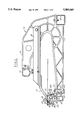
- FIG. 1 is an end elevational view of a sheet bending brake embodying the invention.
- FIG. 2 is an elevational view of a portion of the brake shown in FIG. 1 on an enlarged scale.
- FIGS. 3 and 3 are similar to FIGS. 1 and 2 but show the the brake in different operating positions.
- FIG. 5 is a fragmentary perspective view of a portion of the bending member.
- FIG. 6 is a fragmentary perspective view of a portion of the fixed member.
- FIG. 7 is an enlarged perspective view of the fixed member shown in FIG. 6.
- FIG. 8 is a perspective view of the fixed member taken from the left as viewed in FIG. 7.
- FIG. 9 is a fragmentary perspective view of a wear plate utilized on the fixed member.
- FIGS. 10, 11 and 12 are fragmentary end views showing portions of the sheet bending brake in different operative positions.
- the sheet bending brake embodying the invention comprises longitudinally spaced C-shaped frame members 10.
- Each frame member 10 includes a lower arm 11 and an upper arm 12 which overlies the lower arm 11 in spaced relation thereto. Legs may be provided as needed to support the brake above the floor or working area.
- a first extruded fixed member 13 is fixed on the ends of the free lower arms 11 and defines a clamping surface 14. Longitudinally spaced base rails 15 are fixed to the rear end of the lower arms 11.
- a second extruded bending member 16 is hinged to the first member 13, as presently described, to provide a means for bending the sheet material.
- Clamping member 17 extends longitudinally in overlying relationship to the clamping surface 14 of the first member 13. Means are provided for moving the anvil member toward and away from the clamping surface to clamp a workpiece on the clamping surface.
- the means for clamping the workpiece may comprise any of the structures set forth in the aforementioned United States Patents, incorporated herein by reference, but as herein shown comprise channel shaped pivot bars 18 pivoted on each frame member 10 with the clamping member 17 fixed thereto and handle member 19 pivoted to the upper arm 12 of each C-frame member 10 and to the pivot bars 18 by a plurality of extensible links 19 pivoted at the upper edge to the handle member 19 and at the lower end to the pivot bars 18.
- the extensible links may be of the type shown in U.S. Pat. No.
- the first member 13 having the clamping surface 14 is formed as an aluminum extrusion and includes an upper tubular portion 20 and a lower portion 21 including spaced flanges 22 engaging the free ends of lower arms 11.
- a plurality of longitudinally spaced projections 23 are provided at the juncture of the portion 20 which defines the clamping surface 14.
- Each projection 23 has a slot 24 formed therein and the slots 24 of the various projections 23 are in longitudinal alignment.
- Each slot 24 has its lower ends spaced from the clamping surface A and extends outwardly and upwardly so that its upper end is generally near the plane of the clamping surface.
- Each slot 24 is preferably arcuate and has a center spaced from the clamping surface and preferably extends for substantially 90°.
- the bending member 16 is also in the form of an extrusion including a tubular portion 25 and a longitudinally extending leg 26 with a plurality of longitudinally spaced projections 27 having openings 28 therein.
- the projections 27 of the bending member 16 mesh with the projections 23 of the fixed member 13 and a pin 29 extends through the openings 28 and slots 24 to hinge the bending member 16 to the fixed member 13.
- the bending member 16 further includes a portion 30 that extends upwardly and outwardly when the bending member 16 is in position for bending and has a contacting portion defined by a longitudinally extending plastic strip 31 positioned in a recess 32.
- the recess is generally L-shaped and the strip 31 includes a short leg 33 having an enlarged end portion 34 for holding the strip 31 and the other leg 35 thereof extends along the recess beyond the portion to define a sheet contacting portion.
- Strip is preferably made of polyurethane having a durometer of 60 on the A scale.
- the fixed member 13 further includes a recess 36 extending longitudinally at the juncture of the clamping surface 14 and the projections 23.
- Recess 36 functions as a pocket into which any burrs may fall from a knife used for scoring the workpiece.
- the clamping surface 14 is spaced slightly above the projections 23 in order to minimize marring of the surface of the workpiece when it is inserted and removed.
- the bending member 16 also includes a recess 37 extending longitudinally between the projections 27 and the contacting portion 31.
- a workpiece of sheet material is clamped against the clamping surface 14 and the bending member 16 is moved by swinging the handle bringing the contacting portion of the bending member 16 in engagement with the sheet material.
- the hinge pin 29 on the bending member 16 moves along the slots 24 and is guided in a fashion such that the contacting portion maintains substantially the same relative position of contact thereby minimizing marring of the surface of sheet material.
- the arcuate slots 24 extend generally from below the nose or bending edge of the clamping member upwardly and outwardly toward the user so that the hinge 16 moves along slots 24 as the workpiece is being bent until the hinge pin 29 reaches the upper end of the slots 24 (FIG. 6) after which the bending member 16 can be moved further to bend the workpiece into contact with the upper inclined surface of the clamping member 17.
- Hemming can thereafter be achieved by unclamping the workpiece and placing the apex of the bend which has been formed on the workpiece in contact with the nose of the clamping member 16 and swinging the bending member 16 to compress and flatten the two bent portions of the workpiece against the upper surface of the clamping member 17.
- the bend can be interrupted at any time and begin without marring the surface of the workpiece.
- the workpiece can be bent with only a short portion extending beyond the nose of the clamping member 17, for example, a 1/4".
- the use of slots 24 also facilitates assembly of the hinge pin 29 and makes the member 13 easier to extrude.
- the upper tubular portion 20 of the member 13 comprises an outer wall 40 that extends upwardly and outwardly from the vertical wall 41 of the lower portion; an integral horizontal wall 42; and integral rear wall 43 that extends downwardly and inwardly to the front edge of the upper flange 22.
- the outer wall 40 and rear wall 43 converge downwardly with respect to one another.
- Rear wall 43 includes a recessed portion 44 for receiving a hook 45 on the rear edge of a stainless steel wear plate 46.
- the front edge 47 of plate 46 includes a hook 48 engaging recess 36.
- An integral web 44a extends from the recessed portion 44 to the rear surface of the front wall 40.
- the clamping member 17 further includes a protective metal strip of sheet metal such as stainless steel having edges received in corresponding received in corresponding recesses as shown in U.S. Pat. No. 4,651,553, incorporated herein by reference.
- a protective metal strip of sheet metal such as stainless steel having edges received in corresponding received in corresponding recesses as shown in U.S. Pat. No. 4,651,553, incorporated herein by reference.
- the construction strengthens the bending brake and more specifically the fixed member 13 while also providing a protective bearing surface on the horizontal wall against which the workpiece is clamped.
- the sheet bending brake embodying the invention provides an improved clamping surface and a greater depth of throat for receiving workpieces which are to be bent.
Abstract
Description
Claims (6)
Priority Applications (1)
| Application Number | Priority Date | Filing Date | Title |
|---|---|---|---|
| US08/254,177 US5505069A (en) | 1994-06-06 | 1994-06-06 | Sheet bending brake |
Applications Claiming Priority (1)
| Application Number | Priority Date | Filing Date | Title |
|---|---|---|---|
| US08/254,177 US5505069A (en) | 1994-06-06 | 1994-06-06 | Sheet bending brake |
Publications (1)
| Publication Number | Publication Date |
|---|---|
| US5505069A true US5505069A (en) | 1996-04-09 |
Family
ID=22963230
Family Applications (1)
| Application Number | Title | Priority Date | Filing Date |
|---|---|---|---|
| US08/254,177 Expired - Lifetime US5505069A (en) | 1994-06-06 | 1994-06-06 | Sheet bending brake |
Country Status (1)
| Country | Link |
|---|---|
| US (1) | US5505069A (en) |
Cited By (8)
| Publication number | Priority date | Publication date | Assignee | Title |
|---|---|---|---|---|
| US5899000A (en) * | 1996-10-30 | 1999-05-04 | Break; Douglas G. | Hand held cutter |
| US6532789B1 (en) | 2001-02-26 | 2003-03-18 | J-Dan, Inc. | Portable sheet bending brake |
| US6571594B2 (en) | 2001-11-02 | 2003-06-03 | Tapco International, Inc. | Open back brake |
| US6619096B1 (en) * | 1999-10-08 | 2003-09-16 | Unova Ip Corp. | Die post assembly |
| US20050103081A1 (en) * | 2003-11-14 | 2005-05-19 | Douglas Break | Sheet metal bending brake with improved hinge |
| US20080223103A1 (en) * | 2004-10-29 | 2008-09-18 | Tapco International Corporation | Sheet metal bending brake |
| US9079233B2 (en) | 2013-02-11 | 2015-07-14 | Alexandre Cloutier | Gauge kits for sheet bending brakes |
| RU222209U1 (en) * | 2023-10-20 | 2023-12-15 | Тимур Радисович Хайруллин | MOUNTING CAM FOR FIXING BAR OF PORTABLE PLATE BRENDING MACHINE |
Citations (18)
| Publication number | Priority date | Publication date | Assignee | Title |
|---|---|---|---|---|
| DE303138C (en) * | ||||
| FR1097242A (en) * | 1954-01-15 | 1955-07-01 | Device for suspending moving elements preventing the transmission of abnormal forces, in particular for bending machines and similar applications | |
| GB770085A (en) * | 1954-04-17 | 1957-03-13 | Johann Usspurwies G M B H | Improvements in or relating to sheet metal bending machines |
| US3161223A (en) * | 1963-10-09 | 1964-12-15 | Walter G Marsh | Sheet metal brake |
| US3481174A (en) * | 1967-06-19 | 1969-12-02 | Henry C Barnack | Sheet metal brake |
| US3482427A (en) * | 1968-05-06 | 1969-12-09 | Henry C Barnack | Sheet metal brake |
| US3559444A (en) * | 1968-03-04 | 1971-02-02 | Tapco Products Co | Brake for bending sheet material |
| US3817075A (en) * | 1973-03-01 | 1974-06-18 | Tapco Products Co | Sheet metal brake |
| US3872755A (en) * | 1973-07-16 | 1975-03-25 | Tapco Products Co | Saw table |
| US4240279A (en) * | 1978-11-27 | 1980-12-23 | Tapco Products Company, Inc. | Sheet metal brake |
| US4321817A (en) * | 1980-03-17 | 1982-03-30 | Tapco Products Company, Inc. | Sheet bending brake |
| US4372142A (en) * | 1980-11-28 | 1983-02-08 | Tapco Products Company, Inc. | Sheet bending brake |
| US4489583A (en) * | 1982-03-18 | 1984-12-25 | Tapco Products Company, Inc. | Portable sheet bending brake |
| US4493200A (en) * | 1983-03-10 | 1985-01-15 | Tapco Products Company, Inc. | Portable sheet bending brake |
| US4512174A (en) * | 1982-06-07 | 1985-04-23 | Tapco Products Company, Inc. | Combined sheet bending brake and platform |
| US4557132A (en) * | 1984-02-03 | 1985-12-10 | Tapco Products Company, Inc. | Sheet bending brake |
| US4651553A (en) * | 1982-03-18 | 1987-03-24 | Tapco Products Company, Inc. | Portable sheet bending brake |
| US4918966A (en) * | 1989-08-21 | 1990-04-24 | Raccioppi Jr Michael G | Work table for sheet metal brakes |
-
1994
- 1994-06-06 US US08/254,177 patent/US5505069A/en not_active Expired - Lifetime
Patent Citations (18)
| Publication number | Priority date | Publication date | Assignee | Title |
|---|---|---|---|---|
| DE303138C (en) * | ||||
| FR1097242A (en) * | 1954-01-15 | 1955-07-01 | Device for suspending moving elements preventing the transmission of abnormal forces, in particular for bending machines and similar applications | |
| GB770085A (en) * | 1954-04-17 | 1957-03-13 | Johann Usspurwies G M B H | Improvements in or relating to sheet metal bending machines |
| US3161223A (en) * | 1963-10-09 | 1964-12-15 | Walter G Marsh | Sheet metal brake |
| US3481174A (en) * | 1967-06-19 | 1969-12-02 | Henry C Barnack | Sheet metal brake |
| US3559444A (en) * | 1968-03-04 | 1971-02-02 | Tapco Products Co | Brake for bending sheet material |
| US3482427A (en) * | 1968-05-06 | 1969-12-09 | Henry C Barnack | Sheet metal brake |
| US3817075A (en) * | 1973-03-01 | 1974-06-18 | Tapco Products Co | Sheet metal brake |
| US3872755A (en) * | 1973-07-16 | 1975-03-25 | Tapco Products Co | Saw table |
| US4240279A (en) * | 1978-11-27 | 1980-12-23 | Tapco Products Company, Inc. | Sheet metal brake |
| US4321817A (en) * | 1980-03-17 | 1982-03-30 | Tapco Products Company, Inc. | Sheet bending brake |
| US4372142A (en) * | 1980-11-28 | 1983-02-08 | Tapco Products Company, Inc. | Sheet bending brake |
| US4489583A (en) * | 1982-03-18 | 1984-12-25 | Tapco Products Company, Inc. | Portable sheet bending brake |
| US4651553A (en) * | 1982-03-18 | 1987-03-24 | Tapco Products Company, Inc. | Portable sheet bending brake |
| US4512174A (en) * | 1982-06-07 | 1985-04-23 | Tapco Products Company, Inc. | Combined sheet bending brake and platform |
| US4493200A (en) * | 1983-03-10 | 1985-01-15 | Tapco Products Company, Inc. | Portable sheet bending brake |
| US4557132A (en) * | 1984-02-03 | 1985-12-10 | Tapco Products Company, Inc. | Sheet bending brake |
| US4918966A (en) * | 1989-08-21 | 1990-04-24 | Raccioppi Jr Michael G | Work table for sheet metal brakes |
Cited By (19)
| Publication number | Priority date | Publication date | Assignee | Title |
|---|---|---|---|---|
| US5899000A (en) * | 1996-10-30 | 1999-05-04 | Break; Douglas G. | Hand held cutter |
| US6619096B1 (en) * | 1999-10-08 | 2003-09-16 | Unova Ip Corp. | Die post assembly |
| US6532789B1 (en) | 2001-02-26 | 2003-03-18 | J-Dan, Inc. | Portable sheet bending brake |
| US6748784B1 (en) | 2001-02-26 | 2004-06-15 | J-Dan, Inc. | Portable sheet bending brake |
| US6571594B2 (en) | 2001-11-02 | 2003-06-03 | Tapco International, Inc. | Open back brake |
| US20080216549A1 (en) * | 2003-11-14 | 2008-09-11 | Tapco International Corporation | Sheet metal bending brake |
| US7669451B2 (en) | 2003-11-14 | 2010-03-02 | Tapco International Corporation | Sheet metal bending brake |
| US20070175257A1 (en) * | 2003-11-14 | 2007-08-02 | Tapco International Corporation | Sheet metal bending brake with improved hinge |
| US20050103081A1 (en) * | 2003-11-14 | 2005-05-19 | Douglas Break | Sheet metal bending brake with improved hinge |
| US7191631B2 (en) | 2003-11-14 | 2007-03-20 | Tapco International Corporation | Sheet metal bending brake with improved hinge |
| US7549311B2 (en) | 2003-11-14 | 2009-06-23 | Tapco International Corporation | Sheet metal bending brake |
| US20090255315A1 (en) * | 2003-11-14 | 2009-10-15 | Tapco International Corporation | Sheet metal bending brake with improved hinge |
| US20080223103A1 (en) * | 2004-10-29 | 2008-09-18 | Tapco International Corporation | Sheet metal bending brake |
| US7685858B2 (en) | 2004-10-29 | 2010-03-30 | Tapco International Corporation | Sheet metal bending brake |
| US20100147046A1 (en) * | 2004-10-29 | 2010-06-17 | Tapco International Corporation | Sheet metal bending brake |
| US7954352B2 (en) | 2004-10-29 | 2011-06-07 | Tapco International Corporation | Sheet metal bending brake |
| US20110232353A1 (en) * | 2004-10-29 | 2011-09-29 | Tapco International Corporation | Sheet metal bending brake |
| US9079233B2 (en) | 2013-02-11 | 2015-07-14 | Alexandre Cloutier | Gauge kits for sheet bending brakes |
| RU222209U1 (en) * | 2023-10-20 | 2023-12-15 | Тимур Радисович Хайруллин | MOUNTING CAM FOR FIXING BAR OF PORTABLE PLATE BRENDING MACHINE |
Similar Documents
| Publication | Publication Date | Title |
|---|---|---|
| US4557132A (en) | Sheet bending brake | |
| US5706693A (en) | Combined sheet bending brake and cutter | |
| US5743129A (en) | Heavy duty sheet bending brake | |
| US4574553A (en) | Spacer frame and method for bending hollow shaped bar portions to form spacer frames for insulating glass | |
| US5799557A (en) | Venetian blind cutting machine | |
| US5505069A (en) | Sheet bending brake | |
| US5992203A (en) | Coil holder for a sheet bending brake | |
| EP0544190A1 (en) | Heavy duty sheet bending brake | |
| US20070175257A1 (en) | Sheet metal bending brake with improved hinge | |
| US4321817A (en) | Sheet bending brake | |
| US4364254A (en) | Combined sheet bending brake, table and coil support | |
| US4766757A (en) | Sheet bending brake | |
| US4493200A (en) | Portable sheet bending brake | |
| US4372142A (en) | Sheet bending brake | |
| US3877279A (en) | Sheet metal brake | |
| US4445356A (en) | Combined portable sheet bending brake and coil holder | |
| US4592518A (en) | Coil holder | |
| US5899000A (en) | Hand held cutter | |
| CA2121946A1 (en) | Portable sheet bending brake | |
| WO1986006674A1 (en) | Hole punching device | |
| CN114769836A (en) | Novel friction welding tool for rotor products | |
| US6233995B1 (en) | Forming tool for a bending brake | |
| US6802198B2 (en) | Open back brake | |
| CN218775716U (en) | Intelligent perforating device is used in door and window installation | |
| GB2071540A (en) | Improvements in bending brakes |
Legal Events
| Date | Code | Title | Description |
|---|---|---|---|
| AS | Assignment |
Owner name: TAPCO INTERNATIONAL CORPORATION, MICHIGAN Free format text: ASSIGNMENT OF ASSIGNORS INTEREST;ASSIGNORS:BREAK, DOUGLAS G.;CHUBB, ARTHUR B.;CHUBB, DOUGLAS J.;AND OTHERS;REEL/FRAME:007026/0089 Effective date: 19940603 |
|
| STCF | Information on status: patent grant |
Free format text: PATENTED CASE |
|
| FEPP | Fee payment procedure |
Free format text: PAT HLDR NO LONGER CLAIMS SMALL ENT STAT AS SMALL BUSINESS (ORIGINAL EVENT CODE: LSM2); ENTITY STATUS OF PATENT OWNER: LARGE ENTITY |
|
| FPAY | Fee payment |
Year of fee payment: 4 |
|
| AS | Assignment |
Owner name: BANK ONE, MICHIGAN, MICHIGAN Free format text: SECURITY INTEREST;ASSIGNOR:ROHRBACK COSASCO SYSTEMS, INC.;REEL/FRAME:012059/0130 Effective date: 20000609 |
|
| FPAY | Fee payment |
Year of fee payment: 8 |
|
| AS | Assignment |
Owner name: MORGAN STANLEY & CO. INCORPORATED, NEW YORK Free format text: SECURITY AGREEMENT;ASSIGNORS:HEADWATERS INCORPORATED;ACM BLOCK & BRICK GENERAL, INC.;ACM BLOCK & BRICK PARTNER, LLC,;AND OTHERS;REEL/FRAME:015896/0667 Effective date: 20040908 |
|
| AS | Assignment |
Owner name: MORGAN STANLEY & CO. INCORPORATED, NEW YORK Free format text: SECOND LIEN IP SECURITY AGREEMENT;ASSIGNORS:HEADWATERS INCORPORATED;ACM BLOCK & BRICK GENERAL, INC.;ACM BLOCK & BRICK PARTNER, LLC;AND OTHERS;REEL/FRAME:015908/0816 Effective date: 20040908 |
|
| FPAY | Fee payment |
Year of fee payment: 12 |
|
| AS | Assignment |
Owner name: TAPCO INTERNATIONAL CORPORATON (SUCCESSOR TO TAPCO Free format text: RELEASE OF SECURITY AGREEMENT;ASSIGNOR:MORGAN STANLEY & CO. INCORPORATED;REEL/FRAME:023449/0740 Effective date: 20091027 Owner name: CROZZOLI, GUALTIERO, ITALY Free format text: RELEASE OF SECURITY AGREEMENT;ASSIGNOR:MORGAN STANLEY & CO. INCORPORATED;REEL/FRAME:023449/0740 Effective date: 20091027 Owner name: HEADWATER RESOURCES, INC. (SUCCESSOR TO JTM INDUST Free format text: RELEASE OF SECURITY AGREEMENT;ASSIGNOR:MORGAN STANLEY & CO. INCORPORATED;REEL/FRAME:023449/0740 Effective date: 20091027 Owner name: HEADWATERS RESOURCES, INC., UTAH Free format text: RELEASE OF SECURITY AGREEMENT;ASSIGNOR:MORGAN STANLEY & CO. INCORPORATED;REEL/FRAME:023449/0740 Effective date: 20091027 Owner name: CURTIS-WRIGHT FLOW CONTROL CORPORATION, NEW JERSEY Free format text: RELEASE OF SECURITY AGREEMENT;ASSIGNOR:MORGAN STANLEY & CO. INCORPORATED;REEL/FRAME:023438/0778 Effective date: 20091027 Owner name: HEADWATERS INCORPORATED, UTAH Free format text: RELEASE OF SECURITY AGREEMENT;ASSIGNOR:MORGAN STANLEY & CO. INCORPORATED;REEL/FRAME:023449/0740 Effective date: 20091027 Owner name: HEADWATERS TECHNOLOGY INNOVATION GROUP, INC. (SUCC Free format text: RELEASE OF SECURITY AGREEMENT;ASSIGNOR:MORGAN STANLEY & CO. INCORPORATED;REEL/FRAME:023449/0740 Effective date: 20091027 Owner name: TAPCO INTERNATIONAL CORPORATION, MICHIGAN Free format text: RELEASE OF SECURITY AGREEMENT;ASSIGNOR:MORGAN STANLEY & CO. INCORPORATED;REEL/FRAME:023449/0740 Effective date: 20091027 Owner name: HEADWATERS CTL., LLC (SUCCESSOR TO HYDROCARBON TEC Free format text: RELEASE OF SECURITY AGREEMENT;ASSIGNOR:MORGAN STANLEY & CO. INCORPORATED;REEL/FRAME:023449/0740 Effective date: 20091027 Owner name: HEADWATERS RESOURCES, INC., UTAH Free format text: RELEASE OF SECURITY AGREEMENT;ASSIGNOR:MORGAN STANLEY & CO. INCORPORATED;REEL/FRAME:023438/0778 Effective date: 20091027 Owner name: HEADWATERS CTL, LLC (SUCCESSOR TO HYDROCARBON TECH Free format text: RELEASE OF SECURITY AGREEMENT;ASSIGNOR:MORGAN STANLEY & CO. INCORPORATED;REEL/FRAME:023438/0778 Effective date: 20091027 Owner name: HEADWATERS TECHNOLOGY INNOVATION GROUP, INC. (SUCC Free format text: RELEASE OF SECURITY AGREEMENT;ASSIGNOR:MORGAN STANLEY & CO. INCORPORATED;REEL/FRAME:023438/0778 Effective date: 20091027 Owner name: HEADWATERS INCORPORATED, UTAH Free format text: RELEASE OF SECURITY AGREEMENT;ASSIGNOR:MORGAN STANLEY & CO. INCORPORATED;REEL/FRAME:023438/0778 Effective date: 20091027 Owner name: TAPCO INTERNATIONAL CORPORATION (SUCCESSOR TO TAPC Free format text: RELEASE OF SECURITY AGREEMENT;ASSIGNOR:MORGAN STANLEY & CO. INCORPORATED;REEL/FRAME:023438/0778 Effective date: 20091027 Owner name: CROZZOLI, GUALTIERO, ITALY Free format text: RELEASE OF SECURITY AGREEMENT;ASSIGNOR:MORGAN STANLEY & CO. INCORPORATED;REEL/FRAME:023438/0778 Effective date: 20091027 Owner name: CURTIS-WRIGHT FLOW CONTROL CORPORATION, NEW JERSEY Free format text: RELEASE OF SECURITY AGREEMENT;ASSIGNOR:MORGAN STANLEY & CO. INCORPORATED;REEL/FRAME:023449/0740 Effective date: 20091027 Owner name: TAPCO INTERNATIONAL CORPORATION, MICHIGAN Free format text: RELEASE OF SECURITY AGREEMENT;ASSIGNOR:MORGAN STANLEY & CO. INCORPORATED;REEL/FRAME:023438/0778 Effective date: 20091027 Owner name: TAPCO INTERNATIONAL CORPORATION (SUCCESSOR TO MID Free format text: RELEASE OF SECURITY AGREEMENT;ASSIGNOR:MORGAN STANLEY & CO. INCORPORATED;REEL/FRAME:023449/0740 Effective date: 20091027 Owner name: HEADWATERS RESOURCES, INC. (SUCCESSOR TO JTM INDUS Free format text: RELEASE OF SECURITY AGREEMENT;ASSIGNOR:MORGAN STANLEY & CO. INCORPORATED;REEL/FRAME:023438/0778 Effective date: 20091027 Owner name: TAPCO INTERNATIONAL CORPORATION (SUCCESSOR TO MID Free format text: RELEASE OF SECURITY AGREEMENT;ASSIGNOR:MORGAN STANLEY & CO. INCORPORATED;REEL/FRAME:023438/0778 Effective date: 20091027 |
|
| AS | Assignment |
Owner name: BANK OF AMERICA, N.A., CALIFORNIA Free format text: SECURITY AGREEMENT;ASSIGNORS:HEADWATERS INCORPORATED;TAPCO INTERNATIONAL CORPORATION;HEADWATERS RESOURCES, INC.;REEL/FRAME:023449/0470 Effective date: 20091027 Owner name: BANK OF AMERICA, N.A.,CALIFORNIA Free format text: SECURITY AGREEMENT;ASSIGNORS:HEADWATERS INCORPORATED;TAPCO INTERNATIONAL CORPORATION;HEADWATERS RESOURCES, INC.;REEL/FRAME:023449/0470 Effective date: 20091027 |
|
| AS | Assignment |
Owner name: WILMINGTON TRUST FSB, AS COLLATERAL AGENT,MINNESOT Free format text: SECURITY AGREEMENT;ASSIGNORS:HEADWATERS INCORPORATED, A DELAWARE CORPORATION;HEADWATERS CTL, LLC, A UTAH LIMITED LIABILITY COMPANY, USA;HEADWATERS HEAVY OIL, LLC, A UTAH LIMITED LIABILITY COMPANY, USA;AND OTHERS;REEL/FRAME:023699/0452 Effective date: 20091027 Owner name: WILMINGTON TRUST FSB, AS COLLATERAL AGENT, MINNESO Free format text: SECURITY AGREEMENT;ASSIGNORS:HEADWATERS INCORPORATED, A DELAWARE CORPORATION;HEADWATERS CTL, LLC, A UTAH LIMITED LIABILITY COMPANY, USA;HEADWATERS HEAVY OIL, LLC, A UTAH LIMITED LIABILITY COMPANY, USA;AND OTHERS;REEL/FRAME:023699/0452 Effective date: 20091027 Owner name: WILMINGTON TRUST FSB, AS COLLATERAL AGENT, MINNESOTA Free format text: SECURITY AGREEMENT;ASSIGNORS:HEADWATERS INCORPORATED, A DELAWARE CORPORATION;HEADWATERS CTL, LLC, A UTAH LIMITED LIABILITY COMPANY, USA;HEADWATERS HEAVY OIL, LLC, A UTAH LIMITED LIABILITY COMPANY, USA;AND OTHERS;REEL/FRAME:023699/0452 Effective date: 20091027 |
|
| AS | Assignment |
Owner name: ROHRBACK COSASCO SYSTEMS, INC., CALIFORNIA Free format text: RELEASE OF SECURITY AGREEMENT INTERESTS;ASSIGNOR:JPMORGAN CHASE BANK, N.A., AS SUCCESSOR BY MERGER TO BANK ONE, N.A. (CHICAGO), SUCCESSOR BY MERGER TO BANK ONE MICHIGAN;REEL/FRAME:026060/0304 Effective date: 20110218 |
|
| AS | Assignment |
Owner name: HEADWATERS TECHNOLOGY INNOVATION GROUP, INC., A UTAH CORPORATION, UTAH Free format text: PATENT RELEASE (REEL:23699/FRAME:0452);ASSIGNOR:WILMINGTON TRUST, NATIONAL ASSOCIATION, AS COLLATERAL AGENT;REEL/FRAME:035306/0558 Effective date: 20150324 Owner name: TAPCO INTERNATIONAL CORPORATION, A MICHIGAN CORPORATION, UTAH Free format text: PATENT RELEASE (REEL:23699/FRAME:0452);ASSIGNOR:WILMINGTON TRUST, NATIONAL ASSOCIATION, AS COLLATERAL AGENT;REEL/FRAME:035306/0558 Effective date: 20150324 Owner name: HEADWATERS RESOURCES, INC., A UTAH CORPORATION, UTAH Free format text: PATENT RELEASE (REEL:23699/FRAME:0452);ASSIGNOR:WILMINGTON TRUST, NATIONAL ASSOCIATION, AS COLLATERAL AGENT;REEL/FRAME:035306/0558 Effective date: 20150324 Owner name: HEADWATERS HEAVY OIL, LLC, A UTAH CORPORATION, UTAH Free format text: PATENT RELEASE (REEL:23699/FRAME:0452);ASSIGNOR:WILMINGTON TRUST, NATIONAL ASSOCIATION, AS COLLATERAL AGENT;REEL/FRAME:035306/0558 Effective date: 20150324 Owner name: HEADWATERS TECHNOLOGY INNOVATION GROUP, INC., A UT Free format text: PATENT RELEASE (REEL:23699/FRAME:0452);ASSIGNOR:WILMINGTON TRUST, NATIONAL ASSOCIATION, AS COLLATERAL AGENT;REEL/FRAME:035306/0558 Effective date: 20150324 Owner name: HEADWATERS HEAVY OIL, LLC, A UTAH CORPORATION, UTA Free format text: PATENT RELEASE (REEL:23699/FRAME:0452);ASSIGNOR:WILMINGTON TRUST, NATIONAL ASSOCIATION, AS COLLATERAL AGENT;REEL/FRAME:035306/0558 Effective date: 20150324 Owner name: TAPCO INTERNATIONAL CORPORATION, A MICHIGAN CORPOR Free format text: PATENT RELEASE (REEL:23699/FRAME:0452);ASSIGNOR:WILMINGTON TRUST, NATIONAL ASSOCIATION, AS COLLATERAL AGENT;REEL/FRAME:035306/0558 Effective date: 20150324 Owner name: HEADWATERS RESOURCES, INC., A UTAH CORPORATION, UT Free format text: PATENT RELEASE (REEL:23699/FRAME:0452);ASSIGNOR:WILMINGTON TRUST, NATIONAL ASSOCIATION, AS COLLATERAL AGENT;REEL/FRAME:035306/0558 Effective date: 20150324 Owner name: HEADWATERS INCORPORATED, AS GRANTOR, UTAH Free format text: PATENT RELEASE (REEL:23699/FRAME:0452);ASSIGNOR:WILMINGTON TRUST, NATIONAL ASSOCIATION, AS COLLATERAL AGENT;REEL/FRAME:035306/0558 Effective date: 20150324 |
|
| AS | Assignment |
Owner name: TAPCO INTERNATIONAL CORPORATION, UTAH Free format text: RELEASE BY SECURED PARTY;ASSIGNOR:BANK OF AMERICA, N.A.;REEL/FRAME:042446/0199 Effective date: 20170508 Owner name: HEADWATERS RESOURCES, LLC (FKA HEADWATERS RESOURCE Free format text: RELEASE BY SECURED PARTY;ASSIGNOR:BANK OF AMERICA, N.A.;REEL/FRAME:042446/0199 Effective date: 20170508 Owner name: HEADWATERS INCORPORATED, UTAH Free format text: RELEASE BY SECURED PARTY;ASSIGNOR:BANK OF AMERICA, N.A.;REEL/FRAME:042446/0199 Effective date: 20170508 |