US6382515B1 - Automated system and method for identifying and measuring packages transported through a laser scanning tunnel - Google Patents
Automated system and method for identifying and measuring packages transported through a laser scanning tunnel Download PDFInfo
- Publication number
- US6382515B1 US6382515B1 US09/274,265 US27426599A US6382515B1 US 6382515 B1 US6382515 B1 US 6382515B1 US 27426599 A US27426599 A US 27426599A US 6382515 B1 US6382515 B1 US 6382515B1
- Authority
- US
- United States
- Prior art keywords
- package
- scanning
- subsystem
- data
- data element
- Prior art date
- Legal status (The legal status is an assumption and is not a legal conclusion. Google has not performed a legal analysis and makes no representation as to the accuracy of the status listed.)
- Expired - Fee Related
Links
- 238000000034 method Methods 0.000 title abstract description 117
- 230000009466 transformation Effects 0.000 claims abstract description 40
- 230000002596 correlated effect Effects 0.000 claims abstract description 15
- 238000012545 processing Methods 0.000 claims description 125
- 230000006870 function Effects 0.000 claims description 53
- 230000000875 corresponding effect Effects 0.000 claims description 36
- 230000001131 transforming effect Effects 0.000 claims description 10
- 238000005259 measurement Methods 0.000 abstract description 84
- 239000013598 vector Substances 0.000 abstract description 84
- 238000000844 transformation Methods 0.000 abstract description 11
- 238000013178 mathematical model Methods 0.000 abstract description 4
- 238000001514 detection method Methods 0.000 description 64
- 238000005070 sampling Methods 0.000 description 51
- 230000003287 optical effect Effects 0.000 description 28
- 238000010586 diagram Methods 0.000 description 27
- 230000008569 process Effects 0.000 description 27
- 238000005303 weighing Methods 0.000 description 25
- 230000003139 buffering effect Effects 0.000 description 24
- 238000013461 design Methods 0.000 description 15
- 230000007246 mechanism Effects 0.000 description 14
- 230000014509 gene expression Effects 0.000 description 13
- 238000013523 data management Methods 0.000 description 9
- 238000003491 array Methods 0.000 description 8
- 238000001914 filtration Methods 0.000 description 8
- 238000004519 manufacturing process Methods 0.000 description 8
- 238000012163 sequencing technique Methods 0.000 description 8
- 230000009977 dual effect Effects 0.000 description 7
- 230000001360 synchronised effect Effects 0.000 description 7
- 238000012546 transfer Methods 0.000 description 7
- 230000007704 transition Effects 0.000 description 7
- 238000004422 calculation algorithm Methods 0.000 description 6
- 230000004044 response Effects 0.000 description 6
- 230000008901 benefit Effects 0.000 description 5
- 230000008859 change Effects 0.000 description 5
- 238000006243 chemical reaction Methods 0.000 description 5
- 230000001276 controlling effect Effects 0.000 description 5
- 238000006073 displacement reaction Methods 0.000 description 5
- 238000007726 management method Methods 0.000 description 5
- 230000011664 signaling Effects 0.000 description 5
- 230000010287 polarization Effects 0.000 description 4
- 238000012360 testing method Methods 0.000 description 4
- 238000003079 width control Methods 0.000 description 4
- 239000004986 Cholesteric liquid crystals (ChLC) Substances 0.000 description 3
- 238000004458 analytical method Methods 0.000 description 3
- 230000004069 differentiation Effects 0.000 description 3
- 239000011521 glass Substances 0.000 description 3
- 230000010354 integration Effects 0.000 description 3
- 239000000463 material Substances 0.000 description 3
- 230000001133 acceleration Effects 0.000 description 2
- 238000013459 approach Methods 0.000 description 2
- 230000005540 biological transmission Effects 0.000 description 2
- 239000000872 buffer Substances 0.000 description 2
- 238000004364 calculation method Methods 0.000 description 2
- 230000003750 conditioning effect Effects 0.000 description 2
- 239000000470 constituent Substances 0.000 description 2
- 238000010276 construction Methods 0.000 description 2
- 238000013500 data storage Methods 0.000 description 2
- 238000009826 distribution Methods 0.000 description 2
- 238000011010 flushing procedure Methods 0.000 description 2
- 238000009472 formulation Methods 0.000 description 2
- 239000003550 marker Substances 0.000 description 2
- 230000005055 memory storage Effects 0.000 description 2
- 238000002156 mixing Methods 0.000 description 2
- 239000000203 mixture Substances 0.000 description 2
- 238000012986 modification Methods 0.000 description 2
- 230000004048 modification Effects 0.000 description 2
- 238000004088 simulation Methods 0.000 description 2
- 238000010408 sweeping Methods 0.000 description 2
- 241000238876 Acari Species 0.000 description 1
- 206010034960 Photophobia Diseases 0.000 description 1
- XUIMIQQOPSSXEZ-UHFFFAOYSA-N Silicon Chemical compound [Si] XUIMIQQOPSSXEZ-UHFFFAOYSA-N 0.000 description 1
- 229920006328 Styrofoam Polymers 0.000 description 1
- 239000004775 Tyvek Substances 0.000 description 1
- 229920000690 Tyvek Polymers 0.000 description 1
- 239000000969 carrier Substances 0.000 description 1
- 208000018747 cerebellar ataxia with neuropathy and bilateral vestibular areflexia syndrome Diseases 0.000 description 1
- 239000003086 colorant Substances 0.000 description 1
- 239000002131 composite material Substances 0.000 description 1
- 230000002153 concerted effect Effects 0.000 description 1
- 239000013078 crystal Substances 0.000 description 1
- 230000001419 dependent effect Effects 0.000 description 1
- 238000004836 empirical method Methods 0.000 description 1
- 238000009499 grossing Methods 0.000 description 1
- 230000006698 induction Effects 0.000 description 1
- 230000003993 interaction Effects 0.000 description 1
- 208000013469 light sensitivity Diseases 0.000 description 1
- 230000000873 masking effect Effects 0.000 description 1
- 239000002184 metal Substances 0.000 description 1
- 229910052751 metal Inorganic materials 0.000 description 1
- 238000004377 microelectronic Methods 0.000 description 1
- 238000012544 monitoring process Methods 0.000 description 1
- 230000005693 optoelectronics Effects 0.000 description 1
- 238000004806 packaging method and process Methods 0.000 description 1
- 238000003909 pattern recognition Methods 0.000 description 1
- 239000004033 plastic Substances 0.000 description 1
- 229920003023 plastic Polymers 0.000 description 1
- 238000003672 processing method Methods 0.000 description 1
- 238000011084 recovery Methods 0.000 description 1
- 238000000926 separation method Methods 0.000 description 1
- 229910052710 silicon Inorganic materials 0.000 description 1
- 239000010703 silicon Substances 0.000 description 1
- 239000008261 styrofoam Substances 0.000 description 1
- 230000005641 tunneling Effects 0.000 description 1
Images


Classifications
-
- G—PHYSICS
- G02—OPTICS
- G02B—OPTICAL ELEMENTS, SYSTEMS OR APPARATUS
- G02B26/00—Optical devices or arrangements for the control of light using movable or deformable optical elements
- G02B26/08—Optical devices or arrangements for the control of light using movable or deformable optical elements for controlling the direction of light
- G02B26/10—Scanning systems
- G02B26/106—Scanning systems having diffraction gratings as scanning elements, e.g. holographic scanners
-
- G—PHYSICS
- G06—COMPUTING; CALCULATING OR COUNTING
- G06K—GRAPHICAL DATA READING; PRESENTATION OF DATA; RECORD CARRIERS; HANDLING RECORD CARRIERS
- G06K17/00—Methods or arrangements for effecting co-operative working between equipments covered by two or more of main groups G06K1/00 - G06K15/00, e.g. automatic card files incorporating conveying and reading operations
- G06K17/0022—Methods or arrangements for effecting co-operative working between equipments covered by two or more of main groups G06K1/00 - G06K15/00, e.g. automatic card files incorporating conveying and reading operations arrangements or provisions for transferring data to distant stations, e.g. from a sensing device
-
- G—PHYSICS
- G06—COMPUTING; CALCULATING OR COUNTING
- G06K—GRAPHICAL DATA READING; PRESENTATION OF DATA; RECORD CARRIERS; HANDLING RECORD CARRIERS
- G06K7/00—Methods or arrangements for sensing record carriers, e.g. for reading patterns
- G06K7/10—Methods or arrangements for sensing record carriers, e.g. for reading patterns by electromagnetic radiation, e.g. optical sensing; by corpuscular radiation
- G06K7/10544—Methods or arrangements for sensing record carriers, e.g. for reading patterns by electromagnetic radiation, e.g. optical sensing; by corpuscular radiation by scanning of the records by radiation in the optical part of the electromagnetic spectrum
- G06K7/10554—Moving beam scanning
- G06K7/10564—Light sources
- G06K7/10584—Source control
-
- G—PHYSICS
- G06—COMPUTING; CALCULATING OR COUNTING
- G06K—GRAPHICAL DATA READING; PRESENTATION OF DATA; RECORD CARRIERS; HANDLING RECORD CARRIERS
- G06K7/00—Methods or arrangements for sensing record carriers, e.g. for reading patterns
- G06K7/10—Methods or arrangements for sensing record carriers, e.g. for reading patterns by electromagnetic radiation, e.g. optical sensing; by corpuscular radiation
- G06K7/10544—Methods or arrangements for sensing record carriers, e.g. for reading patterns by electromagnetic radiation, e.g. optical sensing; by corpuscular radiation by scanning of the records by radiation in the optical part of the electromagnetic spectrum
- G06K7/10554—Moving beam scanning
- G06K7/10594—Beam path
- G06K7/10603—Basic scanning using moving elements
- G06K7/10663—Basic scanning using moving elements using hologram
-
- G—PHYSICS
- G06—COMPUTING; CALCULATING OR COUNTING
- G06K—GRAPHICAL DATA READING; PRESENTATION OF DATA; RECORD CARRIERS; HANDLING RECORD CARRIERS
- G06K7/00—Methods or arrangements for sensing record carriers, e.g. for reading patterns
- G06K7/10—Methods or arrangements for sensing record carriers, e.g. for reading patterns by electromagnetic radiation, e.g. optical sensing; by corpuscular radiation
- G06K7/10544—Methods or arrangements for sensing record carriers, e.g. for reading patterns by electromagnetic radiation, e.g. optical sensing; by corpuscular radiation by scanning of the records by radiation in the optical part of the electromagnetic spectrum
- G06K7/10554—Moving beam scanning
- G06K7/10594—Beam path
- G06K7/10603—Basic scanning using moving elements
- G06K7/10673—Parallel lines
-
- G—PHYSICS
- G06—COMPUTING; CALCULATING OR COUNTING
- G06K—GRAPHICAL DATA READING; PRESENTATION OF DATA; RECORD CARRIERS; HANDLING RECORD CARRIERS
- G06K7/00—Methods or arrangements for sensing record carriers, e.g. for reading patterns
- G06K7/10—Methods or arrangements for sensing record carriers, e.g. for reading patterns by electromagnetic radiation, e.g. optical sensing; by corpuscular radiation
- G06K7/10544—Methods or arrangements for sensing record carriers, e.g. for reading patterns by electromagnetic radiation, e.g. optical sensing; by corpuscular radiation by scanning of the records by radiation in the optical part of the electromagnetic spectrum
- G06K7/10554—Moving beam scanning
- G06K7/10594—Beam path
- G06K7/10683—Arrangement of fixed elements
- G06K7/10693—Arrangement of fixed elements for omnidirectional scanning
-
- G—PHYSICS
- G06—COMPUTING; CALCULATING OR COUNTING
- G06K—GRAPHICAL DATA READING; PRESENTATION OF DATA; RECORD CARRIERS; HANDLING RECORD CARRIERS
- G06K7/00—Methods or arrangements for sensing record carriers, e.g. for reading patterns
- G06K7/10—Methods or arrangements for sensing record carriers, e.g. for reading patterns by electromagnetic radiation, e.g. optical sensing; by corpuscular radiation
- G06K7/10544—Methods or arrangements for sensing record carriers, e.g. for reading patterns by electromagnetic radiation, e.g. optical sensing; by corpuscular radiation by scanning of the records by radiation in the optical part of the electromagnetic spectrum
- G06K7/10554—Moving beam scanning
- G06K7/10594—Beam path
- G06K7/10683—Arrangement of fixed elements
- G06K7/10702—Particularities of propagating elements, e.g. lenses, mirrors
-
- G—PHYSICS
- G06—COMPUTING; CALCULATING OR COUNTING
- G06K—GRAPHICAL DATA READING; PRESENTATION OF DATA; RECORD CARRIERS; HANDLING RECORD CARRIERS
- G06K7/00—Methods or arrangements for sensing record carriers, e.g. for reading patterns
- G06K7/10—Methods or arrangements for sensing record carriers, e.g. for reading patterns by electromagnetic radiation, e.g. optical sensing; by corpuscular radiation
- G06K7/10544—Methods or arrangements for sensing record carriers, e.g. for reading patterns by electromagnetic radiation, e.g. optical sensing; by corpuscular radiation by scanning of the records by radiation in the optical part of the electromagnetic spectrum
- G06K7/10792—Special measures in relation to the object to be scanned
- G06K7/10801—Multidistance reading
- G06K7/10811—Focalisation
-
- G—PHYSICS
- G06—COMPUTING; CALCULATING OR COUNTING
- G06K—GRAPHICAL DATA READING; PRESENTATION OF DATA; RECORD CARRIERS; HANDLING RECORD CARRIERS
- G06K7/00—Methods or arrangements for sensing record carriers, e.g. for reading patterns
- G06K7/10—Methods or arrangements for sensing record carriers, e.g. for reading patterns by electromagnetic radiation, e.g. optical sensing; by corpuscular radiation
- G06K7/10544—Methods or arrangements for sensing record carriers, e.g. for reading patterns by electromagnetic radiation, e.g. optical sensing; by corpuscular radiation by scanning of the records by radiation in the optical part of the electromagnetic spectrum
- G06K7/10821—Methods or arrangements for sensing record carriers, e.g. for reading patterns by electromagnetic radiation, e.g. optical sensing; by corpuscular radiation by scanning of the records by radiation in the optical part of the electromagnetic spectrum further details of bar or optical code scanning devices
- G06K7/10851—Circuits for pulse shaping, amplifying, eliminating noise signals, checking the function of the sensing device
-
- G—PHYSICS
- G06—COMPUTING; CALCULATING OR COUNTING
- G06K—GRAPHICAL DATA READING; PRESENTATION OF DATA; RECORD CARRIERS; HANDLING RECORD CARRIERS
- G06K7/00—Methods or arrangements for sensing record carriers, e.g. for reading patterns
- G06K7/10—Methods or arrangements for sensing record carriers, e.g. for reading patterns by electromagnetic radiation, e.g. optical sensing; by corpuscular radiation
- G06K7/10544—Methods or arrangements for sensing record carriers, e.g. for reading patterns by electromagnetic radiation, e.g. optical sensing; by corpuscular radiation by scanning of the records by radiation in the optical part of the electromagnetic spectrum
- G06K7/10821—Methods or arrangements for sensing record carriers, e.g. for reading patterns by electromagnetic radiation, e.g. optical sensing; by corpuscular radiation by scanning of the records by radiation in the optical part of the electromagnetic spectrum further details of bar or optical code scanning devices
- G06K7/10861—Methods or arrangements for sensing record carriers, e.g. for reading patterns by electromagnetic radiation, e.g. optical sensing; by corpuscular radiation by scanning of the records by radiation in the optical part of the electromagnetic spectrum further details of bar or optical code scanning devices sensing of data fields affixed to objects or articles, e.g. coded labels
- G06K7/10871—Methods or arrangements for sensing record carriers, e.g. for reading patterns by electromagnetic radiation, e.g. optical sensing; by corpuscular radiation by scanning of the records by radiation in the optical part of the electromagnetic spectrum further details of bar or optical code scanning devices sensing of data fields affixed to objects or articles, e.g. coded labels randomly oriented data-fields, code-marks therefore, e.g. concentric circles-code
-
- G—PHYSICS
- G06—COMPUTING; CALCULATING OR COUNTING
- G06K—GRAPHICAL DATA READING; PRESENTATION OF DATA; RECORD CARRIERS; HANDLING RECORD CARRIERS
- G06K7/00—Methods or arrangements for sensing record carriers, e.g. for reading patterns
- G06K7/10—Methods or arrangements for sensing record carriers, e.g. for reading patterns by electromagnetic radiation, e.g. optical sensing; by corpuscular radiation
- G06K7/10544—Methods or arrangements for sensing record carriers, e.g. for reading patterns by electromagnetic radiation, e.g. optical sensing; by corpuscular radiation by scanning of the records by radiation in the optical part of the electromagnetic spectrum
- G06K7/10821—Methods or arrangements for sensing record carriers, e.g. for reading patterns by electromagnetic radiation, e.g. optical sensing; by corpuscular radiation by scanning of the records by radiation in the optical part of the electromagnetic spectrum further details of bar or optical code scanning devices
- G06K7/10881—Methods or arrangements for sensing record carriers, e.g. for reading patterns by electromagnetic radiation, e.g. optical sensing; by corpuscular radiation by scanning of the records by radiation in the optical part of the electromagnetic spectrum further details of bar or optical code scanning devices constructional details of hand-held scanners
- G06K7/10891—Methods or arrangements for sensing record carriers, e.g. for reading patterns by electromagnetic radiation, e.g. optical sensing; by corpuscular radiation by scanning of the records by radiation in the optical part of the electromagnetic spectrum further details of bar or optical code scanning devices constructional details of hand-held scanners the scanner to be worn on a finger or on a wrist
-
- G—PHYSICS
- G06—COMPUTING; CALCULATING OR COUNTING
- G06K—GRAPHICAL DATA READING; PRESENTATION OF DATA; RECORD CARRIERS; HANDLING RECORD CARRIERS
- G06K7/00—Methods or arrangements for sensing record carriers, e.g. for reading patterns
- G06K7/10—Methods or arrangements for sensing record carriers, e.g. for reading patterns by electromagnetic radiation, e.g. optical sensing; by corpuscular radiation
- G06K7/10544—Methods or arrangements for sensing record carriers, e.g. for reading patterns by electromagnetic radiation, e.g. optical sensing; by corpuscular radiation by scanning of the records by radiation in the optical part of the electromagnetic spectrum
- G06K7/10821—Methods or arrangements for sensing record carriers, e.g. for reading patterns by electromagnetic radiation, e.g. optical sensing; by corpuscular radiation by scanning of the records by radiation in the optical part of the electromagnetic spectrum further details of bar or optical code scanning devices
- G06K7/10881—Methods or arrangements for sensing record carriers, e.g. for reading patterns by electromagnetic radiation, e.g. optical sensing; by corpuscular radiation by scanning of the records by radiation in the optical part of the electromagnetic spectrum further details of bar or optical code scanning devices constructional details of hand-held scanners
- G06K7/109—Methods or arrangements for sensing record carriers, e.g. for reading patterns by electromagnetic radiation, e.g. optical sensing; by corpuscular radiation by scanning of the records by radiation in the optical part of the electromagnetic spectrum further details of bar or optical code scanning devices constructional details of hand-held scanners adaptations to make the hand-held scanner useable as a fixed scanner
-
- G—PHYSICS
- G06—COMPUTING; CALCULATING OR COUNTING
- G06K—GRAPHICAL DATA READING; PRESENTATION OF DATA; RECORD CARRIERS; HANDLING RECORD CARRIERS
- G06K7/00—Methods or arrangements for sensing record carriers, e.g. for reading patterns
- G06K7/10—Methods or arrangements for sensing record carriers, e.g. for reading patterns by electromagnetic radiation, e.g. optical sensing; by corpuscular radiation
- G06K7/14—Methods or arrangements for sensing record carriers, e.g. for reading patterns by electromagnetic radiation, e.g. optical sensing; by corpuscular radiation using light without selection of wavelength, e.g. sensing reflected white light
-
- G—PHYSICS
- G07—CHECKING-DEVICES
- G07F—COIN-FREED OR LIKE APPARATUS
- G07F9/00—Details other than those peculiar to special kinds or types of apparatus
- G07F9/002—Vending machines being part of a centrally controlled network of vending machines
-
- G—PHYSICS
- G07—CHECKING-DEVICES
- G07G—REGISTERING THE RECEIPT OF CASH, VALUABLES, OR TOKENS
- G07G1/00—Cash registers
- G07G1/0036—Checkout procedures
- G07G1/0045—Checkout procedures with a code reader for reading of an identifying code of the article to be registered, e.g. barcode reader or radio-frequency identity [RFID] reader
- G07G1/0054—Checkout procedures with a code reader for reading of an identifying code of the article to be registered, e.g. barcode reader or radio-frequency identity [RFID] reader with control of supplementary check-parameters, e.g. weight or number of articles
-
- G—PHYSICS
- G06—COMPUTING; CALCULATING OR COUNTING
- G06K—GRAPHICAL DATA READING; PRESENTATION OF DATA; RECORD CARRIERS; HANDLING RECORD CARRIERS
- G06K2207/00—Other aspects
- G06K2207/1013—Multi-focal
Definitions
- the present invention relates generally to an automated tunnel-type laser scanning package identification and measuring system arranged about a high-speed conveyor belt used in diverse package routing and transport applications, and also to a method of identifying and measuring packages having bar code symbols on surfaces facing any direction with a 3-D scanning volume.
- a primary object of the present invention is to provide a novel omni-directional tunnel-type automated package identification and measuring system that is free of the shortcomings and drawbacks of prior art tunnel-type laser scanning systems and methodologies.
- Another object of the present invention is to provide a fully automated package identification and measuring system, wherein an omni-directional holographic scanning tunnel is used to read bar codes on packages entering the tunnel, while a package dimensioning subsystem is used to capture information about the package prior to entry into the tunnel.
- Another object of the present invention is to provide a fully automated package identification and measuring system, wherein mathematical models are created on a real-time basis for both the geometry of the package and the position of the laser scanning beam used to read the bar code symbol thereon.
- Another object of the present invention is to provide a fully automated package identification and measuring system, wherein the mathematical models are analyzed to determine if collected and queued package identification data is spatially and/or temporally correlated with package measurement data using vector-based ray-tracing methods, homogeneous transformations, and object-oriented decision logic so as to enable simultaneous tracking of multiple packages being transported through the scanning tunnel.
- Another object of the present invention is to provide a fully automated package identification and measuring system, wherein bar code symbols that have been placed on any surface of any package, including USPS trays and tubs, and other customer mailed products, including the bottom surface of the product, are automatically scanned during movement through the system.
- Another object of the present invention is to provide such a tunnel-type system which can be used for high speed mail and parcel sorting systems (e.g. Large Package Sorting Systems (LPSS), Singulate and Scan Induction Units (SSIU), as well as luggage checking and tracking systems used in airport terminals, bus-stations, train stations, and the like.
- LPSS Large Package Sorting Systems
- SSIU Singulate and Scan Induction Units
- luggage checking and tracking systems used in airport terminals, bus-stations, train stations, and the like.
- Another object of the present invention is to provide such a tunnel-type system, which can read different bar code symbologies (e.g., Interleaved two of five, Code 128 and Code three of nine), code lengths, and formats in accordance with AIM and ANSI Standards.
- bar code symbologies e.g., Interleaved two of five, Code 128 and Code three of nine
- code lengths e.g., Code 128 and Code three of nine
- Another object of the present invention is to provide such a tunnel-type system, in which a user-interface is provided for programming the bar code symbologies, code lengths and code formats handled by each laser scanning unit within the system.
- Another object of the present invention is to provide such a tunnel-type system, for reading bar code symbols on packages having various types of symbol formats, such as ZIP Code symbols (six digits), Package Identification Code (PIC) symbols (sixteen characters), and Tray bar code symbols (ten digits).
- ZIP Code symbols six digits
- PIC Package Identification Code
- Tray bar code symbols ten digits
- Another object of the present invention is to provide such a tunnel-type system, for omni-directional scanning of bar code symbols on packages, parcels and products transported along a high-speed conveyor system at velocities in the range of about 100 to 520 feet per minute or greater.
- Another object of the present invention is to provide such a tunnel-type system, in which a plurality of holographic laser scanning subsystems are mounted from a scanner support framework, arranged about a high-speed conveyor belt, and arranged so that each scanning subsystem projects a highly-defined 3-D omni-directional scanning volume with a large depth-of-field, above the conveyor structure so as to collectively provide omni-directional scanning with each of the three principal scanning planes of the tunnel-type scanning system.
- Another object of the present invention is to provide such a tunnel-type system, in which each holographic laser scanning subsystem projects a highly-defined 3-D omni-directional scanning volume that has a large depth-of-field and is substantially free of spatially and temporally coincident scanning planes, to ensure substantially zero crosstalk among the numerous laser scanning channels provided within each holographic laser scanning subsystem employed in the system.
- Another object of the present invention is to provide such a tunnel-type system, in which a split-type conveyor is used with a gap disposed between its first and second conveyor platforms, for mounting of an omni-directional projection-type laser scanning subsystem below the conveyor platforms and extending substantially the entire width of the conveyor platform.
- Another object of the present invention is to provide such a tunnel-type system, wherein a plurality of holographic laser scanners are arranged about the conveyor system as to produce a bi-directional scanning pattern along the principal axes of a three-dimensional laser scanning volume.
- a further object of the present invention is to provide a tunnel-type system, in which each holographic laser scanner employed in the system projects a three-dimensional laser scanning volume having multiple focal planes and a highly confined geometry extending about a projection axis extending from the scanning window of the holographic scanner and above the conveyor belt of the system.
- Another object of the present invention is to provide an improved tunnel-type system, wherein bar code symbols downwardly facing the conveyor belt can be automatically scanned as they are transported through the system in a high-speed manner.
- Another object of the present invention is to provide an improved method of identifying and measuring packages within a tunnel-scanning environment through which objects of various types can be conveyed at high transport speeds.
- Another object of the present invention is to provide an automated package identification and measuring system characterized by: lower labor costs; higher load efficiency; perfect destination accuracy; extremely fast ID throughput; more accurate shipping charges; fast, accurate tracking and sorting; and precision package weights, shapes, and measurements.
- Another object of the present invention is to provide an automated package identification and measuring system which can read bar codes anywhere on a parcel moving down a fast conveyor line: top; sides; front; rear; and bottom.
- Another object of the present invention is to provide an automated package identification and measuring system which enables fully automated package handling on real world-sized bar codes.
- Another object of the present invention is to provide an automated package identification and measuring system which doe not require any human intervention during handling.
- Another object of the present invention is to provide an automated package identification and measuring system which can sort the package after bar code data on the package has been read and captured by the system software.
- Another object of the present invention is to provide an automated package identification and measuring system which can measure and weigh the package, eliminating the “guesstimating” often required by human operators.
- Another object of the present invention is to provide an automated package identification and measuring system which enables exact weighing and measuring of packages, and thus minimizes wasted cargo space and more carrying capacity on every shipment, thereby allowing shippers to bill customers with greater precision, with fees keyed to package volume, shape, weight, and destination.
- Another object of the present invention is to provide a novel method of automated package identification and measuring.
- a further object of the present invention is to provide a novel way of and means for digitizing digital scan data while correlating laser scanning information.
- a further object of the present invention is to provide a novel way of and means for decoding digital scan count data while correlating laser scanning information for use in various types of object tracking operations.
- FIG. 1 is a perspective view of an automated tunnel-type laser scanning package identification and measurement (e.g. dimensioning and weighing) system constructed in accordance with the first illustrated embodiment of the present invention
- FIG. 1A is an elevated end view of the system shown in FIG. 1;
- FIG. 1B is a first perspective view of the tunnel-type package identification and measurement system of the first illustrative embodiment of the present invention
- FIG. 1C is a second perspective view of the tunnel-type package identification and measurement system of FIG. 1, shown in larger scale and with a portion of its conveyor structure removed from about the tunnel laser scanning subsystem;
- FIG. 1D is an elevated side view of the tunnel-type package identification and measurement system of the first illustrative embodiment, showing clearly the bottom-mounted laser scanning subsystem;
- FIG. 1E is a perspective view of the tunnel-type package identification and measurement system of the first illustrative embodiment, removed from the scanner support framework, in order to clearly show the O-ring conveyor platform for staggering packages prior to entering the 3-D scanning volume, the light curtain associated with the packaging dimensioning subsystem for determining the total volume of the package, and whether there are multiple packages entering the 3-D scanning volume, a scanner management computer system (i.e. Station) with a graphical user interface (GUI) for easily configuring the scanning subsystems within the system and monitoring the flow of packages into the scanning tunnel, and an exit sensor for detecting the exit of each scanned package within the scanning tunnel;
- GUI graphical user interface
- FIG. 1F is a perspective view of the split-section conveyor subsystem and its bottom-mounted laser scanning projection subsystem, and user-interface/workstation, shown detached from the scanner support framework shown in FIGS. 1, 1 A and 1 B;
- FIG. 2A is a perspective view of the split-conveyor subsystem removed from scanner support framework of the system of the first illustrative embodiment, showing a coordinate reference framework symbolically embedded within the conveyor subsystem and shown with graphical indications describing the directions of yaw, pitch and roll of each triple-scanning disc holographic scanner supported from the scanner support framework of the tunnel scanning system shown in FIGS. 1 and 1A;
- FIG. 2B is a perspective view of the split-conveyor subsystem removed from scanner support framework of the package identification and measurement system of the first illustrative embodiment, showing a coordinate reference framework symbolically embedded within the conveyor system and schematically depicted with graphical indications describing the directions of yaw, pitch and roll of each single-scanning disc holographic scanner supported from the scanner support framework of the tunnel scanning subsystem shown in FIGS. 1 and 1A;
- FIG. 2C is a table setting forth data specifying the position and orientation of the sixteen omni-directional holographic laser scanners mounted within the tunnel scanning subsystem of the first illustrative embodiment of the present invention, wherein the position of each single-disc holographic scanner is specified with respect to the center of the holographic scanning disc contained within each such scanning unit, and the position of each triple-disc holographic scanner is specified with respect to the center of the middle holographic scanning disc contained within each such scanning unit;
- FIG. 3 A 1 is a perspective, partially cut-away view of the single-disc holographic laser scanning subsystem (e.g. indicated as L/F Corner #1, L/F Corner #2, L/B Corner #1, L/B Corner #2, R/F Corner #1, R/F Corner #2, R/B Corner #1 and R/B Corner #2 in FIG. 1 B and the Scanner Positioning Table shown in FIG. 2 C), mounted within the corners of the tunnel-type scanning system of the first illustrative embodiment, showing the holographic scanning disc surrounded by one of its six beam folding mirrors, parabolic light collection mirrors, laser beam production modules, photodetectors, and analog and digital signal processing boards mounted on the optical bench of the subsystem;
- the single-disc holographic laser scanning subsystem e.g. indicated as L/F Corner #1, L/F Corner #2, L/B Corner #1, L/B Corner #2, R/F Corner #1, R/F Corner #2, R/B Corner #1 and R/B Corner #2 in FIG. 1 B and the Scanner Position
- FIG. 3 A 2 is a plan view of the single-disc holographic laser scanning subsystem employed in the tunnel scanning subsystem of the first illustrative embodiment, showing the holographic scanning disc surrounded by six laser scanning stations comprising a beam folding mirror, parabolic light collection mirror, laser beam production module (employing a VLD), each of which is enclosed in a compact housing adapted for adjustable support by the scanner support framework employed in the tunnel scanning subsystem of the illustrative embodiment;
- FIG. 3 A 3 is a cross-sectional view of the single-disc holographic laser scanning subsystem shown in FIG. 3 A 2 , showing its holographic scanning disc rotatably supported by its scanning motor mounted on the optical bench of the subsystem;
- FIG. 3 A 4 is a schematic representation of the layout of the volume-transmission type holographic optical element (HOEs) mounted between the glass support plates of the holographic scanning disc employed within the single-disc holographic scanning subsystem installed in the tunnel scanning system of the first illustrative embodiment;
- HOEs volume-transmission type holographic optical element
- FIGS. 3 A 5 A through 3 A 5 C taken together, set forth a table setting forth the design parameters used to construct each holographic disc within the single-disc holographic scanning subsystem employed in the tunnel scanning system of the first illustrative embodiment;
- FIG. 3 A 6 is a schematic representation of the laser scanning pattern projected from the single-disc holographic laser scanning subsystem employed in the tunnel-type scanning system of the first illustrative embodiment of the present invention
- FIGS. 3 A 7 A through 3 A 7 C taken together, show the subcomponents configured together on the analog signal processing boards, decode signal processing boards and within the housing of the single-disc holographic laser scanning subsystems of the first illustrative embodiment of the present invention
- FIG. 3 A 8 A is an elevated side view of the home-pulse mark sensing module of the present invention deployed about each holographic scanning disc in the system of the first illustrative embodiment of the present invention;
- FIG. 3 A 8 B is a plan view of the home pulse mark sensing module shown in FIG. 3 A 8 A;
- FIGS. 3 A 8 C 1 and 3 A 8 C 2 taken together, set forth a schematic diagram of an analog signal processing circuit which can be used to implement the home-pulse detector employed in the holographic laser scanning subsystems of the first illustrative embodiment of the present invention
- FIG. 3 B 1 is a plan view of the triple-disc holographic scanning subsystem (e.g. indicated as Top/Front, Top/Back, Left Side/Front, Left Side/Back, Right Side/Front and Right Side/Back in FIG. 1 B and the Scanner Positioning Table shown in FIG. 2 C), mounted on the top and sides of the tunnel-type scanning system of the first illustrative embodiment, showing three holographic scanning discs mounted on an optical bench with 13.3 inches spacing between the axis of rotation of each neighboring holographic scanning disc, and each holographic scanning disc being surrounded by six beam folding mirrors, six parabolic light collection mirrors, six laser beam production modules, six photodetectors, and six analog and digital signal processing boards mounted on the optical bench of the subsystem;
- the triple-disc holographic scanning subsystem e.g. indicated as Top/Front, Top/Back, Left Side/Front, Left Side/Back, Right Side/Front and Right Side/Back in FIG. 1 B and the Scanner Positioning Table
- FIG. 3 B 2 is a schematic representation of the layout of the volume-transmission type holographic optical elements (HOEs) mounted between the glass support plates of each holographic scanning disc employed within the triple-disc holographic scanning subsystem shown in FIG. 3 B 1 ;
- HOEs volume-transmission type holographic optical elements
- FIGS. 3 B 3 A and 3 B 3 B taken together, provide a table setting forth the design parameters used to construct each holographic scanning disc employed within each holographic scanning subsystem in the triple-disc holographic laser scanner shown in FIG. 3 B 1 ;
- FIG. 3 B 4 is a schematic representation of the laser scanning pattern projected from the single-disc holographic laser scanning subsystem employed in the triple-disc holographic laser scanner shown in FIG. 3 B 4 , when no beam folding mirrors associated therewith are angularly located or rotated;
- FIG. 3 B 5 is a table setting forth the angular location and rotation of each beam folding mirror in the center and end-located holographic scanning subsystems employed in the triple-disc holographic laser scanner shown in FIG. 3 B 4 ;
- FIG. 3 B 6 is a schematic representation of the laser scanning pattern projected from the center holographic laser scanning subsystem employed in the triple-disc holographic laser scanner shown in FIG. 3 B 4 , wherein each of beam folding mirror associated therewith is angularly located and rotated as shown in the table of FIG. 3 B 5 , to achieve the desired scanning pattern;
- FIG. 3 B 7 is a schematic representation of the laser scanning pattern projected from end-located holographic laser scanning subsystem employed in the triple-disc holographic laser scanner shown in FIG. 3 B 4 , wherein each of beam folding mirrors associated therewith is angularly located and rotated to achieve the desired scanning pattern;
- FIG. 3 B 8 is a schematic representation of the laser scanning pattern projected from the triple-disc holographic laser scanner shown in FIG. 3 B 4 ;
- FIG. 3 C 1 is a plan view of the triple-disc holographic scanning subsystem (e.g. indicated as Front and Back in FIG. 1 B and the Scanner Positioning Table shown in FIG. 2 C), mounted on the top of the tunnel-type scanning system of the illustrative embodiment, showing three holographic scanning discs mounted on an optical bench with 14.0 inches spacing between the axis of rotation of each neighboring holographic scanning disc, and each holographic scanning disc being surrounded by six beam folding mirrors, six parabolic light collection mirrors, six laser beam production modules, six photodetectors, and six analog and digital signal processing boards mounted on the optical bench of the subsystem;
- the triple-disc holographic scanning subsystem e.g. indicated as Front and Back in FIG. 1 B and the Scanner Positioning Table shown in FIG. 2 C
- FIG. 3 C 2 is a schematic representation of the laser scanning pattern projected from the triple-disc holographic laser scanner shown in FIG. 3 C 1 ;
- FIG. 3 D 1 is an exploded diagram of the fixed laser projection scanner mounted beneath the conveyor belt surface of the system and between the first and second conveyor belt platforms of the conveyor subsystem employed in the tunnel scanning system of the first illustrative embodiment, showing the optical bench upon which eight fixed projection-type laser scanning subsystems are mounted and enclosed within a scanner housing having a rugged glass scanning window bridging the gap provided between the first and second conveyor belt platforms;
- FIG. 3 D 2 is a perspective diagram of the projection-type laser scanning subsystem mounted within the bottom-mounted fixed projection scanner shown in FIG. 3 D 1 , showing an eight-sided polygon scanning element rotatably mounted closely adjacent to a stationary mirror array comprised of four planar mirrors, and a light collecting mirror centrally mounted for focusing light onto a photodetector disposed slightly beyond the polygon scanning element;
- FIG. 3 D 3 is a plan view of the eight fixed-projection laser scanning subsystems mounted on the optical bench of the bottom-mounted laser scanner shown in FIG. 3 D 1 ;
- FIG. 3 D 3 A is an elevated end view of the eight fixed-projection laser scanning subsystems mounted on the optical bench of the bottom-mounted laser scanner shown in FIG. 3 D 1 , so that the scanning window(s) of the fixed projection laser scanning subsystems (i.e. platforms or benches) are disposed at about a 28° angle with respect to the optically transparent extending across the width extent of the plane of the conveyor belt structure of the system;
- the scanning window(s) of the fixed projection laser scanning subsystems i.e. platforms or benches
- FIG. 3 D 4 is a schematic representation of the partial scanning pattern produced by the eight-sided polygon scanning element and two stationary mirrors mounted adjacent the central plane of each fixed-projection laser scanning subsystem mounted on the optical bench of the bottom-mounted laser scanner shown in FIG. 3 D 1 ;
- FIG. 3 D 5 is a schematic representation of the partial scanning pattern produced by the eight-sided polygon scanning element and two outer stationary mirrors mounted adjacent the two inner-located stationary mirrors in each fixed-projection laser scanning subsystem mounted on the optical bench of the bottom-mounted laser scanner shown in FIG. 3 D 1 ;
- FIG. 3 D 6 is a schematic representation of the complete scanning pattern produced by the eight-sided polygon scanning element and four stationary mirrors mounted about the central plane of each fixed-projection laser scanning subsystem mounted on the optical bench of the bottom-mounted laser scanner shown in FIG. 3 D 1 ;
- FIG. 3 D 7 is a schematic representation of the resultant (collective) omni-directional scanning pattern produced through the conveyor-mounted scanning window, by the eight fixed-projection laser scanning subsystems mounted on the optical bench of the bottom-mounted laser scanner shown in FIG. 3 D 1 ;
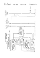
- FIG. 4 is a schematic block diagram illustrating that the holographic and fixed-projection laser scanning subsystems, the package dimensioning/measurement subsystem, package velocity and length measurement subsystem, the package-in-tunnel indication subsystem, the package-out-of-tunnel subsystem, the package weighing-in-motion subsystem the data-element queuing, handling and processing subsystem, the input/output port multiplexing subsystem, and the conveyor belt control subsystem integrated together within the automated tunnel-type package identification and measurement system of the first illustrative embodiment of the present invention;
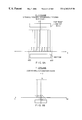
- FIG. 5A is a schematic diagram showing the directions of omni-directional scanning provided in the X-Y plane of the 3-D scanning volume of the tunnel scanning system of the first illustrative embodiment of the present invention, by the Front and Back holographic laser scanning subsystems, and bottom-mounted fixed projection scanning subsystem employed therein;
- FIG. 5B is a schematic diagram showing the direction of omni-directional scanning provided in the Y-Z plane of the 3-D scanning volume of the tunnel scanning system of the first illustrative embodiment, by the bottom-mounted fixed-projection laser scanning subsystem employed therein;
- FIG. 6 is a schematic diagram showing the direction of omni-directional scanning provided in the X-Y plane of the 3-D scanning volume of the tunnel scanning system of the first illustrative embodiment, by the Left Side Front, Left Side Back, Right Side Front and Right Side Back holographic laser scanning subsystems employed therein;
- FIG. 7 is a schematic diagram showing the direction of omni-directional scanning provided in the Y-Z plane of the 3-D scanning volume of the tunnel scanning system of the first illustrative embodiment, by the Front and Back holographic laser scanning subsystems employed therein;
- FIG. 8A is a schematic diagram showing the direction of omni-directional scanning provided in the Y-Z plane of the 3-D scanning volume of the tunnel scanning system of the first illustrative embodiment of the present invention, by the holographic laser scanning subsystems (indicated by R/B Corner #1, R/B Corner #2, L/F Corner #1 and R/B Corner #2) employed therein;
- FIG. 8B is a schematic diagram showing the direction of omni-directional scanning provided in the X-Y plane of the 3-D scanning volume of the tunnel scanning system of the first illustrative embodiment of the present invention, by the holographic laser scanning subsystems (indicated by R/B Corner #1, R/B Corner #2, R/F Corner #1 and R/B Corner #2) employed therein;
- FIG. 9A is a schematic diagram showing the direction of omni-directional scanning provided in the Y-Z plane of the 3-D scanning volume of tunnel scanning system of the first illustrative embodiment of the present invention, by the holographic laser scanning subsystems (indicated by L/B Corner #1, L/B Corner #2, L/F Corner #1 and L/B Corner #2) employed therein;
- FIG. 9B is a schematic diagram showing the direction of omni-directional scanning provided in the X-Y plane of the 3-D scanning volume of tunnel scanning system of the first illustrative embodiment of the present invention, by the holographic laser scanning subsystems (indicated by L/B Corner #1, L/B Corner #2, L/F Corner #1 and L/B Corner #2) employed therein;
- FIG. 10 is a schematic representation of the components on the motherboard and decode processing boards associated with holographic scanning disc employed within the tunnel scanning subsystem of the first illustrative embodiment of the present invention, showing the home-pulse detector and home-offset pulse (HOP) generator on the mother (control) board, and the start-of-facet-sector pulse (SOFSP) generator, digitizer circuitry, decode signal processor and ROM containing relative timing information about each SOFSP in relation to the HOP sent to the decode processing board from the control board of the present invention;
- HOP home-pulse detector and home-offset pulse
- SOFSP start-of-facet-sector pulse
- FIG. 10A is a schematic representation of the start-of-facet-sector pulse (SOFSP) generator employed on each decode board associated with a holographic laser scanning subsystem in the system of the first illustrative embodiment of the present invention;
- SOFSP start-of-facet-sector pulse
- FIG. 10B is a first table containing parameters and information that are used within the SOFP generation module of the SOFSP generator shown in FIG. 10A;
- FIG. 10C is a schematic representation of the operation of the start-of-facet pulse (SOFP) generator employed within each SOFSP generator of the present invention, wherein start of facet pulses are generated within the SOFP generator relative to the home-offset pulse (HOP) received from the HOP generator on the mother/control board associated with each holographic scanning disc;
- SOFP start-of-facet pulse
- HOP home-offset pulse
- FIG. 10D is a second table containing parameters and information that are used within the SOFSP generation module of the SOFSP generator shown in FIG. 10A;
- FIGS. 10 E 1 and 10 E 2 set forth a table containing a set of production rules used within the SOFSP generation module of the SOFSP generator shown in FIG. 10A, to generate start-of-facet-sector pulses therewithin;
- FIG. 10F is a schematic representation of the operation of the start-of-facet-sector pulse (SOFSP) generator of the present invention, wherein start of facet sector pulses (SOFSPs) are generated within the SOFSP generator relative to the home-offset pulse (HOP) received from the HOP generator on the mother/control board associated with each holographic scanning disc;
- SOFSP start-of-facet-sector pulse
- FIGS. 11 (1) and 11 (2) taken together, set forth a schematic diagram of the digitizing circuit shown in FIG. 10, using a pair of dual FIFO memory storage buffers to synchronously track digital scan data and information about the facet-sectors on the optically-encoded holographic scanning disc of FIG. 12 used to generate the laser scanning beam that was used to collect such digital scan data from a bar code symbol on a package transported through the tunnel scanning subsystem of the first illustrative embodiment of the present invention;
- FIG. 11A is a schematic diagram showing in greater detail the digitizing circuit shown in FIG. 10;
- FIGS. 11 B 1 , 11 B 2 and 11 C set forth tables containing parameters and information that are used within the decode processor of the present invention shown in FIG. 11A in order to recover digital count data from time-based facet-sector related information, and generate decoded symbol character data and the minimum and maximum facet sector angles that specify the facet sector on a particular holographic scanning disc used to generate the laser scanning beam/plane that collected the scan data associated with the decoded bar code symbol;
- FIG. 11D is a high level flow chart describing the steps of the process carried out by the decode processor of the present invention shown in FIG. 11A;
- FIG. 12 is a schematic diagram of the holographic scanning disc that contains an optically-encoded home-pulse mark as well as a series of start-of-facet-sector (SOFS) marks about the outer edge thereof for indicating where each facet sector along the disc begins, relative to the home pulse mark;
- SOFS start-of-facet-sector
- FIG. 13A is a schematic representation of the components on the motherboard (i.e. control board) and decode processing boards associated with an optically-encoded holographic scanning disc which can be employed within the tunnel scanning subsystem of the present invention, showing the home-pulse detector and home-offset pulse (HOP) generator on the motherboard, and the start-of-facet-sector pulse (SOFSP) generator, digitizer circuitry, decode signal processor and ROM containing relative timing information about each SOFSP in relation to the HOP sent to the decode processing board from the control board of the present invention;
- HOP home-pulse detector and home-offset pulse
- SOFSP start-of-facet-sector pulse
- FIG. 13B is a schematic representation of the start-of-facet-sector pulse (SOFSP) generator employed on each decode board shown in FIG. 13A;
- SOFSP start-of-facet-sector pulse
- FIG. 13C is a table containing parameters and information that are used within the SOFSP generation module of the SOFSP generator shown in FIG. 13B;
- FIG. 13D is a schematic representation of the operation of the start-of-facet sector pulse (SOFSP) generator shown FIG. 13B, wherein start of facet sector pulses are generated therewithin relative to the home-offset pulse (HOP) received from the HOP generator on the mother/control board associated with each holographic scanning disc;
- SOFSP start-of-facet sector pulse
- HOP home-offset pulse
- FIGS. 14 (1) and 14 (2) taken together, set forth a schematic diagram of the digitizing circuit shown in FIG. 13A using a pair of dual FIFO memory storage buffers to synchronously track digital scan data and information about the facet-sectors on a holographic scanning disc used to generate the laser scanning beam that was used to collected such digital scan data from a bar code symbol on a package transported through the tunnel scanning subsystem hereof;
- FIG. 14A is a schematic diagram showing the digitizing circuit of FIGS. 14 (1) and 14 (2)U in greater detail;
- FIGS. 14 B 1 and 14 B 2 are tables containing parameters and information that are used within the decode processor of the present invention shown in FIG. 13A in order to recover digital count data from time-based facet-sector related information, and generate decoded symbol character data and the minimum and maximum facet sector angles that specify the facet sector on a particular holographic scanning disc used to generate the laser scanning beam/plane that collect the scan data associated with the decoded bar code symbol;
- FIG. 14C is a high level flow chart describing the steps of the process carried out by the decode processor of the present invention shown in FIG. 13A;
- FIG. 14D is a schematic representation of the components on the motherboard and decode processing boards associated with a holographic scanning disc employed within an alternative embodiment of the holographic scanning subsystems in the tunnel scanning subsystem of the first illustrative embodiment of the present invention, showing the home-pulse detector and home-offset pulse (HOP) generator on the mother (control) board, and the start-of-facet-sector pulse (SOFSP) generator, digitizer circuitry, and decode signal processor.
- HOP home-pulse detector and home-offset pulse
- SOFSP start-of-facet-sector pulse
- FIG. 14E is a schematic representation of the start-of-facet-sector pulse (SOFSP) generator employed on each decode board associated with a holographic laser scanning subsystem depicted in FIG. 14D;
- SOFSP start-of-facet-sector pulse
- FIG. 14F is a flow chart describing the operation of the HOP generator on the motherboard associated with each holographic scanning disc, wherein home offset pulses (HOPs) are automatically generated from the HOP generator aboard the motherboard in each holographic laser scanning subsystem independent of the angular velocity of the holographic scanning disc employed therein;
- HOPs home offset pulses
- FIG. 14G is a flow chart describing the operation of the SOFSP generator aboard each decode board, wherein start of facet pulses (SOFPs) are automatically generated within the SOFP generation module relative to the home-offset pulse (HOP) received by the control module in the SOFSP generator independent of the angular velocity of the holographic scanning disc of the subsystem, and wherein start of facet sector pulses (SOFSPs) are automatically generated within the SOFSP generation module relative to SOFPs generated by the SOFP generation module, independent of the angular velocity of the holographic scanning disc of the subsystem;
- SOFPs start of facet pulses
- HOP home-offset pulse
- FIG. 15A is a schematic representation showing the dual-laser based package velocity and measurement subsystem installed in a “direct transmit/receive” configuration at the location of the vertical and horizontal light curtains employed in the package profiling subsystem of the present invention
- FIG. 15 A 1 is a schematic representation of the signals received by the photoreceivers of the dual-laser based package velocity and measurement subsystem shown in FIG. 15;
- FIG. 15 A 2 is a schematic representation of the signals generated by the photoreceiving circuitry and provided as input to the signal processor of the dual-laser based package velocity and measurement subsystem shown in FIG. 15;
- FIG. 15 A 3 is a schematic diagram of circuitry for driving the dual laser diodes used in the dual-laser based package velocity and measurement subsystem of FIG. 15A;
- FIG. 15 A 4 is a schematic diagram of circuitry for conditioning the signals received by the photoreceivers employed in the dual-laser based package velocity and measurement subsystem of FIG. 15A;
- FIG. 15B is a schematic representation showing the dual-laser based package velocity and measurement subsystem installed in a “retro-reflection” configuration at the location of the vertical and horizontal light transmitting/receiving structures employed in the package profiling subsystem of the present invention
- FIG. 15 B 1 is a schematic diagram of electronic circuitry adapted for automatically generating a pair of laser beams at a known space-part distance, towards a retroflective device positioned on the opposite side of the conveyor belt of the system of the first illustrative embodiment of the present invention, and automatically detecting the retroflected beams and processing the same so as to produce signals suitable for computing the length and velocity of a package passing through the transmitted laser beams within the dual-laser based package velocity and measurement subsystem of FIG. 15B;
- FIGS. 15 C through 15 C 2 taken together, set forth a flow chart describing the steps carried out by the signal processor used in the dual-laser based package velocity and measurement subsystems of FIG. 15 and FIG. 15B, so as to compute the velocity (v) and length (L) of the package transported through the laser beams of the dual-laser based package velocity and measurement subsystem hereof;
- FIG. 16 is a perspective view of the automated package identification and measurement system of the present invention, showing the location of the package dimensioning/profiling subsystem (and package-in-tunnel signaling subsystem) in relation thereto and the global coordinate reference system R global symbolically embedded within the structure thereof, as shown;
- FIG. 16A is a schematic representation of the horizontally and vertically arranged light transmitting and receiving structures and subcomponents employed in the package (X-Y) dimensioning/profiling subsystem in the system of the first illustrative embodiment of the present invention
- FIG. 17A is an elevated side view of a pair of packages, arranged in a side-by-side configuration, and about to be transported through the package dimensioning/profiling subsystem of FIG. 16;
- FIG. 17B is a plan view of a pair of packages, arranged in a side-by-side configuration, and about to be transported through the package dimensioning/profiling subsystem of FIG. 16;
- FIG. 17C is an elevated side view of a pair of package, arranged in a side-by-side configuration, and being transported through and thus profiled by the package dimensioning/profiling subsystem of FIG. 16;
- FIG. 18A is an elevated side view of a pair of stacked packages conveyed along the conveyor belt subsystem, wherein one package is being transported through and thus profiled by the package dimensioning/profiling subsystem of FIG. 16, while the other package has not yet been profiled by the subsystem;
- FIG. 18B is an elevated side view of a pair of stacked packages conveyed along the conveyor belt subsystem, wherein both packages are being transported through and thus profiled by the package dimensioning/profiling subsystem of FIG. 16;
- FIG. 18C is an elevated side view of a pair of stacked packages conveyed along the conveyor belt subsystem, wherein one package is being transported through and thus profiled by the package dimensioning/profiling subsystem of FIG. 16, while the other package has already been profiled by the subsystem;
- FIG. 19 is a schematic diagram of an improved third-order finite-impulse-response (FIR) digital filter system that can be used to filter data streams produced from the width and height profiling data channels of the package dimensioning/profiling subsystem of FIG. 16, in order to detect sudden changes in width and height profiles along the conveyor belt, within the context of a method of simultaneous package detection and tracking being carried out on a real-time basis in accordance with the principles of the present invention;
- FIR finite-impulse-response
- FIG. 19A is a flow chart describing the operation of the FIR digital filter system of FIG. 19 and how it detects sudden changes in the width and height data streams produced by the package dimensioning/profiling subsystem of FIG. 16;
- FIG. 19B is a flow chart describing the method of simultaneously detecting “side-by-side” configurations of packages along a conveyor belt using the FIR digital filter system of FIG. 19 to detect sudden changes in the width data streams produced by the package dimensioning/profiling subsystem of FIG. 16;
- FIG. 19C is a flow chart describing the method of simultaneously detecting “stacked” configurations of packages along a conveyor belt using the FIR digital filter of FIG. 19 to detect sudden changes in the height data streams produced by the package dimensioning/profiling subsystem of FIG. 16;
- FIG. 20A is an elevated side schematic view of the in-motion weighing subsystem employed in the system of the first illustrative embodiment of the present invention, wherein the scale and data processing subcomponents thereof are shown arranged about the package dimensioning/profiling subsystem of FIG. 16;
- FIG. 20B is a plan view of the in-motion weighing subsystem shown in FIG. 20A, wherein a moving package is shown being weighed on the scale component as it is transported along the conveyor belt of the system of the first illustrative embodiment;
- FIG. 21 is a schematic diagram of the package-out-of-tunnel signaling subsystem employed in the automated package identification and measuring system of the first illustrative embodiment of the present invention.
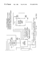
- FIGS. 22 ( 1 ), 22 ( 2 ) and 22 A taken together provide a schematic representation of the data element queuing, handling and processing subsystem of the present invention shown in FIG. 4;
- FIGS. 23 A 1 and 23 A 2 set forth a table of rules used to handle the data elements stored in the system event queue in the data element queuing, handling and processing subsystem of FIGS. 22 ( 1 ) and 22 ( 2 );
- the package surface geometry modeling subsystem i.e. module deployed with the data element queuing, handling and processing subsystem of FIGS. 22 ( 1 ) and 22 ( 2 ), illustrating how each surface of each package (transported through package dimensioning/measuring subsystem and package velocity/length measurement subsystem) is mathematically represented (i.e. modeled) using at least
- FIG. 24A is a table setting forth a preferred procedure for creating a vector-based surface model for each surface of each package transported through the package dimensioning/measuring subsystem and package velocity/length measurement subsystem of the system hereof;
- FIGS. 25 A through 25 A 1 is schematic representation of a diffraction-based geometric optics model, created by the scan beam geometry modeling subsystem (i.e. module) of FIGS. 22 ( 1 ) and 22 ( 2 ), for the propagation of the laser scanning beam (ray) emanating from a particular point on the facet, towards its point of reflection on the corresponding beam folding mirror, towards to the focal plane determined by the focal length of the facet, created within the scan beam geometry modeling module shown in FIGS. 22 ( 1 ) and 22 ( 2 );
- the scan beam geometry modeling subsystem i.e. module of FIGS. 22 ( 1 ) and 22 ( 2 )
- FIGS. 25 B 1 through 25 B 3 set forth a table of parameters used to construct the diffraction-based geometric optics model of the scanning facet and laser scanning beam shown in FIGS. 25 A and 25 A 1 ;
- FIGS. 25 C 1 through 25 C 2 comprise a table setting forth mathematical expressions used to construct the model shown in FIGS. 25 B 1 through 2533 ;
- FIG. 26 is a schematic representation of the laser scanning disc shown in FIGS. 25 A and 25 A 1 , labeled with particular parameters associated with the diffraction-based geometric optics model of FIGS. 25 A and 25 A 1 ;
- FIG. 27 is a table setting forth a preferred procedure for creating a vector-based ray model for laser scanning beams which have been produced by a holographic laser scanning subsystem of the system hereof, that may have collected the scan data associated with a decoded bar code symbol read thereby within the tunnel scanning subsystem;
- FIG. 29 is a schematic representation graphically illustrating how a vector-based model created within a local scanner coordinate reference frame R localscannerj can be converted into a corresponding vector-based model created within the global scanner coordinate reference frame R global using homogeneous transformations;
- FIG. 30 is a schematic representation graphically illustrating how a vector-based package surface model created within the global coordinate reference frame R global at the “package profiling position” can be converted into a corresponding vector-based package surface model created within the global scanner coordinate reference frame R global at the “scanning position” within the tunnel using homogeneous transformations, and how the package travel distance (d) between the package profiling and scanning positions is computed using the package velocity (v) and the difference in time indicated by the time stamps placed on the package data element and scan beam data element matched thereto during each scan beam/package surface intersection determination carried out within the data element queuing, handling and processing subsystem of FIGS. 22 ( 1 ), 22 ( 2 ) and 22 A;
- FIGS. 31A and 31B taken together, provide a procedure for determining whether the scan beam (rays) associated with a particular scan beam data element produced by a holographic scanning subsystem intersects with any surface on the package that has been scanned at a particular scanning position, and thus whether to correlate a particular package identification data element with particular package measurement data element acquired by the system;
- FIGS. 32A and 32B taken together, provide a procedure for determining whether the scanning surface associated with a particular scan beam data element produced by a non-holographic (e.g. polygon-based) bottom-located scanning subsystem intersects with any surface on the package that has been scanned at a particular scanning position, and thus whether to correlate a particular package identification data element with particular package measurement data element acquired by the system;
- a non-holographic (e.g. polygon-based) bottom-located scanning subsystem intersects with any surface on the package that has been scanned at a particular scanning position, and thus whether to correlate a particular package identification data element with particular package measurement data element acquired by the system;
- FIG. 33 is a perspective view of a “dual-lane” automated tunnel-type laser scanning package identification and weighing system constructed in accordance with the second illustrated embodiment of the present invention.
- FIG. 34 is a schematic block diagram illustrating the holographic laser scanning subsystems, the package-in-tunnel indication subsystem, the package velocity detection subsystem, the package-out-of-tunnel subsystem, the package weighing-in-motion subsystem, the data-element queuing, handling and processing subsystem, the input/output port multiplexing subsystem, and the conveyor belt control subsystem;
- FIG. 35 is a schematic representation of the laser scanning pattern projected from each disc in the dual-disc holographic laser scanning subsystem employed in the tunnel-type scanning system of the second illustrative embodiment of the present invention.
- FIG. 36 is a plan view of a dual-disc holographic laser scanning subsystem mounted over the conveyor belt of the system shown in FIG. 33;
- FIG. 37 is a schematic representation of each holographic laser scanning disc employed in the laser scanning subsystem of the present invention.
- FIG. 38 is a table setting forth the design parameters used to construct each holographic disc within the dual-disc holographic scanning subsystem employed in the tunnel scanning system of the second illustrative embodiment;
- FIGS. 39A through 39C taken together, show the subcomponents configured together on the analog signal processing boards, decode signal processing boards and within the housing of the single-disc holographic laser scanning subsystems of the second illustrative embodiment of the present invention
- FIGS. 40A through 40C taken together, sets forth a flow chart describing the computational process used by the conveyor belt velocity detection subsystem of FIG. 33, to compute the velocity of the conveyor belt of the system of the second illustrative embodiment of the present invention
- FIGS. 41A and 41B, taken together, set forth a taken together provide a schematic representation of the data element queuing, handling and processing subsystem employed in the system of the second illustrative embodiment of the present invention, illustrated in FIG. 33;
- FIGS. 42A and 42B set forth a table of rules used to handle the data elements stored in the system event queue in the data element queuing, handling and processing subsystem of FIGS. 41A and 41B;
- FIG. 43 is a schematic representation of the system and method used herein to create vector-based models of each package location region within the tunnel scanning system of the second illustrative embodiment
- FIGS. 44A and 44B taken together, set forth a flow chart setting forth a preferred procedure for creating a vector-based model for each package location region within the tunnel scanning system of the second illustrative embodiment
- FIG. 45 is a schematic representation graphically illustrating how a vector-based scanning beam model created within a local scanner coordinate reference frame R localscannerj can be converted into a corresponding vector-based model created within the global scanner coordinate reference frame R global using homogeneous transformations;
- FIG. 46 is a flow chart setting forth a preferred procedure for determining whether the scan beam (rays) associated with a particular scan beam data element produced by a holographic scanning subsystem within the system of FIG. 33 intersects with the package location region associated with the package scanned at the scanning position associated with the scan beam data element, and thus whether to correlate a particular package identification data element with a particular package measurement data element or like token acquired by the system;
- FIG. 47 is a perspective view of an automated tunnel-type laser scanning package identification and weighing system constructed in accordance with the third illustrated embodiment of the present invention, wherein multiple packages, arranged in stacked and/or side-by-side configurations, are transported along a high speed conveyor belt, dimensioned, weighed and identified in a fully automated manner without human intervention;
- FIG. 48 is schematic block diagram of the system of FIG. 47, showing the subsystem structure thereof as comprising a scanning tunnel including holographic and non-holographic laser scanning subsystems, a first simultaneous multiple-package detection and dimensioning subsystem installed on the input side of the tunnel scanning subsystem, a second simultaneous multiple-package detection and dimensioning subsystem installed on the output side of the tunnel scanning subsystem, a package/belt velocity detection subsystem, a package weighing-in-motion subsystem, a data-element queuing, handling and processing subsystem, an input/output (I/O) subsystem, a conveyor belt subsystem, and a master clock for establishing a global time reference when time-stamping data elements generated throughout the system;
- a scanning tunnel including holographic and non-holographic laser scanning subsystems, a first simultaneous multiple-package detection and dimensioning subsystem installed on the input side of the tunnel scanning subsystem, a second simultaneous multiple-package detection and dimensioning subsystem installed on the output side of the tunnel scanning subsystem,
- FIG. 49 A 1 and 49 A 2 taken together, set forth a schematic representation of the first simultaneous multiple-package detection and dimensioning subsystem installed on the input side of the tunnel scanning subsystem, showing its various constituent subcomponents;
- FIG. 49A is a schematic representation of the height profile data analyzer employed in the subsystem of FIG. 49, comprising a data controller, time-stamping module, a height profile data element queue, a height profile data analyzer, and a plurality of moving package tracking queues assigned to different spatial regions above the conveyor belt of the system located on the input side of the tunnel scanning subsystem;
- FIG. 49B is a schematic block diagram of the laser scanning mechanism employed in the simultaneous multiple-package detection and dimensioning subsystem shown in FIG. 49;
- FIG. 50 is a schematic representation of the second simultaneous multiple-package detection and dimensioning subsystem installed on the output side of the tunnel scanning subsystem, showing its various constituent subcomponents;
- FIGS. 50 A 1 and 50 A 2 taken together, set forth a schematic representation of the height profile data analyzer employed in the subsystem of FIG. 50, comprising a data controller, time-stamping module, a height profile data element queue, a height profile data analyzer, and a plurality of moving package tracking queues assigned to different spatial regions above the conveyor belt of the system located on the output side of the tunnel scanning subsystem;
- FIG. 50B is a schematic block diagram of the laser scanning mechanism employed in the simultaneous multiple-package detection and dimensioning subsystem shown in FIG. 50;
- FIGS. 51 A 1 , 51 A 2 and 51 A taken together, provide a schematic representation of the data element queuing, handling and processing subsystem of the present invention shown in FIGS. 47 and 48;
- FIGS. 52A and 52B set forth a table of rules used to handle the data elements stored in the scan beam data element (SBDE) queue in the data element queuing, handling and processing subsystem of FIG. 51;
- SBDE scan beam data element
- the package surface geometry modeling subsystem i.e. module deployed with the data element queuing, handling and processing subsystem of FIGS. 49 and 49A
- FIG. 53B is a table setting forth a preferred procedure for creating a vector-based surface model for each surface of each package transported through the package detection and dimensioning subsystem of the system hereof;
- FIG. 54 is a table setting forth a preferred procedure for creating a vector-based ray model for laser scanning beams which have been produced by a holographic laser scanning subsystem of the system hereof, that may have collected the scan data associated with a decoded bar code symbol read thereby within the tunnel scanning subsystem;
- FIG. 56 is a schematic representation graphically illustrating how a vector-based model created within a local scanner coordinate reference frame R localscannerj can be converted into a corresponding vector-based model created within the global scanner coordinate reference frame R global using homogeneous transformations;
- FIG. 57 is a schematic representation graphically illustrating how a vector-based package surface model created within the global coordinate reference frame R global at the “package profiling position” can be converted into a corresponding vector-based package surface model created within the global scanner coordinate reference frame R global at the “scanning position” within the tunnel using homogeneous transformations, and how the package travel distance (d) between the package profiling and scanning positions is computed using the package velocity (v) and the difference in time indicated by the time stamps placed on the package data element and scan beam data element matched thereto during each scan beam/package surface intersection determination carried out within the data element queuing, handling and processing subsystem of FIGS. 51 and 51A;
- FIGS. 58A and 58B taken together, provide a procedure for determining whether the scan beam (rays) associated with a particular scan beam data element produced by a holographic scanning subsystem intersects with any surface on the package that has been scanned at a particular scanning position, and thus whether to correlate a particular package identification data element with particular package measurement data element acquired by the system;
- FIGS 59 A and 59 B taken together, provide a procedure for determining whether the scanning surface associated with a particular scan beam data element produced by a non-holographic (e.g. polygon-based) bottom-located scanning subsystem intersects with any surface on the package that has been scanned at a particular scanning position, and thus whether to correlate a particular package identification data element with particular package measurement data element acquired by the system.
- a non-holographic (e.g. polygon-based) bottom-located scanning subsystem intersects with any surface on the package that has been scanned at a particular scanning position, and thus whether to correlate a particular package identification data element with particular package measurement data element acquired by the system.
- FIG. 1 there is shown an automated tunnel-type laser scanning package identification and measuring (e.g. dimensioning and weighing) system designed to meet the needs of demanding customers, such as the United States Postal Service (USPS), which requires “hands-free” bar code (or code symbol) scanning of at least six-sided packages, wherein the label containing the code symbol to be read could be positioned in any orientation on any one of the six or more sides of the box or container structure.
- USPS United States Postal Service
- the term “hands-free” shall mean scanning of bar codes on boxes or parcels that are travelling past the scanners in only one direction on some sort of conveyor system.
- the package should be singulated in a conventional manner.
- the automated tunnel scanning system of the first illustrative embodiment indicated by reference numeral 1 comprises an integration of subsystems, namely: a high-speed package conveyor system 300 having a conveyor belt 302 A and 302 B having a width of at least 30 inches to support one or more package transport lanes along the conveyor belt; a tunnel scanning subsystem 100 including an arrangement of holographic and non-holographic laser scanning bar code symbol reading subsystems 101 through 117 supported overhead and below the conveyor belt by a support frame 150 so as to produce a truly 3-D omnidirectional scanning volume above the conveyor belt, for scanning bar codes on packages transported therethrough independent of the package or bar code orientation; a package velocity and length measurement subsystem 400 ; a package-in-the-tunnel indication subsystem 500 realized as a 2-D light sensing structure mounted along the conveyor belt, on the input side of the tunnel, for automatically detecting the presence of each package moving into the scanning tunnel; a package (x-y) dimensioning subsystem 600 , employing the 2-D light sensing structure
- the tunnel scanning system of the first illustrative embodiment 1 comprises an arrangement of laser scanning subsystems (i.e. scanners) 101 through 117 which, by virtue of their placement, relative to the conveyor belt subsystem 300 , essentially form a “tunnel” scanning subsystem over and about the conveyor belt of the conveyor subsystem.
- laser scanning subsystems i.e. scanners
- this type of code symbol scanning system is known as a “tunnel scanning system” by those skilled in the art.
- the tunnel scanning system of the illustrative embodiment shown in great detail in the drawings, has been designed and constructed to meet a specific set of customer-defined scanning parameters.
- the bar code label could be on any one side of a box having six sides.
- the bar code label could be in any orientation.
- the object bearing the bar code label to be read would be moving past the scanners of the on a conveyor belt travelling at speeds in excess of 400 feet per second.
- the conveyor belt belts 302 A and 302 B are moving at 520 feet per second.
- the types of codes to be read include such codes as Code 39, Code 128 and others.
- the aspect ratio of the bar codes to be read is on the order of 10 mils and up.
- the tunnel scanning system of the present invention can be used in various types of applications, such as for example, where the bar codes are read to determine (a) identification of incoming packages, (b) identification of outgoing packages, and (c) sortation of outgoing packages.
- the information derived from the bar code will be used not only to identify the package, but also to direct the package along a particular path using deflectors, routers and other instruments well known in the package and parcel handling art.
- the volume to be scanned within the tunneling subsystem is approximately: 1 meter wide (i.e. the width of the conveyor belt); ten feet long; and 1 meter tall (i.e. the height of the tallest possible box going through).
- the 3-D scanning volume of the tunnel scanning system measured with respect to the surface of the conveyor belt, begins at the surface of the conveyor belt in order to scan flat items (such as envelopes), and extends up approximately 1 meter (“h) above the surface of the conveyor belt subsystem.
- sixteen holographic laser scanning subsystems 101 through 116 are mounted on a lightweight scanner support framework 4 , at positions specified in Tunnel Scanner Positioning Data Table shown in FIG. 2 C.
- the terms e.g. “Top/Front”, Top/Back”, etc.
- the one fixed-projection scanner subsystem 117 is mounted between the gap provided between the first and second conveyor platforms comprising the conveyor subsystem 300 of the tunnel scanning subsystem 100 .
- Each of the holographic scanners (denoted in R/I Corner #1, R/I Corner #2, R/B Corner #1, R/B Corner #2, L/F Corner #1, L/F Corner #2, L/B Corner #1, L/B Corner #2,) mounted within the corners of the scanner support framework are single-disc holographic scanning subsystems, having five focal planes, formed using six laser scanning stations, each of which includes a VLD, a beam folding mirror, parabolic light collection mirror, signal processing circuit boards and the like, are designed and constructed using the methods detailed in Applicant's copending application Ser. Nos. 08/949,915 filed Oct. 14, 1997; 08/854,832 filed May 12, 1997; 08/886,806 filed Apr.
- the design parameters for the twenty facet holographic scanning disc shown in FIG. 3 A 4 , and the supporting subsystem used therewith, are set forth in the Table of FIGS. 3 A 5 A through 3 A 5 C. Notably, the design parameters set forth in the table of FIGS. 3 A 5 A through 3 A 5 C are defined in detail in the above-referenced US Patent Applications.
- the scanning pattern projected on the middle (third) focal/scanning plane of each such single-disc holographic scanning subsystem is shown in FIG. 3 A 6 .
- FIGS. 5A through 9B The various omnidirectional scanning directions provided for within the 3-D scanning volume of the tunnel-scanning system of the present invention are schematically illustrated, in FIGS. 5A through 9B. These illustrations indicate how each of the laser scanning subsystems within the tunnel scanning systems contribute to produce the truly omnidirectional scanning performance attained by the tunnel scanner hereof.
- the two triple-disc holographic scanners are mounted above the conveyor belt by way of the scanner support framework.
- the four triple-disc holographic scanners (denoted as Left Side Front, Left Side Back, Right Side Front and Right Side Back) are mounted on the left and right sides of the scanner support framework.
- Each of these triple-disc holographic scanning subsystems is shown in greater detail in FIGS. 3 B 1 through 3 B 8 .
- Each of these holographic scanning subsystems has five focal planes, formed using three sets (groups) of six laser scanning stations, arranged about a twenty-facet scanning disc.
- Each laser scanning station about the scanning disc includes a VLD, a beam folding mirror, parabolic light collection mirror, signal processing circuit boards and the like.
- Each holographic laser scanning subsystem within these triple-disc scanners are designed and constructed using the methods detailed in Applicant's copending application Ser. Nos. 08/949,915 filed Oct. 14, 1997, now U.S. Pat. No. 6,158,659; 08/854,832 filed May 12, 1997; 08/886,806 filed Apr. 22, 1997; 08/726,522 filed Oct. 7, 1996; and 08/573,949 filed Dec. 18, 1995, each incorporated herein by reference.
- the design parameters for each twenty facet holographic scanning disc shown in FIG. 3 B 2 , and the supporting subsystem used therewith, are set forth in the Table of FIGS. 3 B 3 A and 3 B 3 B. Notably, the design parameters set forth in the table of FIGS. 3 B 3 A and 3 B 3 B are defined in detail in the above-referenced US Patent Applications.
- the scanning pattern projected on the middle (third) focal/scanning plane of each such triple-disc holographic scanning subsystem is shown in FIG. 3 B 8 .
- the two triple-disc holographic scanners (denoted as Front and Back) are mounted above the conveyor belt by way of the scanner support framework.
- Each of these triple-disc holographic scanning subsystems is shown in greater detail in FIGS. 3 C 1 and 3 C 2 .
- Each of these holographic scanning subsystems has five focal planes, formed using three sets (groups) of six laser scanning stations, arranged about a twenty-facet scanning disc.
- Each laser scanning station about the scanning disc has a VLD, a beam folding mirror, parabolic light collection mirror, signal processing circuit boards and the like.
- Each holographic laser scanning subsystem within these triple-disc scanners are designed and constructed using the methods detailed in Applicant's copending application Ser. Nos. 08/949,915 filed Oct.
- the bottom-mounted fixed projection scanner (denoted as Bottom) employed in the tunnel scanning system hereof is shown in greater detail in FIGS, 3 D 1 through 3 D 7 .
- the bottom-mounted scanner comprises eight fixed-projection laser scanning subsystems 6 , shown in FIG. 3 D 2 , that are mounted along optical bench 7 shown in FIG. 3 D 1 .
- Each fixed projection scanning subsystem 6 comprises: four stationary mirrors 7 arranged about a central reference plane passing along the longitudinal extent of the optical bench 8 of the subsystem; and eight-sided motor driven polygon scanning element 10 mounted closely to the nested array of mirrors 8 ; a light collecting mirror 9 mounted above the nested array along the central reference plane; a laser diode 11 for producing a laser beam which is passed through collecting mirror 9 and strikes the polygon 10 ; and a photodetector 12 , mounted above the polygon scanning element, for detecting reflected laser light in a manner well known in the art to produce scan data signals for signal processing.
- FIG. 3 D 4 and 3 D 5 the partial scan pattern produced by individual stationary mirrors in each subsystem 6 are shown.
- the complete pattern generated by each subsystem 6 is shown in FIG. 3 D 6 .
- the composite omnidirectional scanning pattern generated by the eight subsystems 6 working together in the bottom scanner is shown in FIG. 3 D 7 .
- each holographic laser scanning unit of the present invention comprises a number of system components, many of which are realized on a control (i.e. motherboard) board 200 , a plurality (e.g. six) analog signal processing boards 201 A- 201 -F, and six digital signal processing boards 202 A- 202 F.
- a control board 200 i.e. motherboard
- a plurality (e.g. six) analog signal processing boards 201 A- 201 -F e.g. six) analog signal processing boards 201 A- 201 -F
- six digital signal processing boards 202 A- 202 F digital signal processing boards
- each analog scan data signal processing board 201 A- 201 F has the following components mounted thereon: an associated photodetector 215 A (through 215 F) (e.g. a silicon photocell) for detection of analog scan data signals as described; and an analog signal processing circuit 235 A (through 235 F) for processing detected analog scan data signals.
- an associated photodetector 215 A e.g. a silicon photocell
- an analog signal processing circuit 235 A through 235 F for processing detected analog scan data signals.
- each photodetector 215 A through 215 F is realized as an opto-electronic device and each analog signal processing circuit 235 A aboard the analog signal processing board is realized as an Application Specific Integrated Circuit (ASIC) chip.
- ASIC Application Specific Integrated Circuit
- These chips are suitably mounted onto a small printed circuit (PC) board, along with electrical connectors which allow for interfacing with other boards within the scanner housing. With all of its components mounted thereon, each PC board is suitably fastened to the photodetector support frame 220 , along its respective central reference frame, as shown in FIG. 3 A 2 .
- the optical scan data signal D 0 focused onto the photodetector ( 215 A) during laser scanning operations is produced by light rays of a particular polarization state (e.g. S polarization state) associated with a diffracted laser beam being scanned across a light reflective surface (e.g. the bars and spaces of a bar code symbol) and scattering thereoff.
- a particular polarization state e.g. S polarization state
- the polarization state distribution of the scattered light rays is altered when the scanned surface exhibits diffuse reflective characteristics. Thereafter, a portion of the scattered light rays are reflected along the same outgoing light ray paths toward the holographic facet which produced the scanned laser beam.
- each photodetector is to detect variations in the amplitude (i.e. intensity) of optical scan data signal D 0 , and produce in response thereto an electrical analog scan data signal D 1 which corresponds to such intensity variations.
- the amplitude variations of electrical analog scan data signal D 1 will linearly correspond to the light reflection characteristics of the scanned surface (e.g. the scanned bar code symbol).
- the function of the analog signal processing circuitry is to band-pass filter and preamplify the electrical analog scan data signal D 1 , in order to improve the SNR of the output signal.
- each digital scan data signal processing board 202 A through 202 F is constructed in substantially the same manner.
- the following devices are provided: an analog-to-digital (A/D) conversion circuit 238 A through 238 F realized as a first application specific integrated circuit (ASIC) chip; a programmable digitizing circuit 239 A through 239 F realized as a second ASIC chip; a start-of-facet-sector pulse (SOFSP) generator 236 A through 236 F realized as a programmable IC chip, for generating SOFSPs relative to home-offset pulses (HOP) generated by a HOP generator circuit on the mother board 200 , and received by the SOFSP generator; an EPROM 237 A through 237 F for storing parameters and information represented in the tables of FIGS.
- A/D analog-to-digital
- ASIC application specific integrated circuit
- SOFSP start-of-facet-sector pulse
- HOP home-offset pulses
- a programmed decode computer 240 A through 240 F is realized as a microprocessor and associated program and data storage memory and system buses, for carrying out symbol decoding operations and recovery of SOFSPs from the digitizer circuit 239 A in a synchronous, real-time manner as will be described in greater detail hereinafter.
- the ASIC chips, the microprocessor, its associated memory and systems buses are all mounted on a single printed circuit (PC) board, using suitable electrical connectors, in a manner well known in the art.
- the function of the A/D conversion circuit ( 238 A) is to perform a simple thresholding function in order to convert the electrical analog scan data signal D 1 into a corresponding digital scan data signal D 2 having first and second (i.e. binary) signal levels which correspond to the bars and spaces of the bar code symbol being scanned.
- the digital scan data signal D 2 appears as a pulse-width modulated type signal as the first and second signal levels thereof vary in proportion to the width of bars and spaces in the scanned bar code symbol.
- the function of the programmable digitizing circuit 239 A of the present invention is two-fold: (1) to convert the digital scan data signal D 2 , associated with each scanned bar code symbol, into a corresponding sequence of digital words (i.e. a sequence of digital count values) D 3 representative of package identification (I.D.) data; and (2) to correlate with the digital count values, time-based (or position-based) information about the facet sector on the scanning disc that generated the sequence digital count data (corresponding to a scanline or portion thereof) that was used to read the decoded bar code symbol on the package scanned in the scanning tunnel.
- each digital word represents the time length duration of first or second signal level in the corresponding digital scan data signal D 2 .
- the digital count values are in a suitable digital format for use in carrying out various symbol decoding operations which, like the scanning pattern and volume of the present invention, will be determined primarily by the particular scanning application at hand.
- U.S. Pat. No. 5,343,027 to Knowles incorporated herein by reference, as it provides technical details regarding the design and construction of microelectronic digitizing circuits suitable for use in the holographic laser scanner of the present invention.
- the each programmed decode computer ( 240 A through 240 F) of the present invention has two primary functions: (1) to receive each digital word sequence D 3 produced from its respective digitizing circuit 239 A through 239 F, and subject it to one or more bar code symbol decoding algorithms in order to determine which bar code symbol is indicated (i.e. represented) by the digital word sequence D 3 , originally derived from corresponding scan data signal D 1 detected by the photodetector associated with the decode computer; and (2) to generate a specification for the laser scanning beam (or plane-sector) that was used to collect the scan data underlying the decode bar code symbol.
- the specification for the laser scanning beam is expressed as the minimum and maximum facet angles delimited by the facet sector involved in the scanning of the decoded bar code symbol. Such minimum and maximum facet angles are indicated in the last column of the table shown in FIG. 11 C.
- the second function of the programmed decode processor 240 A through 240 F is described in greater detail in FIGS. 11C and 11D.
- the first function of the programmed decode computer 240 A hereof is to receive each digital word sequence D 3 produced from the digitizing circuit 239 A, and subject it to one or more pattern recognition algorithms (e.g. character recognition algorithms) in order to determine which pattern is indicated by the digital word sequence) D 3 .
- pattern recognition algorithms e.g. character recognition algorithms
- scanned code symbols can be any one of a number of symbologies
- a bar code symbol decoding algorithm with auto-discrimination capabilities can be used in a manner known in the art.
- the control board 200 comprises a number of components mounted on a small PC board, namely: a programmed microprocessor 442 with a system bus and associated program and data storage memory, for controlling the system operation of the holographic laser scanner and performing other auxiliary functions; first, second, third, forth, fifth and sixth serial data channels 243 A through 243 F, for receiving serial data input from the programmable decode computers 420 A through 240 F; an input/output (I/O) interface circuit 248 for interfacing with and transmitting symbol character data and other information to data management computer system 900 ; a home pulse detector 245 realized as the electronic circuit shown in FIG.
- a programmed microprocessor 442 with a system bus and associated program and data storage memory, for controlling the system operation of the holographic laser scanner and performing other auxiliary functions
- first, second, third, forth, fifth and sixth serial data channels 243 A through 243 F for receiving serial data input from the programmable decode computers 420 A through 240 F
- each serial data channel 243 A through 243 F is realized as an RS232 port, although it is understood that other structures may be used to realize the function performed thereby.
- the programmed control computer 242 also produces motor control signals, and laser control signals during system operation. These control signals are received as input by a power supply circuit 252 realized on the power supply PC board. Other input signals to the power supply circuit 252 include a 900 Volt, 60 Hz line voltage signal from a standard power distribution circuit. On the basis of the received input signals, the power supply circuit produces as output, (1) laser source enable signals to drive VLDs 253 A, 253 B and 253 C, respectively, and (2) a motor enable signal in order to drive the scanning disc motor 211 coupled to holographic scanning disc 130 .
- a first method for determining the position of the laser scanning beam in the holographic laser scanning subsystems having constant scanning motor speed, and synchronously encoding facet sector information with digital count data in the digitizer circuit of each decode board.
- this method involves optically encoding the “home pulse mark/gap” along the edge of the holographic scanning disc, and upon detecting the same, generating home offset pulses (HOPs) which are used to automatically generate the start of each facet pulse (SOFPs), and the SOFPs in turn are used to automatically generate the start-of-facet-sector pulses (SOFSPs) aboard each decode board.
- HOPs home offset pulses
- SOFPs start-of-facet-sector pulses
- each home offset pulse produced from HOP generating circuit 244 is provided to the SOFSP generator 236 A through 236 F on the decode processing board.
- the home pulse gap on the scanning disc 130 is starting to pass through the laser beam directed therethrough at the scanning station associated with the decode signal processing board.
- timing information stored in the tables shown in these figures is used by the SOFSP generator 236 A to generate a set of SOFSPs in response to the received HOP pulse during each revolution of the scanning disc.
- each SOFSP generator 236 A through 236 B comprises: a clock 260 for producing clock pulses (e.g. having a pulse duration of about 4 microseconds); a SOFP generation module 261 for generating SOFPs using the table of FIG. 10B in accordance with the process depicted in FIG. 10C; a SOFSP generation module 262 for generating SOFSPs using the table of FIG. 10 D and production rules set forth in FIGS. 10 E 1 and 10 E 2 , in accordance with the process depicted in FIG.
- control module 263 for controlling the SOFP generator 261 and the SOFSP generator 262 , and resetting the clock 260 upon each detection of a new HOP from the HOP generator on the mother control board 200 associated with the holographic scanning unit.
- the digitizer circuit 239 A of the present invention comprises a number of subcomponents.
- a scan data input circuit 322 is provided for receiving digital scan data signal D 2 .
- a clock input 132 is provided from an external fixed frequency source 313 , e.g., a 40 MHz crystal, or another external clock 315 to produce a pulse train.
- the output of the clock input circuit 312 is provided to the clock divider circuitry 314 .
- That circuit 314 includes dividers for successively dividing the frequency of the clock pulses by a factor of two to produce a plurality of clock frequencies, as will be described in detail later.
- This plurality of clock signals is provided to a clock multiplexer 316 . As shown in FIG.
- the 40 MHz clock input signal is also provided directly to the clock multiplexer 316 .
- the clock multiplexer 316 selects the desired output frequencies for the device based upon control signals received from clock control circuitry in the programmable processor 240 A and in associated circuitry.
- the output of the clock multiplexer 316 comprises an S clock signal which provides the basic timing for the digitizer circuit 239 A, as well as the input to digital counters.
- the processing of the input (bar code) scan data D 2 is provided from signal processor 238 A.
- the scanner input circuit 322 provides output signals which represent the detected bar code signal to be processed and are provided to the transition and sign detecting circuit 324 .
- That circuit detects the transition from a bar to a space or a space to a bar from the input signals provided thereto, and also determines whether the symbol occurring before the transition is a bar or a space.
- the transition and sign detector 324 provides a signal bearing the “sign: information (referred to as the “SIGN” signal) which is provided to multiplexer 342 , and thus a primary first-in, first-out (FIFO) memory which serves as the input of programmable processor 240 A.
- the transition and sign circuit 324 also provides a signal to the sequencing means 328 to commence operation of the sequencing circuit 328 .
- the sequencing circuit 328 sequences the digitizer circuit through a predetermined number of steps which begin at the occurrence of each symbol transition and which will be described in detail later.
- Sequencing circuit 328 provides a FIFO write signal to the FIFO input of primary FIFO 340 and the auxiliary FIFO 341 , at the proper time to enable it to accept data thereinto.
- the sequencing circuit 328 provides input signals to digitizing counting circuit 330 so that the starting and stopping of the counters, occurring with the detection of each transition, is properly sequenced.
- the counting circuit 330 also receives an input signal from the clock multiplexer 316 (S Clock). This signal runs the counters at the selected rate when they are enabled by the sequencing means 328 .
- the clock multiplexer 316 , the sequencer circuit 328 and the counting circuit 330 each supply signals to the interface circuit 333 which enables it to properly pass the digitized count data to the primary and auxiliary FIFOs 340 and 341 , via multiplexer 342 , as shown in FIGS. 11 and 11A.
- the clock multiplexer 316 is arranged to provide two banks of available frequencies for the device to use, namely, an upper and a lower bank. The selection of frequencies from the upper bank or the lower bank is determined by a frequency bank switching circuit 362 .
- the frequency bank switching circuit 362 also provides an input to an array reset 38 which provides a signal to reset the clock divider 314 on command.
- the clock divider circuitry 314 also generates a TEST reset signal by inverting the array reset signal.
- the TEST reset signal resets the remainder of the circuit 239 A.
- the command which initiates this reset condition is normally generated by a testing device (not shown) connected to device 239 A and used to test it upon its fabrication.
- digital count data or a string of zeros are written into the primary FIFO using multiplexer 342 and write enable signals generated by the sequencing circuit 238 .
- the SOFP marker i.e. string of zeros
- digital count data or a string of zeros are written into the auxiliary FIFO 341 using multiplexer 342 and write enable signals generated by the sequencing circuit 238 .
- the SOFSP marker i.e.
- the decoder 240 A is allowed to decode process the scan count data in the FIFOs, as well as determine which facet sector produced the laser scanning beam.
- the later function is carried out using the tables set forth in FIGS. 11 B 1 through 11 C and the method described in the flow chart of FIG. 11 D. As shown in FIG.
- the output of the 240 A is a scan beam data element comprising the package ID data, the scanner number (SN), the laser scanning station number (SSN), facet number (FN) and minimum and maximum facet angles subtending the facet sector involved in generating the laser beam used to read the decoded bar code symbol representative of the package ID data. Additional details concerning the design and construction of digitizer circuit ( 239 A) can be found in Applicant's U.S. Pat. No. 5,343,027 incorporated herein by reference in its entirety.
- FIGS. 12A through 14C an alternative method is shown for determining the position of the laser scanning beam holographic laser scanning subsystems under constant scanning motor speed and synchronously encoding facet section information with digital count data in the digitizer circuit of each decode board.
- This method involves optically encoding the start of each facet sector (SFS) mark along the outer edge of the holographic scanning disc 130 , as shown in FIG. 12 A.
- This optical encoding process can be carried out when mastering the scanning disc using a masking pattern during laser exposure.
- the home pulse gap sensing module described above can be used to detect the home pulse gap as well as the SFS marks along the edge of the scanning disc.
- the home gap generates a home pulse while the SFS marks generate a series of SOFSPs during each revolution of the scanning disc.
- the home pulse is detected on the home pulse detection circuit on the motherboard and is used to generate HOPs as in the case described above.
- the HOPs are transmitted to each decode board where they are used to reference (i.e. count) how many SOFSPs have been counted since the received HOP, and thus determine which facet sector the laser beam is passing through as the scanning disc as it rotates.
- Digital counts representative of each SOFSP are synchronously generated by the SOFSP generator aboard each decode board and are loaded into the auxiliary FIFO 341 , while correlated digital count scan data is loaded into both the primary and auxiliary FIFOs in a manner similar to that described above.
- the decode processor uses the information in the tables of FIGS. 13C and 13D to determine which SOFSP counts correspond to which minimum and maximum facet angles in accordance with the decode processing method of the present invention described in FIG. 12 E.
- the advantage of this method is that it is expected to be less sensitive to variations in angular velocity of the scanning disc.
- FIGS. 14D through 14G a novel system and method are illustrated for accurately determining the position of laser scanning beams in holographic laser scanning subsystems under varying scanning disc motor speed conditions.
- a holographic scanning disc having a home pulse mark or gap as shown in FIG. 3 B 2 can be used to generate the required laser scanning pattern.
- each holographic scanning disc is provided with a home pulse sensing module 251 and home pulse detection circuit 245 ′′ as shown in FIG. 14 D.
- a home pulse (HP) is automatically generated from the home pulse detection circuit 245 ′′.
- a set of home offset pulses (HOPs) are sequentially produced from HOP generation circuit 244 in accordance with the process depicted in FIGS. 14F and 14G.
- the number of HOPs produced in response to each detected HP is equal to the number of laser scanning stations (i.e. scanning modules), N, arranged about the laser scanning disc. As shown in FIGS.
- each generated HOP is provided to the SOFSP generator ( 236 A′′ through 236 F′′) on the decode processing board ( 202 A through 202 F) associated with the HOP.
- the home pulse mark or gap on the scanning disc 130 is then starting to pass through the laser beam directed therethrough at the laser scanning station associated with the decode signal processing board.
- the SOFSP generation module 261 ′′ within each SOFSP generation circuit 236 A′′ through 236 F′′ generates a set of start of facet pulses (SOFPs) relative to the HOP, and also a set of start of facet sector pulses (SOFSPs) relative to each SOFSP.
- SOFPs start of facet pulses
- SOFSPs start of facet sector pulses
- SOFP and SOFSP (referenced from the HOP) to be generated by each SOFSP generation circuit 236 A′′ through 236 F′′ and provided to the digitizer circuit 239 A through 239 F so that the SOFP and SOFSP data can be correlated with the digital data counts produced within the digitizer circuits in a synchronous manner.
- SOFP and SOFSP data can be translated into laser beam position data expressed in terms of the minimum and maximum angles that delimit the facet sector producing the scan data from which the bar code symbol was decoded.
- the HOP generation circuit 244 ′′ is implemented using an 87C51 microcontroller.
- the microcontroller uses two inputs: the home-pulse detected signal from the home pulse detection signal 245 ′′ connected to an interrupt pin of the 87C51; and a “motor-stable” signal from the scanning motor controller.
- the microcontroller has as many outputs as there are laser scanning stations (i.e. scanning modules) in each laser scanning subsystem. Each output pin is dedicated to sending HOPs to a particular laser scanning station within the subsystem.
- each SOFSP generation circuit ( 236 A′′ through 236 F′′) is realized as a programmed microprocessor. However, for purposes of understanding the SOFSP generation circuit, it will be helpful to schematically represent it as comprising a number of subcomponents, as shown in FIG. 14 E.
- each SOFSP generator 236 A′′ through 236 B′′ comprises: a clock 260 ′′ for producing clock pulses (e.g. having a pulse duration of about 4 microseconds); a SOFP generation module 261 ′′ for generating SOFPs in accordance with the process depicted in FIGS. 14F and 14G; a SOFSP generation module 262 ′′ for generating SOFSPs in accordance with the process depicted in FIGS.
- control module 263 ′′ for controlling the SOFP generator 261 ′′ and the SOFSP generator 262 ′′, and resetting the clock 260 ′′ upon each detection of a new HOP from the HOP generator 244 ′′ on the mother control board 200 associated with the holographic scanning unit.
- the SOFP/SOFSP generation circuit 236 A′′ (through 236 F′′) has been implemented using an programmed 87C52 microcontroller mounted on each decoding board associated with a particular scanning station.
- the HOP for the corresponding scanning station is received on an interrupt pin of the microcontroller.
- the microcontroller outputs three signals to the decode processor 240 A (through 240 F): (i) SOFPs; (ii) SOFSPs; and (iii) a signal processor adjustment signal which constitutes a level high (or low ) when the facet that passes the scanning station's laser is a facet on a near (or far) focal plane.
- t i timer value at start of home-pulse for the i th rotation of the disc
- T i time-period of the (i ⁇ 1) th rotation of the disc
- x Hj angular value of the position of the laser of the j th scanning station (i.e. scanning module) of the system, relative to the previous scanning station (home-pulse laser for scanning station 1 );
- x Fj angular width of the j th facet of the disc
- x Fjm angular width of the m th sector (i.e. segment) of the j th facet of the disc;
- t i Hj time elapsed between the j th HOP and the (j ⁇ 1) th HOP of the i th rotation of the disc;
- t i Fj time elapsed between the Start of Facet Pulse (SOFP) of facet j and facet j ⁇ 1 of the i th rotation of the disc;
- t i Fjm time elapsed between the Start of Facet Segment Pulse (SOFSP) of sector m and sector m ⁇ 1 of facet j of the i th rotation of the disc;
- SOFSP Start of Facet Segment Pulse
- t i pn time at which the p th SOFSP of the n th facet of the i th rotation of the disc is outputted.
- the home-pulse pickup circuit 251 described hereinabove automatically produces a negative going output pulse which is provided to the HOP generation circuit 244 ′′, as shown in FIG. 14 D.
- the HOP generation circuit 244 ′′ uses this negative going output pulse to calculate the times at which the home-pulse mark reaches the different modules (i.e. laser scanning stations) and, in response to such calculated times, to automatically generate and provided HOPs to the SOFSP generation circuit 236 A′′ (through 236 F′′). The calculation is based on the important assumption that the motor speed for the i th rotation is very close to the motor speed for the (i ⁇ 1) th rotation.
- the process within the SOFSP generation circuit 236 A′ defines N as the number of laser scanning stations (i.e. scanning modules) in the holographic scanner, and x Hj as the angular offset (i.e. position) of a laser scanning station from the home-pulse sensing module (i.e. pickup) 251 .
- the HOP generation circuit determines whether a home pulse (HP) has been detected at its input port. Until an HP is detected, the circuit remains at this control block. When a HP is detected, then at Block D the circuit starts the timer therewithin (i.e.
- a measure of “closeness” is defined as:
- n coefficients a i ⁇ 1 ⁇ through a i ⁇ 1 can be calculated beforehand (and offline) as follows.
- T i is the actual time-period of rotation i of the disc
- Block G If at Block G, the time measure is “close” (i.e.
- the HOP generation circuit 244 ′′ on the mother board 200 accurately predicts when the home-pulse mark on the scanning disc arrives at each scanning station and sends out a negative going pulse to each laser scanning station.
- the SOFP generation circuit 236 A′ uses the HOPs to calculate when each facet/facet sector passes the laser module in each laser scanning station. Notably, an important assumption here is that the scanning motor speed does not vary too much between two consecutive rotations of the scanning disc.
- the process within the SOFSP generation circuit 236 A′′ defines the following parameters: N as the number of laser scanning stations (i.e. scanning modules) in the holographic scanner; M as the number of sectors (or “Ticks”) on each facet of the scanning disc: x Fj as the angular width of facet j of the scanning disc; and x Fjm as the angular width of sector m of facet j of the scanning disc.
- the SOFSP generation circuit determines whether a home pulse (HP) has been detected at its input port. Until an HP is detected, the SOFSP generation circuit remains at this control block.
- the SOFSP generation circuit determines whether another HP has been detected. As shown, the SOFSP generation circuit remains at this control block until the next HP is detected.
- the SOFSP generation circuit samples the timer contained therewithin.
- a measure of “closeness” is defined as:
- the SOFSP generation circuit calculates the “inter-HOPs” which are defined as the time between start of sector pulses m ⁇ 1 and m for facet j, corresponding to rotation i of the disc.
- inter-HOPs are calculated by the expression:
- the decode circuit 240 A ( 240 F) can then specify the laser beam position in terms of the minimum and maximum angle of the scanning facet sector that generated the bar code scan data that has been correlated therewith using the dual-FIFO digitizer circuit 240 of the present invention.
- calculations for each SOFP/SOFSP will be performed in a pipelined fashion since the total computation time far exceeds the time between any two SOFSPs.
- holographic tunnel scanning systems employing holographic laser scanners having 5 laser scanning stations, scanning discs with 16 facets and 20 facet sectors/segments, and scanning motor speed variations within the range of between 4800 rpm and 5800 rpm.
- the system can handle small scanning-motor accelerations (and decelerations).
- the above-described subsystem has limitations on the number of sectors (or segments) that each facet can be resolved into along the scanning disc. While a large number of sectors per facet will guarantee more accurate laser beam position information, the subsystem is limited by the computational time required to output each SOFSP. Average computational times for outputting SOFPs was found to be about 20 uS, and about 12 uS for SOFSPs.
- the package velocity and length measurement subsystem 400 is configured in relation to the tunnel conveyor subsystem 500 and package dimensioning/profiling subsystem 600 of the illustrative embodiment.
- a direct transmit/receive configuration of the dual-laser based package velocity and measurement subsystem 400 ′ is installed at the location of the vertical and horizontal light curtains 601 and 602 employed in the package profiling subsystem 600 . As shown in FIG.
- subsystem 400 ′ comprises a pair of laser diodes (D 1 and D 2 ) 401 A and 401 B, respectively, spaced apart by about 2 inches and mounted on one side of the conveyor belt; a pair of photo-diodes 402 A and 402 B spaced apart by about 2 inches and mounted on the other side of the conveyor belt, opposite the pair of laser diodes 401 A and 401 B; and electronic circuits, including a programmed microprocessor 403 , for providing drive signals to the laser diodes 401 A and 401 B, and for receiving and processing the electrical data signals P 1 and P 2 produced by the photodiodes 402 A and 402 B so that information representative of the length (L) and velocity (V) of the package 404 moving on the conveyor belt is automatically computed in accordance with the flow chart shown in FIGS. 15 C through 15 C 2 .
- FIG. 15B a retro-reflection configuration of the dual-laser based package velocity and measurement subsystem 400 is shown installed at the location of the vertical and horizontal light curtains 601 and 602 employed in the package profiling subsystem 600 .
- the dual laser diodes 405 A and 405 B used in the dual-laser based package velocity and length measurement subsystem 400 can be driven using the VLD driver circuitry 406 A and 406 B circuitry shown in FIG. 15 B 1 .
- electronic circuitry 407 A and 407 B is shown for conditioning the signals received by the photoreceivers 407 A and 407 B in this subsystem is shown in FIG. 15 B 1 .
- the velocity (v) and length (L) of the package transported through the package velocity and measurement subsystem 400 can be computed using a micro-computing system 409 programmed for carrying out the algorithm disclosed in FIGS. 15 C through 15 C 2 .
- the laser beam transmitted from laser diode 405 A is retro-reflected by retro-reflector 410 A mounted on support structure 411 disposed opposite the support structure 412 supporting laser diodes 405 A and 405 B Hand photodiodes 408 A and 408 B.
- FIG. 15B the laser beam transmitted from laser diode 405 A is retro-reflected by retro-reflector 410 A mounted on support structure 411 disposed opposite the support structure 412 supporting laser diodes 405 A and 405 B Hand photodiodes 408 A and 408 B.
- the laser beam from laser diode 405 A is reflected off retro-reflector 410 A and is detected by photodiode 408 A
- the laser beam from laser diode 405 B is reflected off retro-reflector 410 B and is detected by photodiode 408 B.
- the output signals from photodetectors 408 A and 408 B are provided to photoreceiving circuits 407 A and 408 B respectively, for processing and are then provided to micro-computing system 409 so that the Length (L) and Velocity (V) of the moving package are computed in accordance with the algorithm described in FIGS. 15 C 1 through 15 C 3 .
- L Length
- V Velocity
- micro-computing system 409 comprises a microprocessor (CPU) 409 A display device 409 B and keyboard 409 C.
- the global coordinate reference system R global is symbolically embedded within the structure of the package x-y dimensioning/profiling subsystem 600 (and also the package-in-tunnel signaling subsystem 500 ).
- the vertically arranged light transmitting and receiving structures 601 A and 601 B dimensioning/profiling subsystem, as well as horizontally arranged light transmitting and receiving structures 602 A and 602 B, are arranged in a manner generally known in the package handling art. As shown in FIG.
- the vertically arranged light transmitting and receiving structures 601 A and 601 B are controlled by a height control unit 603 , which produces, as output, a signal S H consisting of time-sampled package height data collected along the vertical extent of the scanning tunnel aperture.
- a width control unit 604 which produces, as output, a signal S w consisting of time-sampled package height data collected along the horizontal extent of the scanning tunnel aperture.
- the output data streams from height and width control units 603 and 604 , and the package length/velocity measurement subsystem 400 are provided as input to an H/W data processor 605 , programmed to produce (i) package profile dimension data element (e.g. H, weight, etc.) as well as (ii) a package-in-tunnel (PIT) Indication (token) Data Element for each package detected by subsystem 600 .
- package profile dimension data element e.g. H, weight, etc.
- PIT package-in-tunnel
- package dimensioning/profiling subsystem 600 is realized by integrating (i) the profiler system (Model No. P101-144-200) from KORE, Inc. of Grand Rapids, Mich., and (ii) the package velocity and measurement subsystem 400 described above, and providing programmed H/W data processor 605 in accordance with the principles of the present invention.
- the primary function of the package dimensioning/profiling subsystem 600 is to obtain x and y coordinates associated with the profile of each package as it passes through the light curtain arranged in the x-y plane of the global coordinate reference system R global .
- the function of the package velocity and length measurement subsystem 400 is to obtain the z coordinate(s) (i.e.
- the package dimensioning/profiling subsystem 600 carries out the function of the package-in-tunnel signaling subsystem 500 . That is, each time a package is detected at the entry side of the scanning tunnel, the subsystem 600 / 500 automatically generates a package-in-tunnel (PIT) data element for transmission to the data element queuing, handling and processing subsystem 1000 to be described in greater detail below.
- PIT package-in-tunnel
- packages In the tunnel scanning system of the first illustrative embodiment, packages must be transported along the conveyor belt in a singulated manner (i.e. physically arranged so that one package is positioned behind the other package with a space disposed therebetween).
- the package dimensioning/profiling subsystem 600 is designed to automatically detect that packages within the system have not been properly singulated (i.e. are arranged in a side-by-side and/or stacked configuration) and generate control signal which causes a downstream package deflector to reroute the multiple packages through a package singulator unit and then rerouted through the scanning tunnel system without human intervention.
- subsystem 600 can simultaneously detect when two boxes 608 and 609 moving along conveyor 606 , pass through non-singulated with a small gap or space 610 between the boxes, as shown in FIGS. 17A through 17C.
- the horizontal light curtain T w , R w of the package dimensioning subsystem 600 will automatically detect the gap 610 .
- subsystem 600 When the two boxes 611 and 612 are close to each other or when one is on top of the other, as shown in FIGS. 18A through 18C, subsystem 600 employs a simultaneous package detection method based on package width (or height) measurements. This method of simultaneous package detection is best described by considering the width measurement taken by the subsystem over time as being expressible as [x 1 , x 2 , . . . x n 9 . According to the simultaneous package detection/tracking method hereof, the subsystem 600 employs a novel FIR digital filter system, as illustrated in FIGS. 19, 19 A and 19 B.
- H ( w ) [2 c i sin w+ 2 c 2 sin 2 w+ . . . + 2 c N sin Nw]i.
- the resulting filter will have a passband of [o,w c ]. This is a low pass (smoothing) differentiator for w c ⁇ ⁇ .
- a digital filter can be designed for the simultaneous package detection method of subsystem 600 .
- the present invention teaches using a 3rd derivative to sample the 2 nd derivative zero crossings and thus ensure that false-alarms do not happen due to the lowering of the 1st derivative threshold in the digital filter design.
- the digital filter of the present invention comprises means for performing the following data processing functions: (A) computing the 1 st spatial derivative (or gradient function) of x(n) for all spatial samples n; (B) computing the 2 nd spatial derivative of x(n) for all samples n; (C) computing the 3 rd spatial derivative of x(n) for all spatial samples n; (D) determine whether the 1st spatial derivative signal x′(n) is greater than the threshold ⁇ 1 ; (E) using the thresholded 1st spatial derivative signal x′(n) to sample the 2 nd spatial derivative signal x′′(x); (F) detecting the zero-crossings of x′′(n) to produce a zero-crossing signal; (G) sampling the detected zero-crossing signal using the 3 rd spatial derivative signal x′′′(n) to produce a sampled zero- crossing signal; (H) thresholding the sampled zero-crossing signal against the threshold ⁇ 2 to detect sudden changes in the value of
- FIG. 19A the digital filter method the present invention is represented in a flow chart, indicating the particular operations carried out in a real-time sequential manner.
- the 1 st spatial derivative of x(n), denoted x′(n) is computed for all samples n.
- the 2 nd spatial derivative of x(n), denoted x′′(x) is computed for all samples n.
- the 3 rd spatial derivative of x(n), denoted x′′′(x), is computed for all samples n.
- the position index n is set to zero.
- the digital FIR filter system illustrated in FIGS. 19 and 19A is used as a basic filtering module within H/W Data Processor 605 of FIG. 16 A.
- the H/W Data Processor 605 carries out the simultaneous package detection process of the present invention to be described hereinbelow with reference to FIGS. 19B and 19C.
- the light transmitting and receiving structures (T w , R w ) 602 A and 602 B, respectively, are used to measure the width of the packages when they move through the light curtain structure of FIG. 16A, as it is often referred to by those skilled in the art.
- the measurement of package width will change while packages are passing through the light curtain structure.
- the method of simultaneously detecting packages arranged in a “side-by-side” configuration is illustrated in the flow chart of FIG. 19 B.
- the first step in the method involves obtaining an array of N sampled width measurements W(n) along the total width of the conveyor belt (i.e. edge to edge) as the conveyor belt with packages thereon is transported through the light curtain shown in FIG. 16 A.
- the spatial sampling rate (and thus the number and position of the N samples along the conveyor belt) is selected so that enough width measurements are taken and gaps between packages can be detected.
- second step in the method involves providing the array of sampled width data W(n) as input to the digital filter system of FIG. 19 so as to detect sudden changes in width data at one or more positions along the width of the conveyor belt.
- the digital filter system of FIG. 19 differentiates the sudden changes in values of W(n) from noise (e.g. measurement errors and slight irregularities in the box shape).
- the decision rules for the simultaneous detection method are:
- sign ( ) denotes the algebraic sign function which is used to find zero crossings in the 2nd spatial derivative signal W′′(n). Simulations show that the above decision rules work well with regard to noise, and always correctly locate abrupt changes in width data, which is necessary to determine that boxes are arranged in side-by-side configuration.
- the fourth and last step of the method involves correlating the package dimension data (if collected) with each package in the detected “side-by-side” configuration, and transmitting a special “multiple-in-tunnel” package indicating data element (e.g. MPIT data element) to the data element queuing, handling and processing subsystem 1000 so as to indicate within subsystem 1000 that there is either an irregular-shaped package in the tunnel or multiple side-by-side packages in the tunnel.
- Subsystem 1000 car then generate a control signal to cause a downstream package router to route such multiple packages through a package singulation unit, and then once again through the scanning tunnel system without human intervention.
- a special “multiple-in-tunnel” package indicating data element e.g. MPIT data element
- the light transmitting and receiving structures (Tw, Rw) 601 A and 601 B, respectively, are used to measure the height of the packages when they move through the light curtain structure shown in FIG. 16 A.
- the measurement of the package height will change while packages are passing through the light curtain.
- the method of simultaneously detecting packages arranged in a “stacked” configuration is illustrated in the flow chart of FIG. 19 C.
- the first step in the method involves obtaining an array of N sampled height measurements W(n) along the total height of the tunnel aperture (i.e. top to bottom) as the conveyor belt with packages thereon is transported through the light curtain structure shown in FIG. 16 A.
- the sampling rate (and thus the position of the N samples above the conveyor belt) is selected so that enough height measurements are taken.
- second step in the method involves providing the array of sampled height data H(n) as input to the digital filter system of FIG. 19 so as to process the data array(s) and detect sudden changes in height data at one or more positions above the height of the conveyor belt.
- the digital filter system of FIG. 19 differentiates the sudden changes in values of H(n) from noise (e.g. measurement errors and slight irregularities in the box shape).
- the decision rules for the simultaneous detection method operating on sampled height data are:
- sign ( ) denotes the algebraic sign function which is used to find zero crossings in the 2nd spatial derivative signal H′′(n). Simulations show that the above decision rules are work well with regard to noise, and always correctly locate abrupt changes in height data, which is necessary to determine that boxes are arranged in a stacked configuration.
- the fourth and last step of the method involves correlating the package dimension data (if collected) with each package in the detected “side-by-side” configuration, and transmitting corresponding package indicating data elements (e.g. PIT data elements) to the data element queuing, handling and processing subsystem 1000 .
- package indicating data elements e.g. PIT data elements
- these PIT data elements enable detected packages to be tracked within the overall system and eventually linked up with corresponding package identification data acquired by the bar code symbol reading subsystems employed within the Tunnel Scanning System.
- any arrangement of non-singulated boxes on the conveyor belt can be automatically detected and successfully tracked.
- T The sampling rate for the above described digital filtering method, denoted by T, can be determined as follows. Let the speed of the box/conveyor be denoted by ⁇ , and the minimum tolerance for package separation be denoted as D. Then considering the necessary data points to perform the second derivative, the following expression must hold true:
- the sampling period is about 5 ms, which corresponds to a sampling frequency of about 200 Hz
- the in-motion package weighing subsystem 900 is preferably arranged about the package dimensioning/profiling subsystem 600 .
- the in-motion weighing subsystem 900 comprise: a scale platform 901 integrated with the conveyor belt 606 , for producing analog or digital weight signals indicative of the weight of a package(s) 904 moving across the scale platform 901 ; a filtering circuit 902 for filtering the analog or digital weight signals in order to remove noise components and artifacts therefrom; and a signal processor 903 for processing the filtered weight signals in order to produce a digital word representative of the measured weight of the package.
- the in-motion weighing subsystem of the illustrative embodiment can be used to realize using the 9480 EXPRESSWEIGHTTM In-Motion Variable Box and Package Weighing System from Mettler-Toledo, Inc. of Worthington, Ohio.
- the package-out-of-tunnel indication subsystem 800 can be realized in a variety of ways.
- One way shown in FIG. 21, is to use a light transmitting/receiving structure as employed in package identification and measuring system 600 , and generating a package-out-of-tunnel (POOT) data element upon detecting the exit of each package from the scanning tunnel.
- POOT package-out-of-tunnel
- the vertically arranged light transmitting and receiving structures 801 A and 801 B, as well as horizontally arranged light transmitting and receiving structures 802 A and 802 B are arranged in a manner generally known in the package handling art.
- FIG. 21 is to use a light transmitting/receiving structure as employed in package identification and measuring system 600 , and generating a package-out-of-tunnel (POOT) data element upon detecting the exit of each package from the scanning tunnel.
- the vertically arranged light transmitting and receiving structures 801 A and 801 B are controlled by a height control unit 803 , which produces, as output, a signal S H consisting of time-sampled package height data collected along the vertical extent of the scanning tunnel aperture, similarly, horizontally arranged light transmitting and receiving structures 803 are controlled by a width control unit 804 , which produces, as output, a signal S w consisting of time-sampled package height data collected along the horizontal extent of the scanning tunnel aperture.
- subsystem 800 is realized by integrating (i) the profiler system (Model No. P101-144-200) from KORE, Inc. of Grand Rapids, Mich., and providing programmed H/W data processor 805 which includes the digital filter system described in FIGS. 19 through 19C in order to simultaneously detect side-by-side configured packages, stacked packages, as well as singulated packages in the manner described in great detail hereinabove.
- the best location for this subsystem 800 is at the exit plane of the scanning tunnel.
- the POOT data element is provided to the data element queuing, handling and processing subsystem 1000 , in the manner similar to that of all other data elements generated from the package dimensioning/profiling subsystem 600 , scanning units associated with the tunnel scanning subsystem, and package-in-tunnel indication subsystem 500 .
- FIGS. 22 ( 1 ), 22 ( 2 ) and 22 A the structure and function of data element queuing, handling and processing subsystem 1000 is shown in greater detail.
- all data elements entering subsystem 1000 are provided to an I/O subsystem 1001 , the output port of which is connected to a data element time-stamping unit 1002 that is controlled by a timing/control unit 1003 .
- there are four possible types of data elements that might be loaded into the system event queue 1004 realized as a FIFO data structure known in the computing art.
- the four possible data element types are: package data elements; scan beam data elements; package-in-tunnel (PIT) data elements; and package out-of-tunnel (POOT) data elements.
- the data element queuing, handling and processing subsystem 1000 further comprises a number of other modules, namely: a moving package tracking queue 1005 , realized as a FIFO data structure known in the computing art, for queuing package data elements, package-in-tunnel (PIT) data elements and package out-of-tunnel (POOT) data elements; and a data element analyzer 1006 (e.g. programmed microprocessor and associated memory structures) for reading the different types of data elements from the output of the system event queue 1004 and analyzing and handling the same according to the Data Element Handling Rules set forth in FIGS. 23 A 1 and 23 A 2 .
- a moving package tracking queue 1005 realized as a FIFO data structure known in the computing art, for queuing package data elements, package-in-tunnel (PIT) data elements and package out-of-tunnel (POOT) data elements
- a data element analyzer 1006 e.g. programmed microprocessor and associated memory structures
- scan beam data elements generated from “holographic type” laser scanning subsystems must be processed using a system of data processing modules illustrated in FIGS. 22 ( 1 ) and 22 ( 2 ). As shown in FIGS. 22 ( 1 ) and 22 ( 2 ), scan beam data elements generated from “holographic type” laser scanning subsystems must be processed using a system of data processing modules illustrated in FIGS. 22 ( 1 ) and 22 ( 2 ). As shown in FIGS. 22 ( 1 ) and 22 ( 2 ), scan beam data elements generated from “holographic type” laser scanning subsystems must be processed using a system of data processing modules illustrated in FIGS. 22 ( 1 ) and 22 ( 2 ). As shown in FIGS.
- this system of data processing modules comprises a data element combining module 1007 A for combining (i) each scan beam data element generated from “holographic-type” laser scanning subsystems and accessed from the system event queue 1004 with (ii) each and every package data element in the moving package tracking queue 1005 , so as to produce a plurality of combined data element pairs; a package surface geometry modeling module 1008 A for generating a geometrical model for the package represented by the package data element in each combined data element pair produced by the data element combining module 1007 A; a homogeneous transformation (HG) module 1009 A for transforming (i.e.
- a scan beam geometry modeling module 1010 A for generating a geometrical model for the laser scanning beam represented by the scan beam data element in each combined data element pair produced by the data element combining module 1007 A; a homogeneous transformation (HG) module 1011 A for transforming (i.e.
- a scan beam and package surface intersection determination module 1012 A for determining, for each combined data element pair produced from the data element combining module, whether the globally-referenced scan beam model produced by the HG transformation module 1009 A intersects with the globally-referenced package surface model produced by the HG transformation module 1011 A, and if so, then the data output subsystem 1013 A produces, as output, package identification data, package dimension data (e.g. height, width data etc.), and package weight data, for use by auxiliary systems associated with the tunnel scanning system of the present invention.
- package identification data e.g. height, width data etc.
- scan beam data elements generated from “non-holographic type” laser scanning subsystems must be processed using a different system of data processing modules than that shown in FIGS. 22 ( 1 ) and 22 ( 2 ). As shown in FIG.
- this system of data processing modules comprises: a data element combining module 1007 B (similar to module 1007 A) for combining (i) each scan beam data element generated from t he “non-holographic-type” bottom-located laser scanning subsystems and accessed from the system event queue 1004 with (ii) each and every package data element in the moving package tracking queue 1005 , so as to produce a plurality of combined data element pairs; a package surface geometry modeling module 1008 B (similar to module 1008 A) for generating a geometrical model for the package represented by the package data element in each combined data element pair produced by the data element combining module 1007 B; a homogeneous transformation (HG) module 1009 B (similar to module 1009 A) for transforming (i.e.
- HG homogeneous transformation
- a X-Z scanning surface (geometry) modeling module 1010 B for generating a geometrical model for the laser scanning surface represented by the scan beam data element in each combined data element pair produced by the data element combining module 1007 B; a homogeneous transformation (HG) module 1011 B for transforming (i.e.
- a scan beam and package surface intersection determination module 1012 B for determining, for each combined data element pair produced from the data element combining module, whether the globally-referenced scanning surface model produced by the HG transformation module 1009 B intersects with the globally-referenced package surface model produced by the HG transformation module 1011 B, and if so, then the data output subsystem 1013 B produces, as output, package identification data, package dimension data (e.g. height, width data etc.), and package weight data, for use by auxiliary systems associated with the tunnel scanning system of the present invention.
- package identification data e.g. height, width data etc.
- each data element Prior to loading into the system event queue 1004 , each data element is time-stamped (i.e. T j ) by the timing stamping module 1002 driven by a master clock within timing/control unit 103 referenced to the global reference frames R global . All data elements in the system event queue 1004 are handled by a data element analyzer/handler 1006 which is governed by the table of Data Element Handling Rules set forth in FIGS. 23 A 1 and 23 A 2 .
- subsystem 1000 is best realized by an computing platform having a multi-tasking operating system capable of handling multiple “threads” at the same time.
- Each package moving through the scanning tunnel will be represented by a data element (i.e. an object in an object-oriented programming environment e.g. Java programming environment) stored in a moving package tracking queue 1005 operably connected to the data element handler 1006 .
- Package data elements are placed in the moving package tracking queue 1005 and matched with each scan beam data element accessed from the system event queue 1004 using a data element combining module 1007 A.
- Scan beam data elements generated from holographic-based scanning units are processed along the scan data processing channel illustrated by blocks 1008 A, 1009 A, 1010 A, 1011 A, 1012 A, and 1013 A set forth in the lower right hand corner of FIGS.
- scan beam data elements generated from non-holographic based scanning units are processed along a different scan data processing channel illustrated by blocks 1008 B, 1009 B, 1010 B, 1011 B, 1012 B, and 1013 B set forth on FIG. 22 A.
- scan beam data elements generated from holographic-based scanning units have been generated from laser scanning beams (or finite scanning sectors) which can be tracked with scan package identification data by tracking facet sectors on the scanning disc in issue.
- a similar technique can be used for polygon-based scanners (e.g.
- each polygon scanning unit along the bottom scanner is accorded a vector-based surface model, rather than ray-type model used for package identification data collected using holographic scanning mechanisms.
- a surface geometry model is created for each package surface by the package surface geometry modeling subsystem (i.e. module) 1008 A deployed with the data element queuing, handling and processing subsystem 1000 of FIGS. 22 ( 1 ) and 22 ( 2 ).
- the table of FIG. 24A describes a preferred procedure for creating a vector-based surface model for each surface of each package transported through the package dimensioning/measuring subsystem 600 and package velocity/length measurement subsystem of the system 400 hereof.
- a vector-based model is created by the scan beam geometry modeling subsystem (i.e. module) 1010 A of FIGS. 22 ( 1 ) and 22 ( 2 ), for the propagation of the laser scanning beam (ray) emanating from a particular point on the facet, to its point of reflection on the corresponding beam folding mirror, towards to the focal plane determined by the focal length of the facet.
- the table set forth in FIGS. 25 B 1 through 25 B 3 defines the parameters used to construct the diffraction-based geometric optics model of the scanning facet and laser scanning beam shown in FIGS. 25 A and 25 A 1 . Details of this modeling procedure can be found in Applicant's copending application Ser. Nos. 08/726,522 filed Oct.
- FIG. 26 provides a schematic representation of the laser scanning disc shown in FIGS. 25 A and 25 A 1 , labeled with particular parameters associated with the diffraction-based geometric optics model of FIGS. 25 A and 25 A 1 .
- FIG. 27 a preferred procedure is described for creating a vector-based ray model for laser scanning beams which have been produced by a holographic laser scanning subsystem of the system hereof, that may have collected the scan data associated with a decoded bar code symbol read thereby within the tunnel scanning subsystem.
- FIG. 28 schematically shows how the scan surface modeling subsystem (i.e. module) shown of FIG. 22A can be used to define a vector-based 2-D surface geometry model for each candidate scan beam generated by the polygonal-based bottom scanners in the tunnel scanning system.
- FIG. 29 schematically describes how the homogeneous (HG) transformation module 1009 A of FIGS. 22 ( 1 ) and 22 ( 2 ) uses homogeneous transformations to convert a vector-based model within a local scanner coordinate reference frame R localscannerj into a corresponding vector-based model created within the global scanner coordinate reference frame R global .
- This mathematical technique is essential in that it converts locally-referenced coordinates used to represent a laser beam (which scanned a bar code symbol) into globally-referenced coordinates used to represent the same laser scanning beam.
- FIG. 30 describes how the homogeneous (HG) transformation module 1010 A of FIGS. 22 ( 1 ) and 22 ( 2 ) uses homogeneous transformations to convert a vector-based package surface model specified within the global coordinate reference frame R global at the “package profiling position”, into a corresponding vector-based package surface model created within the global coordinate reference frame R global specified at the “scanning position” within the tunnel scanning system.
- This mathematical technique converts locally-referenced coordinates used to represent a package surface into globally-referenced coordinates used to represent the same package surface.
- ⁇ T T 1 ⁇ T 2 ) indicated by the time stamps (T 1 and T 2 ) placed on the package data element and scan beam data element, respectively, matched thereto during each scan beam/package surface intersection determination carried out within module 1012 A in the data element queuing, handling and processing subsystem 1000 of FIGS. 22 ( 1 ), 22 ( 2 ) and 22 A.
- FIGS. 31A and 31B taken together, describes a procedure which is carried out within the scan beam and package surface intersection determination module 1012 A of the illustrative embodiment in order to determine whether (i) the scan beam (rays) associated with a particular scan beam data element produced by a holographic scanning subsystem intersects with (ii) any surface on the package that has been scanned at a particular scanning position, and thus whether to correlate a particular package identification data element with particular package measurement data element acquired by the system.
- the first step of the procedure involves using the minimum and maximum scan rays models of the laser scan beam to determine the intersection point between the scan ray and a surface on the package (using the vector-based models thereof) referenced to the global coordinate reference frame.
- Block B in FIG. 31A if an intersection point has been determined at Block A, then confirm that the sign of the normal vector of the surface is opposite the sign of the scan ray direction vector.
- Block C in FIG. 31A if the sign of the normal vector is opposite the sign of the scan ray direction vector, then determine if the intersection point (found at Block A) falls within the spatial boundaries of the package surface.
- the subsystem 1000 outputs a data element (in an output data queue 1013 A) containing the package ID data and the package dimensional and measurement data.
- data elements can be displayed graphically, printed out as a list, provided to sorting subsystems, shipping pricing subsystems, routing subsystems and the like.
- FIGS. 32A and 32B taken together, describes a procedure which can be carried out within the scan surface and package surface intersection determination module 1012 B of FIG. 22A in order to determine whether the scanning surface associated with a particular scan beam data element produced by a non-holographic (e.g. polygon-based) “bottom-located” scanning subsystem spatially intersects with any surface on the package that has been scanned at a particular scanning position, and thus whether to correlate a particular package identification data element with a particular package measurement data element acquired by the system.
- a non-holographic (e.g. polygon-based) “bottom-located” scanning subsystem spatially intersects with any surface on the package that has been scanned at a particular scanning position, and thus whether to correlate a particular package identification data element with a particular package measurement data element acquired by the system.
- the first step of the procedure involves using the vector-based surface models of the laser scan surfaces of the bottom polygon scanners and side surfaces of the packages so as to determine whether or not there exists a point of intersection between the scanning surface of the polygon-based scanners and any surface of the package.
- Block B in FIG. 32A if an intersection point exists, then confirm that the sign of the vector model of the scanning surface (i.e. the normal vector) is opposite the sign of the vector model of the package surface.
- Block C in FIG. 32B if the sign of the normal vector of the scanning surface is opposite the sign of the normal vector to the package surface, then confirm that certain of the points bounded by the scanning surface coincide with points bounded by the surface of the package.
- a data element to the output queue in the data output subsystem 1013 B, wherein the data element comprises package identification data and data representative of the dimensions and measurements of the package by the system for use by other subsystems.
- the subsystem 1000 outputs a data element (in an output data queue 1013 B) containing the package ID data and the package dimensional and measurement data.
- data elements can be displayed graphically, printed out as a list, provided to sorting subsystems, shipping pricing subsystems, routing subsystems and the like.
- the facet sector gets smaller and smaller, the corresponding minimum and maximum facet angles generated from the decoder device hereof will get closer and closer, approaching a single scanning ray in the ideal situation.
- the “dual-lane” automated tunnel-type laser scanning system of the second illustrated embodiment 2000 will now be described in detail.
- the system of the second illustrative embodiment is designed to identify and measure packages that are singulated along a conveyor subsystem in a conventional manner.
- the automated tunnel scanning system of the second illustrative embodiment indicated by reference numeral 2000 comprises an integration of subsystems, namely: a high-speed package conveyor system 2100 having a conveyor belt 2101 having a width of at least 60 inches to support a pair of package transport lanes along the conveyor belt; a pair of dual-disc holographic laser scanning bar code symbol reading subsystems 2200 A and 2200 B supported overhead above the conveyor belt 2101 by a support frame 2102 so as to produce a 3-D omnidirectional scanning volume 2103 thereabove, for scanning bar codes 2104 on packages 2105 transported therethrough; a package-in-the-tunnel indication subsystem 2300 realized as a pair of IR-based package detectors 2301 A and 2301 B directed over the first and second conveyor lanes (CL 1 and CL 2 ) 2102 A and 2102 B of the conveyor belt, respectively, for automatically detecting the presence of packages 2205 moving within lanes of the conveyor belt and into the scanning tunnel; a package-out-
- GUI graphical user interface
- the high-speed conveyor belt subsystem 2100 of the illustrative embodiment comprises: a plurality of rollers 2102 spaced apart and supported by support frame structure (not shown in FIG. 33 ); a belt structure 2101 , extending between and supported by a belt support structure 2103 , and having a width of at least 60 inches to provide a pair of package transport lanes CL 1 and CL 2 along the conveyor belt subsystem; a drive motor 2104 for imparting torque to the rollers; and a belt velocity controller 2106 for controlling the velocity of the belt and thus packages during system operation.
- each dual-disc holographic laser scanning bar code symbol reading subsystem 2200 A and 2200 B is supported overhead above the conveyor belt 2101 by a support frame 2202 .
- each dual-disc holographic laser scanning subsystem 2200 A and 2200 B produces a 3-D omnidirectional scanning volume 2203 having four focal planes for omnidirectional scanning of bar codes on packages transported therethrough.
- the omnidirectional laser scanning pattern projected from each scanning disc, within a particular focal plane of the scanning volume, is schematically depicted in FIG. 35 .
- the subsystems comprising the scanning tunnel system of FIG. 33 are schematically depicted in FIG. 34 .
- each dual-disc holographic laser scanning subsystem 2200 A, 2200 B comprises a pair of laser scanning platforms 2207 A and 2200 B, each mounted within a common housing 2208 .
- each laser scanning platform 2207 A, 2207 B in the illustrative embodiment comprises five laser scanning stations 2210 A through 2210 E arranged about a holographic scanning disc 2211 . It is understood, however, that in other embodiments of the present invention, more or less than five scanning stations may be arranged about the scanning disc in various ways as the particular application requires.
- each single-disc holographic laser scanning platform 2210 A through 2210 E comprises essentially the same assembly of subcomponents as that depicted in FIGS. 3 A 7 A through 3 A 7 C, described in great detail hereinabove.
- each holographic laser scanning platform employed therein is designed and constructed using the methods detailed in Applicant's copending application Ser. Nos. 08/949,915 filed Oct. 14, 1997; 08/854,832 filed May 12, 1997; 08/886,806 filed Apr. 22, 1997; 08/726,522 filed Oct.
- the package-in-the-tunnel indication subsystem 2300 depicted in FIGS. 33 and 34 are realized as a pair of IR-based package detectors 2301 A and 2301 B which are mounted on the edges of the first and second conveyor lanes (CL 1 and CL 2 ) 2102 A and 2102 B of the conveyor belt, respectively.
- Each IR-based package detector 2301 A and 2301 B comprises an infared (IR) transmitter 2302 in synchronous operation with an IR receiver 2303 , as taught in U.S. Pat. No. 5,789,730 to Rockstein, et al., incorporated herein by reference.
- the function of each synchronous IR transmitter and receiver 2302 and 2303 is to automatically detect the presence of a package (i.e.
- the IR range of each IR-based package detector is adjusted so that it extends only half the width of the conveyor belt.
- only a single IR-based package detector is required to construct the package-in-the-tunnel indication subsystem 2300 , and in such embodiments, the range of the IR-based package detector will extend across the entire length of the conveyor belt.
- the package-out-of-the-tunnel indication subsystem 2400 depicted in FIGS. 33 and 34 is also realized as a pair of IR-based package detectors 2401 A and 2401 B which are mounted on the edges of the first and second conveyor lanes (CL 1 and CL 2 ) 2102 A and 2102 B of the conveyor belt, respectively.
- Each IR-based package detector 2401 A and 2401 B comprises an infared (IR) transmitter 2402 in synchronous operation with an IR receiver 2403 , as taught in U.S. Pat. No. 5,789,730, supra, incorporated herein by reference.
- the function of each synchronous IR transmitter and receiver 2402 and 2403 is to automatically detect the presence of a package (i.e.
- each IR-based package detector 2401 A and 2401 B is adjusted so that it extends only half the width of the conveyor belt.
- only a single IR-based package detector is required to construct the package-out-of-the-tunnel indication subsystem 2400 , and in such embodiments, the range of the IR-based package detector will extend across the entire length of the conveyor belt.
- the package/belt velocity detection subsystem 2600 of the illustrative embodiment is realized by engaging a roller wheel 2601 (e.g. with a one linear foot circumference) against the undersurface of the conveyor belt 2101 and connecting a Model RG/RJ Optical Shaft Incremental encoder 2602 from PhotoCraft, Inc. of Elburn, Ill., to the axle of the roller wheel 2601 .
- the function of the shaft encoder 2602 is to automatically generate a predetermined number of electrical pulses for each revolution of the roller wheel 2601 in order to indicate that the belt 2101 has undergone one linear foot of travel or some fraction thereof.
- the programmed microprocessor 2603 can calculate the instantaneous velocity of the conveyor belt and produce a digital data element representative thereof for use by the data element queuing, handling and processing subsystem 2800 .
- the programmed microprocessor 2603 also carries out the computational process depicted in the flow chart set forth in FIGS. 40A through 40C in order to compute the instantaneous velocity of the conveyor belt of the system of the second illustrative embodiment of the present invention.
- the in-motion package weighing subsystem 2500 is preferably arranged about the package in-the-tunnel detection subsystem 2400 .
- the in-motion weighing subsystem 2500 comprises: a pair of scale platforms 2501 A and 2501 B mounted along conveyor lanes CL 1 and CL 2 , respectively, and each producing analog or digital weight signals indicative of the weight of a package(s) 2205 moving across the scale platforms 2501 A and 2501 B; a filtering circuit 2502 for filtering the analog or digital weight signals in order to remove noise components and artifacts therefrom; and a signal processor 2503 for processing the filtered weight signals in order to produce a digital data element representative of the measured weight of the package, for provision to the data element queuing, handling and processing subsystem 2800 , via the I/O subsystem 2700 .
- the in-motion weighing subsystem 2700 of the illustrative embodiment can be realized using the EXPRESSWEIGHTTM Model 9480 In-Motion Variable Box and Package Weighing System from Mettler-Toledo, Inc. of Worthington, Ohio.
- I/O subsystem 2700 In the second illustrative embodiment shown in FIG. 33, the function of the input/output (I/O) subsystem 2700 is to manage the data inputs to and the data outputs from the data management computer system 2800 .
- I/O subsystem 2700 can be realized using one or more rack-mounted I/O adapter boxes, such as the RocketPort Series RM16-RJ45 multiport serial controller having sixteen I/O ports, sold by the Comtrol Corporation, of Saint Paul, Minn..
- data management computer 2800 is used to carry out the data element queuing, handling and processing subsystem 2900 in the second illustrative embodiment of the system of the invention.
- FIGS. 41A and 41B the structure and function of data element queuing, handling and processing subsystem 2900 is shown in greater detail.
- all data elements entering subsystem 2900 are provided to an I/O module 2901 having a plurality of input ports, and an output port which is connected to a data element time-stamping unit 2902 that is controlled by a timing/control unit 2903 .
- there are four (4) general types of data elements that might be loaded into the system event queue 2904 realized as a FIFO data structure known in the computing arts: (1) scan beam data elements; (2) package (weight) data elements; (3) package-in-tunnel (PIT) data elements; (4) package out-of-tunnel (POOT) data elements.
- the data element queuing, handling and processing subsystem 2900 further comprises a number of other modules, namely: a moving package tracking queue 2905 realized as a FIFO data structure known in the computing art, for queuing package (weight) data elements, package-in-tunnel (PIT) data elements, and package out-of-tunnel (POOT) data elements; and a data element analyzer 2906 (e.g. programmed microprocessor and associated memory structures) for reading the different types of data elements from the output of the system event queue 2904 and analyzing and handling, the same according to the Data Element Handling Rules set forth in FIGS. 42A and 42B.
- a moving package tracking queue 2905 realized as a FIFO data structure known in the computing art, for queuing package (weight) data elements, package-in-tunnel (PIT) data elements, and package out-of-tunnel (POOT) data elements
- a data element analyzer 2906 e.g. programmed microprocessor
- scan beam data elements generated from the holographic laser scanning subsystems 2200 A and 2200 B are processed using a number of data processing modules, namely: a data element combining module 2907 for combining (i) each scan beam data element generated from holographic laser scanning subsystems 2200 A and 2200 B and accessed from the system event queue 2904 with (ii) each and every package data element in the moving package tracking queue 2905 so as to produce a plurality of combined data element pairs; a package location region (geometrical) modeling module 2908 for generating a vector-based (geometrical) model for the package location region indicated by the package data element in each combined data element pair produced by the data element combining module 2907 ; a scan beam geometry modeling module 2909 for generating a geometrical model for the laser scanning beam indicated by the scan beam data element in each combined data element pair produced by the data element combining module 2909 ; a homogeneous transformation (HG) module 2910 for transforming (i.e.
- a scan beam and package location region intersection determination module 2911 for determining, for each combined data element pair produced from the data element combining module, whether the globally-referenced scan beam model produced by the HG transformation module 2910 intersects with the globally-referenced package location region model produced by the package location region modeling module 2908 , and if so, then the data output subsystem 2912 produces, as output, package identification data and package weight data for use by auxiliary systems associated with the tunnel scanning system of the second illustrative embodiment of the present invention.
- each data element Prior to loading into the system event queue 2904 each data element is time-stamped (i.e. T j ) by the time-stamping module 2902 driven by a master clock within timing/control unit 2903 referenced to the global reference frame R global . All data elements in the system event queue 2904 are handled by a data element analyzer/handler 2906 whose operation is governed by the Data Element Handling Rules set forth in the table of FIGS. 42A and 42B.
- the data element queuing, handling and processing subsystem 2900 is best realized by an computing platform having a multi-tasking operating system (e.g. UNIX) capable of handling multiple “threads” at the same time.
- a multi-tasking operating system e.g. UNIX
- Each package moving through the scanning tunnel shown in FIG. 33 will be represented by a data element (i.e. an object in an object-oriented programming environment e.g. Java programming environment) stored in the moving package tracking queue 2905 .
- Package data elements are placed in the moving package tracking queue 2905 and matched with each scan beam data element accessed from the system event queue 2904 using the data element combining module 2906 .
- Scan beam data elements generated from holographic-based scanning units 2200 A and 2200 B are processed along the scan data processing channel illustrated by blocks 2908 , 2909 , 2910 and 2911 set forth in FIGS. 41A and 41B.
- a vector-based model of the package location region is created by the package location region modeling subsystem (i.e. module) 2920 deployed with the data element queuing, handling and processing subsystem 2900 of FIGS. 41A and 41B.
- the “package location region” at the point of scanning within the tunnel is the subject matter of the modeling subsystem 2908 , rather than the geometry of the package itself as was the case in the system of the first illustrative embodiment shown in FIG. 1 through 32B.
- the flow chart of FIGS. 44A and 44B describes a preferred modeling procedure for creating a vector-based model of the package location region at the point of package scanning within the tunnel scanning subsystem of FIG. 33 .
- the first step in the modeling procedure involves determining whether the detected package is located in the first conveyor lane (CL 1 ) or the second conveyor lane (CL 2 ).
- the second step uses (i) the time stamp (Tj) placed on the package data element associated with the detected package, and (ii) the time stamp (Tj+k) placed on the scan beam data element matched to the package data element by the data element combining module 2907 .
- the subsystem assigns thereto a “package location region” model specified by the vector model: 0 ⁇ x ⁇ W/2; 0 ⁇ y; d ⁇ d ⁇ z ⁇ d+ ⁇ d in the global reference system, wherein ⁇ d is the prespecified focal zone depth associated with the laser scanning beam scanning the package at its scanning position at time (Tj+k).
- the subsystem assigns thereto a package location region model specified by the vector model: W/2 ⁇ x ⁇ W; 0 ⁇ y; d ⁇ d ⁇ z ⁇ d+ ⁇ d in the global reference system, wherein ⁇ d is the prespecified focal zone depth associated with the laser beam scanning the package at its scanning position at time (Tj+k).
- the scan beam geometry modeling subsystem (i.e. module) depicted in FIGS. 25A through 26 is employed in the subsystem 2909 shown in FIGS. 41A and 41B.
- the function of the scan beam geometry modeling subsystem (i.e. module) 2909 of FIGS. 41A and 41B is to create a vector-based model for the propagation of the laser scanning beam (ray) (i) emanating from a particular point on the facet, (ii) to its point of reflection on the corresponding beam folding mirror, and (iii) towards to the focal plane determined by the focal length of the facet.
- This modeling method is similar to the method illustrated in FIGS. 25 B 1 through 26 and described hereinabove, and therefore will not be repeated to avoid obfuscation of the present invention.
- FIG. 45 schematically describes how the homogeneous (HG) transformation module 2910 of FIGS. 41A and 41B uses homogeneous transformations to convert a vector-based “scanning beam” model referenced to a local scanner coordinate reference frame R localscannerj into a corresponding vector-based “scanning beam” model referenced to the global scanner coordinate reference frame R global symbolically embedded within the system of FIG. 33 .
- This mathematical technique is essential in that it converts locally-referenced coordinates used to represent the laser beam (which scanned a bar code symbol) into globally-referenced coordinates used to represent the same laser scanning beam.
- the procedure carried out within the scan beam and package location region intersection determination module 2911 of FIGS. 41A and 41B is shown in FIG. 46 .
- the function of this computational module is to determine whether (i) the scan beam (rays) associated with a particular scan beam data element produced by a holographic scanning subsystem intersects with (ii) the package location region that has been modeled at a particular scanning position (i.e. specified by laser beam position information associated with the corresponding scan beam data element). If so, the module 2910 correlates the particular scan beam data element (i.e. package identification data element) with the package measurement data element corresponding to the modeled package location position.
- the particular scan beam data element i.e. package identification data element
- the first step of the procedure involves using the minimum and maximum scan rays models of the laser scan beam (i.e. specified by the minimum and maximum facet scan angles) to determine the zone of coordinates about and within the focal planes of such scan rays models, expressed as: x min ⁇ x;y min ⁇ y;z min ⁇ z; and x max ⁇ x;y max ⁇ y;z max ⁇ z.
- the next step of the method involves determining whether or not the zone of coordinates about and within the focal planes of the minimum and maximum scan rays fall within the spatial boundaries of the computed package location region within either the first or second conveyor lane of the system. If the scan rays fall within the zone of coordinates specified at Block A then, at Block C in FIG. 46, the method involves outputting a data element in the output queue comprising the package identification data (and weight measurement data if taken) for use by other ancillary subsystems operably connected to the system. In general, such data elements can be displayed graphically, printed out as a list, provided to sorting subsystems, shipping pricing subsystems, routing subsystems and the like. If the scan rays do not fall within the zone of coordinates specified at Block A then, the method involves not outputting any data element in the output queue.
- the automated laser scanning package identification and measurement system of the third illustrated embodiment 3000 will now be described in detail.
- the system of the third embodiment is capable of detecting, measuring, identifying and tracking multiple packages along the conveyor belt, regardless of their orientation or arrangement (e.g. stacked side-by-side and/or overlapping arrangements).
- this novel system design by incorporating many of the functionalities of the systems of the first and second illustrative embodiments, while providing several additional functionalities, enables simultaneous measurement and identification of non-singulated packages during transport along a high-speed conveyor subsystem so that auxiliary subsystems, operably connected to the tunnel-based system, can determine its safety and suitability for transport to its place of destination, and/or along its planned shipment route, with no human intervention.
- the automated simultaneous package detecting, dimensioning and identifying system of the third illustrative embodiment is indicated by reference numeral 3000 and comprises an integration of subsystems, namely: a high-speed package conveyor system 3100 having a conveyor belt 3101 having a width of at least 30 inches to support one or more package transport lanes along the conveyor belt; a tunnel or similar arrangement of bar code symbol readers 3200 including, in the illustrative embodiment, holographic and non-holographic (e.g.
- a first simultaneous multiple-package detection and dimensioning subsystem 3300 arranged on the input side of the tunnel scanning subsystem 3200 , and including, in the illustrative embodiment, a laser-based scanning mechanism 3301 A for generating an amplitude modulated laser beam 3302 that is repeatedly scanned across the width-wise dimension of the scanning tunnel while oriented in direction substantially perpendicular to the surface of the conveyor belt, as shown in FIG. 51 A and producing data representative of the height profile of packages entering the scanning tunnel, and processing the same to automatically detect the presence of each package moving along the conveyor belt and into the scanning tunnel, and generate a data element (i.e.
- a master clock 3400 for generating a global time reference used in connection with the time stamping of data elements generated within the system
- a second simultaneous multiple-package detection and dimensioning subsystem 3500 arranged on the output side of the tunnel scanning subsystem 3200 , and including, in the illustrative embodiment, a laser-based scanning mechanism 3301 for generating an amplitude modulated laser beam 3302 that is repeatedly scanned across the width-wise dimension of the scanning tunnel while oriented in direction substantially perpendicular to the surface of the conveyor belt and producing data representative of the height profile of packages exiting the scanning tunnel and processing the same to automatically detect the presence of each package moving along the conveyor belt and out of the scanning tunnel, and generate a data element (i.e.
- a weighing-in-motion subsystem 3700 installed beneath the first simultaneous multiple-package detection and dimensioning subsystem 3500 , along the conveyor belt structure, for weighing packages as they are transported therealong; a package/belt velocity detection subsystem 3800 realized using a roller wheel 3801 engaged against the undersurface of the conveyor belt 3101 , an optical shaft incremental encoder 3802 connected to the axle of the roller wheel 3801 and producing an electrical pulse output stream per revolution of the roller wheel, and a programmed microprocessor 3803 for processing the output pulse stream and producing digital data representative of the velocity of the conveyor belt (and thus package transported thereby) at any instant in time; an input/output subsystem 3900 for managing the data inputs to and data outputs from the system of FIG.
- GUI graphical user interface
- the high-speed conveyor belt subsystem 3100 of the third illustrative embodiment comprises: a plurality of rollers 3102 spaced apart and supported by support frame structure (not shown in FIG. 33 ); a belt structure 3101 , extending between and supported by a belt support structure 3103 , and having a width of at least 30 inches to provide one or more package transport lanes along the conveyor belt subsystem; a drive motor 3104 for imparting torque to the rollers; and a belt velocity controller 3105 for controlling the velocity of the belt and thus packages during system operation.
- AM amplitude modulated
- time stamps T i for generating time stamps T i to be symbolically linked to height profile data elements ⁇ Hn n;i ⁇ and the subelements thereof by way of the data controller 3302 ; a plurality of moving package tracking queues (FIFOs) 3305 A through 3305 D, each corresponding to different spatial location above the conveyor belt and adapted for buffering “data objects” representative of detected packages and their various attributes, in an object-oriented programming environment (e.g.
- a height profile data analyzer 3306 for removing a height profile data element ⁇ H n;i ⁇ from the output port of the height profile data queue 3302 , and writing the same to the input port of one of the moving package tracking queues 3305 A through 3305 D, as well as removing one or more data objects (representative of detected/tracked packages) from the output ports of one or more moving package tracking queues 3305 A through 3305 D and writing the same to the input port of the I/O unit 3951 A shown in FIG. 51 .
- subcomponents 3302 through 3306 form the height profile data processor 3307 of the first simultaneous multiple-package detection and dimensioning subsystem 3300 .
- the laser beam scanning mechanism 3301 of the illustrative embodiment comprises: at least one visible laser diode VLD 3340 for producing a low power visible laser beam 3341 ; an amplitude modulation (AM) circuit 3342 for modulating the amplitude of the visible laser beam produced from the VLD at a frequency f 0 ; an opto-mechanical, an electro-optical or an acousto-optical mechanism 3343 for sweeping the modulated laser beam across a conveyor belt or like transport structure and collecting the reflected light from the scanned packages moving therealong; an optical detector 3344 for converting received optical signal 3341 ′ into an electrical signal 3341 ′′; an amplifier and filter circuit 3345 for isolating the f 0 signal component and amplifying it; a phase detector 3346 for mixing the reference f 0 signal component from the AM circuit 3342 and the received f 0 signal component reflected from the packages and producing a resulting signal which is equal to a DC voltage proportional to the Cosine of the
- the CLC-based laser beam steering mechanisms disclosed is Published International Patent Application No. WO 95/24671 entitled “Electromagnetic Beam Scanning Arrays And Electro-Optical Image Display Systems Incorporating The Same” by Reveo, Inc., incorporated herein by reference, can be used to electronically sweep the amplitude modulated laser beam cross the width of the conveyor belt in an electronically controlled manner.
- This WIPO Patent Application Publication teaches how to construct laser beam steering and scanning devices utilizing beam steering cells having transmission and reflecting characteristics which are dependent upon the wavelength and polarization state of incident laser beams.
- Each beam steering cell includes a cholesteric liquid crystal material and an electrically-controlled variable half-wave retarder. Depending on whether or not the retarder is actuated, the laser beam is either diverted along another orthogonal path or remains along the original path.
- the laser beam scanning unit 3301 may be realized using the CargoscanTM Model CS5900 Arm by Cargoscan, Inc., a Mettler Toledo Company. Notably, this laser based height measuring device is based on teachings disclosed in U.S. Pat. Nos. 5,742,068 and 5,528,517, each being incorporated herein by reference.
- the laser beam scanning unit 3301 may be replaced with a stereoscopic camera subsystem in which stereoscopic-image pairs are captured from packages along the conveyor belt, and processed to determine the vertices of the imaged packages as well as the length, height and width dimensions thereof measured relative to a local coordinate referenced symbolically embedded in the stereoscopic camera subsystem.
- a novel data processing structure is provided within the height profile data analyzer 3306 shown in FIGS. 49 A 1 amd 49 A 2 . As shown in FIGS. 49 A 1 amd 49 A 2 .
- the data processing structure of the illustrative embodiment comprises: a package height/run-length difference engine 3309 for processing, as input, each height profile data array ⁇ H n;i ⁇ of length N provided to its data input ports at sampling time T i , and producing as output a height/width profile difference data array ⁇ H n,n ⁇ 1;i ⁇ of length N ⁇ 1 indicative of package height profile changes between position n and n ⁇ 1 at sampling time T i with respect to the widthwise dimension of the conveyor belt; a package height/width difference engine 3309 for processing, as input, time-consecutive height profile data arrays ⁇ H n;i ⁇ and ⁇ H n;i+1 ⁇ each of length N, and producing as output a height profile difference data array ⁇ H n;i,i ⁇ 1 ⁇ of length N ⁇ 1, indicative of package height profile changes at sampling position n over sampling times T i and T i ⁇ 1 with respect to the run-lengthwise dimension of the conveyor belt
- a height data array differentiator unit 3313 for comparing time-consecutive height profile data arrays ⁇ H n;i ⁇ and ⁇ H n;i+1 ⁇ captured at sampling times T i and T i ⁇ 1 at sampling position n along the run-lengthwise dimension of the conveyor belt, and producing as output a height profile difference data array ⁇ H n;i,i ⁇ 1 ⁇ of length N ⁇ 1, indicative of package height profile changes at sampling position n over sampling times T i and T i ⁇ 1 with respect to the run-lengthwise dimension of the conveyor belt; a third data array buffering unit 3314 having N ⁇ 1 input data ports and N ⁇ 1 output data ports, and adapted for buffering the height profile difference data array ⁇ H n;i,i ⁇ 1 ⁇ of length N ⁇ 1 produced from the height data array differentiator unit 3313 , prior to transfer as input to the height profile data analyzer 3310 .
- the operation of units 3311 , 3312 , 3313 and 3314 are each controlled by the height profile data analyzer 3310 which, in the preferred embodiment, is realized as a programmed microprocessor provided with a memory hierarchy for high-speed performance.
- N ⁇ 1 height data differentiation units 3316 A through 3316 C for comparing spatially-contiguous height profile data samples H n;i and H n ⁇ 1;i captured at sampling time T i over sampling positions n and n ⁇ 1, respectively, along the widthwise dimension of the conveyor belt, and producing as output a height profile difference data array ⁇ H n,n ⁇ 1;i ⁇ of length N ⁇ 1, indicative of package height profile changes between sampling positions n and n ⁇ 1 at sampling time T i with respect to the widthwise dimension of the conveyor belt; a second data array buffering unit 3317 having N ⁇ 1 input data ports and N ⁇ 1 output data ports, and adapted for buffering the height profile difference data array ⁇ H n,n ⁇ 1;i ⁇ produced from the array of height sample differentiator units 3316 A through 3316 C, prior to transfer as input to the height profile data analyzer 3310 . As shown, the operation of units 3315 , 3316 A, 3316 B, 3316 C and 3317 are
- the height profile data analyzer 3310 receives, as input, height profile difference data arrays ⁇ H n,n ⁇ 1;i ⁇ and ⁇ H n;i,i ⁇ 1 ⁇ which are buffered and analyzed in order to automatically carry out the following functions in a programmed manner, namely: (1) detecting singulated, stacked and/or side-by-side configurations of packages on the conveyor belt about the enter the scanning tunnel and, for each detected package thereabout, generating one package-in-the-tunnel (PIT) data element (or token) and attaching thereto, a time-stamp (T i ) obtained from the underlying height profile data utilized in the package detection process; (2) obtaining (i.e.
- PIT package-in-the-tunnel
- each moving package queue 3305 A through 3305 D into its corresponding moving package queues 3954 A, 3954 B, 3954 C, or 3954 D maintained in the data element queuing, handling and processing subsystem 3950 shown in FIG. 51; and (6) resetting (i.e. flushing) the moving package tracking queues 3305 A through 3305 D each time the height data profile analyzer 3310 determines that one or more packages on the conveyor belt, arranged in a stacked and/or side-by-side configuration, appear in a singulated configuration with respect to a downstream arrangement of packages.
- the height profile data analyzer 3310 of the illustrative embodiment of the present invention employs six different types of data processing rules (i.e. expressed in the IF x, THEN y format) in order to carry out the six above-described functions.
- these data processing rules can be categorized in the following six classes: (1) Package Detection Rules; (2) Package Measurement Rules; (3) Add Package Object To Queue Rules; (4) Add Package Attributes To Queue Rules; (5) Remove Package Object From Queue Rules; and (6) Reset Package Tracking Queue Rules. It is understood that there are many different ways to analyze the package height profile data elements and implement the six above-described functions. Having the benefit of the present disclosure, one with ordinary skill in the art can write these rules in a straight-forward manner so that the above-described functions of the height profile data analyzer 3310 are realized.
- AM amplitude modulated
- time stamps T i for generating time stamps T i to be symbolically linked to height profile data elements ⁇ H n;i ⁇ and the subelements thereof by way of the data controller 3502 ; a plurality of moving package tracking queues (FIFOs) 3505 A through 3505 D, each corresponding to different spatial location above the conveyor belt and adapted for buffering “data objects” representative of detected packages and their various attributes, in an object-oriented programming environment (e.g.
- a height profile data analyzer 3506 for removing a height profile data element ⁇ H n;i ⁇ from the output port of the height profile data queue 3502 , and writing the same to the input port of one of the moving package tracking queues 3505 A through 3505 D, as well as removing one or more data objects (representative of detected/tracked packages) from the output ports of one or more moving package tracking queues 3505 A through 3505 D and writing the same to the input port of the I/O unit 3951 A shown in FIG. 51 .
- subcomponents 3502 through 3506 form the height profile data processor 3507 of the first simultaneous multiple-package detection and dimensioning subsystem 3500 .
- the laser beam scanning mechanism 3501 of the illustrative embodiment comprises: at least one visible laser diode VLD 3540 for producing a low power visible laser beam 3541 ; an amplitude modulation (AM) circuit 3542 for modulating the amplitude of the visible laser beam produced from the VLD at a frequency f 0 ; an opto-mechanical, an electro-optical or an acousto-optical mechanism 3543 for sweeping the modulated laser beam across a conveyor belt or like transport structure and collecting the reflected light from the scanned packages moving therealong; an optical detector 3544 for converting received optical signal 3541 ′ into an electrical signal 3541 ′′; an amplifier and filter circuit 3545 for isolating the f 0 signal component and amplifying it; a phase detector 3546 for mixing the reference f 0 signal component from the AM circuit 3542 and the received f 0 signal component reflected from the packages and producing a resulting signal which is equal to a DC voltage proportional to the Cosine of the
- the CLC-based laser beam steering mechanisms disclosed is Published International Patent No. WO 95/24671 entitled “Electromagnetic Beam Scanning Arrays And Electro-Optical Image Display Systems Incorporating The Same” by Reveo, Inc., can be used to electronically sweep the amplitude modulated laser beam cross the width of the conveyor belt in an electronically controlled manner.
- the laser beam scanning unit 3501 may be realized using the CargoscanTM Model CS5900 Arm by Cargoscan, Inc., a Mettler Toledo Company.
- this laser based height measuring device is based on teachings disclosed in U.S. Pat. Nos. 5,742,068 and 5,528,517, each being incorporated herein by reference.
- the data processing structure of the illustrative embodiment comprises: a package height/run-length difference engine 3509 for processing, as input, each height profile data array ⁇ H n;i ⁇ of length N provided to its data input ports at sampling time T i , and producing as output a height/width profile difference data array ⁇ H n,n ⁇ 1;i ⁇ of length N ⁇ 1 indicative of package height profile changes between position n and n ⁇ 1 at sampling time T i with respect to the widthwise dimension of the conveyor belt; a package height/width difference engine 3509 for processing, as input, time-consecutive height profile data arrays ⁇ H n;i ⁇ and ⁇ H n;i+1 ⁇ each of length N, and producing as output a height profile difference data array ⁇ H n;i,i ⁇ 1 ⁇ of length N ⁇ 1, indicative of package height profile changes at sampling position n over sampling times T i and T i ⁇ 1 with respect to the run-lengthwise dimension of the conveyor belt
- a height data array differentiator unit 3513 for comparing time-consecutive height profile data arrays ⁇ H n;i ⁇ and ⁇ H n;i+1 ⁇ captured at sampling times T i and T i ⁇ 1 at sampling position n along the run-lengthwise dimension of the conveyor belt, and producing as output a height profile difference data array ⁇ H n;i,i ⁇ 1 ⁇ of length N ⁇ 1, indicative of package height profile changes at sampling position n over sampling times T i and T ⁇ 1 with respect to the run-lengthwise dimension of the conveyor belt; a third data array buffering unit 3514 having N ⁇ 1 input data ports and N ⁇ 1 output data ports, and adapted for buffering the height profile difference data array ⁇ H n;i,i ⁇ 1 ⁇ of length N ⁇ 1 produced from the height data array differentiator unit 3513 , prior to transfer as input to the height profile data analyzer 3510 .
- the operation of units 3511 , 3512 , 3513 and 3514 are each controlled by the height profile data analyzer 3510 which, in the preferred embodiment, is realized as a programmed microprocessor provided with a memory hierarchy for high-speed performance.
- N ⁇ 1 height data differentiation units 3516 A through 3516 C for comparing spatially-contiguous height profile data samples H n;i and H n ⁇ 1;i captured at sampling time T i over sampling positions n and n ⁇ 1, respectively, along the widthwise dimension of the conveyor belt, and producing as output a height profile difference data array ⁇ H n,n ⁇ 1 ⁇ of length N ⁇ 1, indicative of package height profile changes between sampling positions n and n ⁇ 1 at sampling time T i with respect to the widthwise dimension of the conveyor belt; a second data array buffering unit 3517 having N ⁇ 1 input data ports and N ⁇ 1 output data ports, and adapted for buffering the height profile difference data array ⁇ H n,n ⁇ 1;i ⁇ produced from the array of height sample differentiator units 3516 A through 3516 C, prior to transfer as input to the height profile data analyzer 3510 . As shown, the operation of units 3515 , 3516 A, 3516 B, 3516 C and 3517 are each controlled
- the height profile data analyzer 3510 receives, as input, height profile difference data arrays ⁇ H n,n ⁇ 1;i ⁇ and ⁇ H n,n,i ⁇ 1;i ⁇ which are buffered and analyzed in order to automatically carry out the following functions in a programmed manner, namely: (1) detecting singulated, stacked and/or side-by-side configurations of packages on the conveyor belt exiting the scanning tunnel and, for each detected package exiting the same, generating one package-out-of-the-tunnel (POOT) data element (or token) and attaching thereto, a time-stamp (T i ) obtained from the underlying height profile data utilized in the package detection process; (2) obtaining (i.e.
- POOT package-out-of-the-tunnel
- each data object in each moving package queue 3505 A through 3505 D into its corresponding moving package queues 3954 A, 3954 B, 3954 C, or 3954 D maintained in the data element queuing, handling and processing subsystem 3950 shown in FIGS. 51 A 1 and 51 A 2 ; and (6) resetting (i.e. flushing) the moving package tracking queues 3505 A through 3505 D each time the height data profile analyzer 3510 determines that one or more packages on the conveyor belt, arranged in a stacked and/or side-by-side configuration, appear in a singulated configuration with respect to a downstream arrangement of packages.
- the height profile data analyzer 3510 of the illustrative embodiment of the present invention employs six different types of data processing rules (i.e. expressed in the IF x, THEN y format) in order to carry out the six above-described functions.
- these data processing rules can be categorized in the following six classes: (1) Package Detection Rules; (2) Package Measurement Rules; (3) Add Package Object To Queue Rules; (4) Add Package Attributes To Queue Rules; (5) Remove Package Object From Queue Rules; and (6) Reset Package Tracking Queue Rules.
- the in-motion package weighing subsystem 3700 is preferably arranged about the first multiple package detection and dimensioning subsystem 3300 .
- the in-motion weighing subsystem 3700 comprises: a scale platform integrated with the conveyor belt 3101 , for producing analog or digital weight signals indicative of the weight of a package(s) 3204 moving across the scale platform; a filtering circuit for filtering the analog or digital weight signals in order to remove noise components and artifacts therefrom; and a signal processor for processing the filtered weight signals in order to produce a digital word representative of the measured weight of the package.
- the in-motion weighing subsystem of the illustrative embodiment can be used to realize using the 9480 EXPRESSWEIGHTTM In-Motion Variable Box and Package Weighing System from Mettler-Toledo, Inc. of Worthington, Ohio.
- the package/belt velocity detection subsystem 3800 is realized a number of subcomponents, namely: a roller wheel 3801 engaged against the undersurface of the conveyor belt 3101 ; an optical shaft incremental encoder 3802 connected to the axle of the roller wheel 3801 and producing an electrical pulse output stream per revolution of the roller wheel; and a programmed microprocessor 3803 for processing the output pulse stream and producing digital data representative of the velocity of the conveyor belt (and thus package transported thereby) at any instant in time.
- the digital velocity information is provided to an assigned data input port provided by the I/O subsystem 3900 .
- I/O subsystem 3900 can be realized using one or more rack-mounted I/O adapter boxes, such as the RocketPort Series RM16-RJ45 multiport serial controller having sixteen I/O ports, sold by the Comtrol Corporation, of Saint Paul, Minn.
- GUI graphical user interface
- FIGS. 49, 49 A 1 and 49 A 2 the structure and function of data element queuing, handling and processing subsystem 3950 is shown in greater detail.
- all time-stamped data objects including PIT, POOT and package data elements associated therewith, are transferred from the moving package tracking queues 3305 A through 3305 D in subsystem 3300 and the moving package tracking queues 3505 A through 3505 D in subsystem 3500 , to a first I/O unit 395 A provided in subsystem 3950 .
- all scan beam data elements (SBDEs) and belt/package velocity measurements are provided to a second I/O unit 3951 B, as shown in FIGS. 51 A 1 and 51 A 2 .
- each data object entering the subsystem 3950 though I/O unit 3951 A is directly loaded into the system event queue 3956 under the control of data controller 3952 without performing any form of time-stamping operation, as these data elements already carry time-stamps placed thereon when generated in the package detection and dimensioning subsystems 3300 and 3500 .
- the data controller 3952 is realized as a programmed microprocessor and associated memory structures
- the system event queue 3956 is realized as a FIFO data structure known in the computing art.
- data objects obtained from the I/O unit 3951 A having earlier time-stamps are loaded into the system event queue 3956 before data objects having more recent time-stamps
- All incoming scan beam data elements and velocity measurements passing through I/O unit 3951 C are time-stamped by the data controller 3952 using time-stamping unit 3953 (referenced to the master clock 3400 shown in FIG. 48 ), and then loaded into the system event queue 3956 under the control of the data controller 3952 , as shown in FIGS. 51 A 1 and 51 A 2 .
- the function of the data element analyzer/handler 3955 is to read the data elements (including data objects) from the output port of the system event queue 3956 , and analyze and handle the same according to the Data Element Handling Rules set forth in FIGS. 52A and 52B.
- this system of data processing modules comprises a data element combining module 3557 A for combining (i) each scan beam data element generated from “holographic-type” laser scanning subsystems and accessed from the system event queue 3956 with (ii) each and every data object (i.e.
- a package surface geometry modeling module 3958 A for generating a geometrical model for the package represented by the package data element in each combined data element pair produced by the data element combining module 3957 A;
- a homogeneous transformation (HG) module 3959 A for transforming (i.e. converting) the coordinates of each package surface geometry model produced at the “dimensioning position” in the global coordinate reference frame R global , into package surface geometry model coordinates at the “scanning position” within the scanning tunnel (i.e.
- a scan beam geometry modeling module 3960 A for generating a geometrical model for the laser scanning beam represented by the scan beam data element in each combined data element pair produced by the data element combining module 3957 A; a homogeneous transformation (HG) module 3961 A for transforming (i.e.
- a scan beam and package surface intersection determination module 3962 A for determining, for each combined data element pair produced from the data element combining module, whether the globally-referenced scan beam model produced by the HG transformation module 3961 A intersects with the globally-referenced package surface model produced by the HG transformation module 3959 A and if so, then the data output subsystem 3963 A produces, as output, package identification data, package dimension data (e.g. height, length, width data etc.), and package weight data, for use by auxiliary systems associated with the tunnel scanning system of the present invention.
- package identification data e.g. height, length, width data etc.
- scan beam data elements generated from “non-holographic type” laser scanning subsystems must be processed using a different system of data processing modules than that shown in FIGS. 51 A 1 and 51 A 2 . As shown in FIG.
- this system of data processing modules comprises: a data, element combining module 3957 B (similar to module 3957 A) for combining (i) each scan beam data element generated from the “non-holographic-type” bottom-located laser scanning subsystems and accessed from the system event queue 3956 with (ii) each and every package data element in each of the moving package tracking queues 3954 A through 3954 D so as to produce a plurality of combined data element pairs; a package surface geometry modeling module 3958 B (similar to module 3958 A) for generating a geometrical model for the package represented by the package data object in each combined data element pair produced by the data element combining module 39657 B; a homogeneous transformation (HG) module 3959 B (similar to module 3959 A) for transforming (i.e.
- a X-Z scanning surface (geometry) modeling module 3960 B for generating a geometrical model for the laser scanning surface represented by the scan beam data element in each combined data element pair produced by the data element combining module 3957 B; a homogeneous transformation (HG) module 3961 B for transforming (i.e.
- a scan beam and package surface intersection determination module 3962 B for determining, for each combined data element pair produced from the data element combining module 3957 B, whether the globally-referenced scanning surface model produced by the HG transformation module 3960 B intersects with the globally-referenced package surface model produced by the HG transformation module 3959 B, and if so, then the data output subsystem 3963 B produces, as output, package identification data, package dimension data (e.g. height, width data etc.), and package weight data, for use by auxiliary systems associated with the tunnel scanning system of the present invention.
- package identification data e.g. height, width data etc.
- each scan beam data element (SBDE) and each belt/package velocity measurement (v) is time-stamped (i.e. T j ) by timing stamping unit 3953 which is driven by a clock therewithin referenced to the master clock 3400 in FIG. 48 .
- All data elements in the system event queue 3956 and moving package tracking queues 3954 A through 3954 D are handled by the data element analyzer/handler 3955 which is governed by the table of Data Element Handling Rules set forth in FIGS. 52A and 52B.
- data element queuing, handling and processing subsystem 3950 is best realized by an computing platform having a multi-tasking operating system capable of handling multiple “threads” at the same time.
- Package data objects removed from system event queue 3956 by data element analyzer/handler 3955 are placed into the appropriate moving package tracking queues 3954 A through 3954 D based on an analysis of the package dimension data elements associated with removed package data objects.
- each package moving through the scanning tunnel is represented by an “object” in an object-oriented programming environment (e.g. Java programming environment) stored in a moving package tracking queue 3954 A through 3954 D operably connected to the data element analyzer/handler 3955 .
- Package data objects placed in the appropriate moving package tracking queues 3954 A through 3954 D are removed therefrom by the data element analyzer/handler 3955 in accordance with the data element handling rules set forth in the table of FIGS. 52A and 52B.
- Scan beam data elements generated from holographic-based scanning units are processed along the scan data processing channel illustrated by blocks 3960 A, 3961 A and 3962 A set forth in the lower right hand corner of FIGS. 51 A 1 and 51 A 2
- scan beam data elements generated from non-holographic based scanning units e.g. from the bottom-located polygon scanners in the tunnel
- scan beam data elements generated from non-holographic based scanning units are processed along a different scan data processing channel illustrated by blocks 3960 B, 3961 B and 3962 B set forth in FIG. 51 A.
- This bifurcation of data element processing is required because scan beam data elements generated from holographic-based scanning units are generated from laser scanning beams (or finite scanning sectors) which can be tracked with scan package identification data using the facet sectors on the scanning disc in issue.
- a surface geometry model is created for each package surface by the package surface geometry modeling subsystem (i.e. module) 3958 A deployed with the data element queuing, handling and processing subsystem 3950 of FIGS. 51 A 1 and 51 A 2 .
- the table of FIG. 51A describes a preferred procedure for creating a vector-based surface model for each surface of each package transported through the multiple package detecting and dimensioning subsystem 3300 in the system 3000 hereof.
- a vector-based model is created by the scan beam geometry modeling subsystem (i.e. module) 3960 A of FIGS. 51 A 1 and 51 A 2 , which is similar to structure and function as scan beam geometry modeling subsystem 1010 A shown in FIGS. 22 ( 1 ) and 22 ( 2 ).
- the function of this subsystem is to geometrically model the, propagation of the laser scanning beam (ray) emanating from a particular point on the facet, to its point of reflection on the corresponding beam folding mirror, towards to the focal plane determined by the focal length of the facet. Details of this modeling procedure can be found in Applicant's copending application Ser. Nos. 08/726,522 filed Oct. 7, 1996; and 08/573,949 filed Dec. 18, 1995.
- FIG. 55 schematically shows how the scan surface modeling subsystem (i.e. module) shown of FIG. 51A can be used to define a vector-based 2-D surface geometry model for each candidate scan beam generated by the polygonal-based bottom scanners in the tunnel scanning system.
- This modeling subsystem is substantially the same as subsystem 1010 B shown in FIG. 22 A.
- FIG. 56 schematically describes how the homogeneous (HG) transformation module 3961 A of FIGS. 51 A 2 and 51 A 2 uses homogeneous transformations to convert a vector-based model within a local scanner coordinate reference frame R localscannerj into a corresponding vector-based model created within the global scanner coordinate reference frame R global .
- This mathematical technique is essential in that it converts locally-referenced coordinates used to represent a laser beam (which scanned a bar code symbol) into globally-referenced coordinates used to represent the same laser scanning beam.
- Module 3961 A is similar to module 1010 A in FIGS. 22 ( 1 ) and 22 ( 2 ).
- FIG. 57 illustrates how HG transformation module 3959 A is used to convert a vector-based package surface model specified within the global coordinate reference frame R global at the “package profiling position”, into a corresponding vector-based package surface model created within the global coordinate reference frame R global specified at the “scanning position” within the tunnel scanning system.
- This mathematical technique is essential in that it converts locally-referenced coordinates used to represent a package surface into globally-referenced coordinates used to represent the same package surface.
- ⁇ T T 1 ⁇ T 2 ) indicated by the time stamps (T 1 and T 2 ) placed on the package data element and scan beam data element, respectively, matched thereto during each scan beam/package surface intersection determination carried out within module 3962 A in the data element queuing, handling and processing subsystem 3000 .
- FIGS. 58A and 58B taken together, describes a procedure which is carried out within the scan beam and package surface intersection determination module 3962 A of the illustrative embodiment in order to determine whether (i) the scan beam (rays) associated with a particular scan beam data element produced by a holographic scanning subsystem intersects with (ii) any surface on the package that has been scanned at a particular scanning position, and thus whether to correlate a particular package identification data element with particular package measurement data element acquired by the system.
- the first step of the procedure involves using the minimum and maximum scan rays models of the laser scan beam to determine the intersection point between the scan ray and a surface on the package (using the vector-based models thereof) referenced to the global coordinate reference frame.
- Block B in FIG. 58A if an intersection point has been determined at Block A, then confirm that the sign of the normal vector of the surface is opposite the sign of the scan ray direction vector.
- Block C in FIG. 58A if the sign of the normal vector is opposite the sign of the scan ray direction vector, then determine if the intersection point (found at Block A) falls within the spatial boundaries of the package surface.
- the subsystem 3963 A outputs a data element to the output queue in the data output subsystem 3963 A, wherein the data element comprises package identification data and data representative of the dimensions and measurements of the package by the system for use by other subsystems.
- the subsystem 3963 A outputs a data element (in an output data queue) containing the package ID data and the package dimensional and measurement data.
- data elements can be displayed graphically, printed out as a list, provided to sorting subsystems, shipping pricing subsystems, routing subsystems and the like.
- FIGS. 59A and 59B taken together, describes a procedure which can be carried out within the scan surface and package surface intersection determination module 3962 B of FIGS. 51 A 1 and 51 A 2 in order to determine whether the scanning surface associated with a particular scan beam data element produced by a non-holographic (e.g. polygon-based) “bottom-located “scanning subsystem spatially intersects with any surface on the package that has been scanned at a particular scanning position, and thus whether to correlate a particular package identification data element with particular package measurement data element acquired by the system.
- a non-holographic e.g. polygon-based
- the first step of the procedure involves using the vector-based surface models of the laser scan surfaces of the bottom polygon scanners and side surfaces of the packages so as to determine whether or not there exists a point of intersection between the scanning surface of the polygon-based scanners and any surface of the package.
- Block B in FIG. 59A if an intersection point exists, then confirm that the sign of the vector model of the scanning surface (i.e. the normal vector) is opposite the sign of the vector model of the package surface.
- the subsystem 3963 B When a scan beam data element taken from the system event queue 3956 is correlated with a package data element using the above described method, then the subsystem 3963 B outputs a data element (in an output data queue) containing the package ID data and the package dimensional and measurement data.
- data elements can be displayed graphically, printed out as a list, provided to sorting subsystems, shipping pricing subsystems, routing subsystems and the like.
- the facet sector gets small the corresponding minimum and maximum facet angles generated from the decoder device hereof will get closer and closer, approaching a single scanning ray in the ideal situation.
- package conveyor subsystems employed in the illustrative embodiments have utilized belt or roller structure to transport package, it is understood that this subsystem can be realized in many ways, for example: using trains running on tracks passing through the laser scanning tunnel; mobile transport units running through the scanning tunnel installed in a factory environment; robotically-controlled platforms or carriages supporting packages, parcels or other bar coded objects, moving through a laser scanning tunnel subsystem.
- the tunnel scanning systems of the illustrative embodiments describe hereinabove can read different bar code symbologies (e.g. Interleaved two of five, Code 128 and Code three of nine) and formats so as to sort and identify packages at various package rates required by USPS or other end-users.
- the systems of the illustrative embodiments can read the ZIP Code (six digits), Package Identification Code (PIC) (sixteen characters)′and Tray bar code (ten digits) symbols.
- the tunnel scanning systems hereof can be configured so that all of the products passing through the “tunnel” shall be scanned and read for the valid USPS bar coded symbols regardless of the position of the bar code symbol on the surface of the product. This also includes the bottom surface of the product.
- the tunnel scanning system hereof can be provided with additional equipment including, for example, tachometers, dimensioning units, support structures, special power units (if required), air compressors and any other support equipment required by an application at hand.
- additional equipment including, for example, tachometers, dimensioning units, support structures, special power units (if required), air compressors and any other support equipment required by an application at hand.
- the tunnel scanning systems of the illustrative embodiments are constructed using standard interfaces such that scanners, decoders, concentrator, etc. are interchangeable.
- the tunnel scanning systems hereof can read bar coded symbols through the entire population of tray and tub label holders in use by the USPS, and other package or parcel carriers.
- the tunnel scanning systems can read bar code symbols on the package products when the bar code symbol label is placed under diaphanous materials.
- the tunnel scanning systems of the illustrative embodiments can process all types of products (e.g. trays and tubs having extremely large variance in surface types, colors, and plastics (e.g. Tyvek material, canvass, cardboard, polywrap, Styrofoam, rubber, dark packages).
- Some of these product types include: softpack-pillows, bags; package having non-flat bottoms, such as flats, trays, and tubs with and without bands; cartons; rugs; duffel bags (without strings or metal clips); tires; wooden containers; and sacks.
Landscapes
- Physics & Mathematics (AREA)
- Engineering & Computer Science (AREA)
- Electromagnetism (AREA)
- General Physics & Mathematics (AREA)
- Theoretical Computer Science (AREA)
- Toxicology (AREA)
- General Health & Medical Sciences (AREA)
- Artificial Intelligence (AREA)
- Computer Vision & Pattern Recognition (AREA)
- Health & Medical Sciences (AREA)
- General Engineering & Computer Science (AREA)
- Optics & Photonics (AREA)
- Length Measuring Devices By Optical Means (AREA)
Abstract
Description


Claims (13)
Priority Applications (38)
| Application Number | Priority Date | Filing Date | Title |
|---|---|---|---|
| US09/274,265 US6382515B1 (en) | 1995-12-18 | 1999-03-22 | Automated system and method for identifying and measuring packages transported through a laser scanning tunnel |
| CA002325527A CA2325527C (en) | 1998-03-24 | 1999-03-24 | Automated system and method for identifying and measuring packages transported through a laser scanning tunnel |
| AU32041/99A AU772459C (en) | 1998-03-24 | 1999-03-24 | Automated system and method for identifying and measuring packages transported through a laser scanning tunnel |
| US09/275,518 US6457642B1 (en) | 1995-12-18 | 1999-03-24 | Automated system and method for identifying and measuring packages transported through a laser scanning tunnel |
| CNB998065617A CN1238808C (en) | 1998-03-24 | 1999-03-24 | Automatic system and method for identifying and measuring packages transported through laser scanning tunnel |
| EP99914134A EP1066587B1 (en) | 1998-03-24 | 1999-03-24 | Automated system and method for identifying and measuring packages transported through a laser scanning tunnel |
| DE69937607T DE69937607T2 (en) | 1998-03-24 | 1999-03-24 | AUTOMATIC SYSTEM AND METHOD FOR IDENTIFYING AND MEASURING PACKAGES TRANSPORTED BY A LASER SCANNING TUNNEL |
| US09/305,986 US6619550B1 (en) | 1995-12-18 | 1999-05-05 | Automated tunnel-type laser scanning system employing corner-projected orthogonal laser scanning patterns for enhanced reading of ladder and picket fence oriented bar codes on packages moving therethrough |
| US09/327,756 US20020014533A1 (en) | 1995-12-18 | 1999-06-07 | Automated object dimensioning system employing contour tracing, vertice detection, and forner point detection and reduction methods on 2-d range data maps |
| US09/490,483 US6554189B1 (en) | 1996-10-07 | 2000-01-24 | Automated system and method for identifying and measuring packages transported through a laser scanning tunnel |
| PCT/US2000/007584 WO2000057348A1 (en) | 1999-03-22 | 2000-03-22 | Laser scanning system and method employing corner-projected orthogonal laser scanning patterns |
| AU39090/00A AU3909000A (en) | 1999-03-22 | 2000-03-22 | Laser scanning system and method employing corner-projected orthogonal laser scanning patterns |
| US09/667,190 US6705526B1 (en) | 1995-12-18 | 2000-09-21 | Automated method of and system for dimensioning objects transported through a work environment using contour tracing, vertice detection, corner point detection, and corner point reduction methods on two-dimensional range data maps captured by an amplitude modulated laser scanning beam |
| US09/681,606 US6629640B2 (en) | 1995-12-18 | 2001-05-07 | Holographic laser scanning method and system employing visible scanning-zone indicators identifying a three-dimensional omni-directional laser scanning volume for package transport navigation |
| US09/883,130 US6830189B2 (en) | 1995-12-18 | 2001-06-15 | Method of and system for producing digital images of objects with subtantially reduced speckle-noise patterns by illuminating said objects with spatially and/or temporally coherent-reduced planar laser illumination |
| US09/954,477 US6736321B2 (en) | 1995-12-18 | 2001-09-17 | Planar laser illumination and imaging (PLIIM) system employing wavefront control methods for reducing the power of speckle-pattern noise digital images acquired by said system |
| US09/999,687 US7070106B2 (en) | 1998-03-24 | 2001-10-31 | Internet-based remote monitoring, configuration and service (RMCS) system capable of monitoring, configuring and servicing a planar laser illumination and imaging (PLIIM) based network |
| US10/067,540 US20030042308A1 (en) | 1995-12-18 | 2002-02-05 | Pliim-based semiconductor chips |
| US10/067,540 US6971578B2 (en) | 1995-12-18 | 2002-02-05 | Planar laser illumination and imaging module (PLIIN) based semiconductor chips |
| US10/079,138 US6705528B2 (en) | 1995-12-18 | 2002-02-19 | Automated system and method for identifying and measuring packages transported through a laser scanning tunnel |
| US10/099,142 US6837432B2 (en) | 1998-03-24 | 2002-03-14 | Method of and apparatus for automatically cropping captured linear images of a moving object prior to image processing using region of interest (roi) coordinate specifications captured by an object profiling subsystem |
| US10/136,463 US6880756B2 (en) | 1998-03-24 | 2002-04-30 | Method of speckle-noise pattern reduction and apparatus therefor based on reducing the temporal-coherence of the planar laser illumination beam (plib) after it illuminates the target by applying temporal intensity modulation techniques during the detection of the reflected/scattered plib |
| US10/136,612 US6863216B2 (en) | 1998-03-24 | 2002-04-30 | Method of speckle-noise pattern reduction and apparatus therefor based on reducing the spatial-coherence of the planar laser illumination beam before it illuminates the target object by applying spatial phase modulation techniques during the transmission of the plib towards the target |
| US10/137,738 US6857570B2 (en) | 1998-03-24 | 2002-05-01 | Method of speckle-noise pattern reduction and apparatus therefor based on reducing the temporal-coherence of the planar laser illumination beam before it illuminates the target object by applying temporal frequency modulation techniques during the transmission of the plib towards the target |
| US10/155,902 US6971577B2 (en) | 1998-03-24 | 2002-05-23 | Method of and system for automatically producing digital images of a moving object, with pixels having a substantially uniform white level independent of the velocity of said moving object |
| US10/165,422 US6827265B2 (en) | 1998-03-24 | 2002-06-06 | Automatic vehicle identification and classification (AVIC) system employing a tunnel-arrangement of PLIIM-based subsystems |
| US10/165,180 US6923374B2 (en) | 1998-03-24 | 2002-06-06 | Neutron-beam based scanning system having an automatic object identification and attribute information acquisition and linking mechanism integrated therein |
| US10/342,441 US6976626B2 (en) | 1997-09-16 | 2003-01-12 | Wireless bar code symbol driven portable data terminal (PDT) system adapted for single handed operation |
| US10/636,306 US7055745B2 (en) | 1995-12-18 | 2003-08-07 | Laser scanning method and system employing visible scanning-zone indicators identifying a three-dimensional omni-directional laser scanning volume for package transport |
| US10/364,656 US7000839B2 (en) | 1995-12-18 | 2003-09-02 | Automated method of and system for identifying and measuring packages transported through a laser scanning tunnel |
| AU2004201888A AU2004201888B2 (en) | 1998-03-24 | 2004-05-04 | Automated system and method for identifying and measuring packages transported through a laser scanning tunnel |
| US11/213,727 US7275693B2 (en) | 1995-12-18 | 2005-02-11 | Automated system and method for identifying and measuring packages transported through a laser scanning tunnel |
| US11/471,470 US7527200B2 (en) | 1998-03-24 | 2006-06-20 | Planar laser illumination and imaging (PLIIM) systems with integrated despeckling mechanisms provided therein |
| US11/906,536 US7905410B2 (en) | 1995-12-18 | 2007-10-02 | Automated tunnel-type scanning system enabling automated tracking and identification of packages transported therethrough |
| US11/980,076 US7581681B2 (en) | 1998-03-24 | 2007-10-30 | Tunnel-type digital imaging system for use within retail shopping environments such as supermarkets |
| US11/980,081 US7832643B2 (en) | 1998-03-24 | 2007-10-30 | Hand-supported planar laser illumination and imaging (PLIIM) based systems with laser despeckling mechanisms integrated therein |
| US11/978,941 US7673803B2 (en) | 1998-03-24 | 2007-10-30 | Planar laser illumination and imaging (PLIIM) based engine |
| US11/980,074 US7584893B2 (en) | 1998-03-24 | 2007-10-30 | Tunnel-type digital imaging system for use within retail shopping environments such as supermarkets |
Applications Claiming Priority (10)
| Application Number | Priority Date | Filing Date | Title |
|---|---|---|---|
| US57394995A | 1995-12-18 | 1995-12-18 | |
| US08/726,522 US6073846A (en) | 1994-08-17 | 1996-10-07 | Holographic laser scanning system and process and apparatus and method |
| US08/886,806 US5984185A (en) | 1994-08-17 | 1997-04-22 | Laser scanning system employing parabolic light collection surfaces having optical axes disposed off the Bragg angle of the holographic optical elements of the holographic scanning disc thereof |
| US08/854,832 US6085978A (en) | 1994-08-17 | 1997-05-12 | Holographic laser scanners of modular construction and method and apparatus for designing and manufacturing the same |
| US08/949,915 US6158659A (en) | 1994-08-17 | 1997-10-14 | Holographic laser scanning system having multiple laser scanning stations for producing a 3-D scanning volume substantially free of spatially and temporally coincident scanning planes |
| US09/047,146 US6360947B1 (en) | 1995-12-18 | 1998-03-24 | Automated holographic-based tunnel-type laser scanning system for omni-directional scanning of bar code symbols on package surfaces facing any direction or orientation within a three-dimensional scanning volume disposed above a conveyor belt |
| US09/157,778 US6517004B2 (en) | 1995-12-18 | 1998-09-21 | Automated system for identifying and dimensioning packages transported through a laser scanning tunnel using laser scanning beam indexing techniques |
| US09/243,078 US6354505B1 (en) | 1995-12-18 | 1999-02-02 | Scan data signal processor employing pass-band filter structures having frequency response characteristics dynamically switched into operation by control signals indicative of the focal zone of the laser beam during bar code symbol scanning |
| US09/241,930 US6422467B2 (en) | 1995-12-18 | 1999-02-02 | Reading system a variable pass-band |
| US09/274,265 US6382515B1 (en) | 1995-12-18 | 1999-03-22 | Automated system and method for identifying and measuring packages transported through a laser scanning tunnel |
Related Parent Applications (12)
| Application Number | Title | Priority Date | Filing Date |
|---|---|---|---|
| US57394995A Continuation-In-Part | 1990-09-10 | 1995-12-18 | |
| US08/726,522 Continuation-In-Part US6073846A (en) | 1994-08-17 | 1996-10-07 | Holographic laser scanning system and process and apparatus and method |
| US08/886,806 Continuation-In-Part US5984185A (en) | 1994-08-17 | 1997-04-22 | Laser scanning system employing parabolic light collection surfaces having optical axes disposed off the Bragg angle of the holographic optical elements of the holographic scanning disc thereof |
| US08/854,832 Continuation-In-Part US6085978A (en) | 1994-08-17 | 1997-05-12 | Holographic laser scanners of modular construction and method and apparatus for designing and manufacturing the same |
| US08/949,915 Continuation-In-Part US6158659A (en) | 1994-08-17 | 1997-10-14 | Holographic laser scanning system having multiple laser scanning stations for producing a 3-D scanning volume substantially free of spatially and temporally coincident scanning planes |
| US09/047,146 Continuation-In-Part US6360947B1 (en) | 1995-12-18 | 1998-03-24 | Automated holographic-based tunnel-type laser scanning system for omni-directional scanning of bar code symbols on package surfaces facing any direction or orientation within a three-dimensional scanning volume disposed above a conveyor belt |
| US09/157,778 Continuation-In-Part US6517004B2 (en) | 1995-12-18 | 1998-09-21 | Automated system for identifying and dimensioning packages transported through a laser scanning tunnel using laser scanning beam indexing techniques |
| US09/243,078 Continuation US6354505B1 (en) | 1995-12-18 | 1999-02-02 | Scan data signal processor employing pass-band filter structures having frequency response characteristics dynamically switched into operation by control signals indicative of the focal zone of the laser beam during bar code symbol scanning |
| US09/243,078 Continuation-In-Part US6354505B1 (en) | 1995-12-18 | 1999-02-02 | Scan data signal processor employing pass-band filter structures having frequency response characteristics dynamically switched into operation by control signals indicative of the focal zone of the laser beam during bar code symbol scanning |
| US09/241,930 Continuation-In-Part US6422467B2 (en) | 1995-12-18 | 1999-02-02 | Reading system a variable pass-band |
| US09/275,518 Continuation-In-Part US6457642B1 (en) | 1995-12-18 | 1999-03-24 | Automated system and method for identifying and measuring packages transported through a laser scanning tunnel |
| PCT/US1999/006505 Continuation-In-Part WO1999049411A1 (en) | 1995-12-18 | 1999-03-24 | Automated system and method for identifying and measuring packages transported through a laser scanning tunnel |
Related Child Applications (11)
| Application Number | Title | Priority Date | Filing Date |
|---|---|---|---|
| US09/157,778 Continuation-In-Part US6517004B2 (en) | 1995-12-18 | 1998-09-21 | Automated system for identifying and dimensioning packages transported through a laser scanning tunnel using laser scanning beam indexing techniques |
| US09/275,518 Continuation US6457642B1 (en) | 1995-12-18 | 1999-03-24 | Automated system and method for identifying and measuring packages transported through a laser scanning tunnel |
| US09/275,518 Continuation-In-Part US6457642B1 (en) | 1995-12-18 | 1999-03-24 | Automated system and method for identifying and measuring packages transported through a laser scanning tunnel |
| PCT/US1999/006505 Continuation-In-Part WO1999049411A1 (en) | 1995-12-18 | 1999-03-24 | Automated system and method for identifying and measuring packages transported through a laser scanning tunnel |
| US09/490,483 Continuation US6554189B1 (en) | 1995-12-18 | 2000-01-24 | Automated system and method for identifying and measuring packages transported through a laser scanning tunnel |
| US09/490,483 Continuation-In-Part US6554189B1 (en) | 1995-12-18 | 2000-01-24 | Automated system and method for identifying and measuring packages transported through a laser scanning tunnel |
| US09/505,238 Continuation US6530522B1 (en) | 1994-08-17 | 2000-02-16 | Holographic laser scanning system having multiple laser scanning stations for producing a 3-D scanning volume substantially free of spatially and temporally coincident scanning planes |
| US09/681,606 Continuation-In-Part US6629640B2 (en) | 1995-12-18 | 2001-05-07 | Holographic laser scanning method and system employing visible scanning-zone indicators identifying a three-dimensional omni-directional laser scanning volume for package transport navigation |
| US09/883,130 Continuation-In-Part US6830189B2 (en) | 1995-12-18 | 2001-06-15 | Method of and system for producing digital images of objects with subtantially reduced speckle-noise patterns by illuminating said objects with spatially and/or temporally coherent-reduced planar laser illumination |
| US10/079,138 Continuation US6705528B2 (en) | 1995-12-18 | 2002-02-19 | Automated system and method for identifying and measuring packages transported through a laser scanning tunnel |
| US10/342,441 Continuation-In-Part US6976626B2 (en) | 1997-09-16 | 2003-01-12 | Wireless bar code symbol driven portable data terminal (PDT) system adapted for single handed operation |
Publications (1)
| Publication Number | Publication Date |
|---|---|
| US6382515B1 true US6382515B1 (en) | 2002-05-07 |
Family
ID=46276358
Family Applications (2)
| Application Number | Title | Priority Date | Filing Date |
|---|---|---|---|
| US09/274,265 Expired - Fee Related US6382515B1 (en) | 1995-12-18 | 1999-03-22 | Automated system and method for identifying and measuring packages transported through a laser scanning tunnel |
| US10/079,138 Expired - Fee Related US6705528B2 (en) | 1995-12-18 | 2002-02-19 | Automated system and method for identifying and measuring packages transported through a laser scanning tunnel |
Family Applications After (1)
| Application Number | Title | Priority Date | Filing Date |
|---|---|---|---|
| US10/079,138 Expired - Fee Related US6705528B2 (en) | 1995-12-18 | 2002-02-19 | Automated system and method for identifying and measuring packages transported through a laser scanning tunnel |
Country Status (1)
| Country | Link |
|---|---|
| US (2) | US6382515B1 (en) |
Cited By (22)
| Publication number | Priority date | Publication date | Assignee | Title |
|---|---|---|---|---|
| US20030085281A1 (en) * | 1999-06-07 | 2003-05-08 | Knowles C. Harry | Tunnel-type package identification system having a remote image keying station with an ethernet-over-fiber-optic data communication link |
| US6616048B2 (en) * | 1995-12-18 | 2003-09-09 | Metrologic Instruments, Inc. | Automated system and method for identifying and measuring packages transported through an omnidirectional laser scanning tunnel |
| US6789735B1 (en) * | 1999-04-26 | 2004-09-14 | Phoenix Ag | Device for coding and marking objects |
| US20040234118A1 (en) * | 2001-10-02 | 2004-11-25 | Ivp Integrated Vision Products Ab | Method and arrangement in a measuring system |
| US20050027391A1 (en) * | 2001-12-11 | 2005-02-03 | Lockheed Martin Corporation | Profiler system for mail articles |
| WO2005013182A1 (en) * | 2003-07-01 | 2005-02-10 | Accu-Sort Systems Inc. | System and method for associating machine readable information and dimensioning data for conveyor borne packages |
| US6971580B2 (en) * | 1999-06-07 | 2005-12-06 | Metrologic Instruments, Inc. | Automated method of and system for dimensioning objects over a conveyor belt structure by applying contouring tracing, vertice detection, corner point detection, and corner point reduction methods to two-dimensional range data maps of the space above the conveyor belt captured by an amplitude modulated laser scanning beam |
| US20060151604A1 (en) * | 2002-01-02 | 2006-07-13 | Xiaoxun Zhu | Automated method of and system for dimensioning objects over a conveyor belt structure by applying contouring tracing, vertice detection, corner point detection, and corner point reduction methods to two-dimensional range data maps of the space above the conveyor belt captured by an amplitude modulated laser scanning beam |
| US7137556B1 (en) * | 1999-04-07 | 2006-11-21 | Brett Bracewell Bonner | System and method for dimensioning objects |
| US20080128508A1 (en) * | 1998-03-24 | 2008-06-05 | Tsikos Constantine J | Tunnel-type digital imaging system for use within retail shopping environments such as supermarkets |
| US20080156882A1 (en) * | 1999-06-07 | 2008-07-03 | Metrologic Instruments, Inc. | Methods of and systems for producing digital images of objects with subtantially reduces speckle-noise power by illuminating said objects with wavefront-controlled planar laser illumination beams |
| US20080164074A1 (en) * | 2006-08-09 | 2008-07-10 | Accu-Sort Systems, Inc. | Apparatus and method for measuring the weight of items on a conveyor |
| US20080252985A1 (en) * | 2000-11-24 | 2008-10-16 | Metrologic Instruments, Inc. | Tunnel-type digital imaging-based self-checkout system for use in retail point-of-sale environments |
| US20090090583A1 (en) * | 2007-09-23 | 2009-04-09 | The Kroger Co. | Multi-item scanning systems and methods of items for purchase in a retail environment |
| US20090171620A1 (en) * | 2007-12-31 | 2009-07-02 | Honeywell International, Inc. | Autofocus control voltage for indicating package dimensions |
| US20120016513A1 (en) * | 2009-03-27 | 2012-01-19 | Fuji Seal International, Inc. | Film supplying apparatus |
| US8434686B2 (en) | 2010-01-11 | 2013-05-07 | Cognex Corporation | Swipe scanner employing a vision system |
| US8783438B2 (en) | 2012-11-30 | 2014-07-22 | Heb Grocery Company, L.P. | Diverter arm for retail checkstand and retail checkstands and methods incorporating same |
| US9014999B2 (en) | 2008-07-04 | 2015-04-21 | Sick Ivp Ab | Calibration of a profile measuring system |
| USD757828S1 (en) * | 2014-05-23 | 2016-05-31 | Mettler-Toledo Garvens Gmbh | Workstation for product inspection and control |
| CN113759431A (en) * | 2021-06-09 | 2021-12-07 | 同方威视技术股份有限公司 | Security check data association method and device and X-ray security check system |
| US11481567B2 (en) * | 2018-12-21 | 2022-10-25 | Hand Held Products, Inc. | Methods and systems of package processing in a material handling environment |
Families Citing this family (19)
| Publication number | Priority date | Publication date | Assignee | Title |
|---|---|---|---|---|
| US6863860B1 (en) * | 2002-03-26 | 2005-03-08 | Agr International, Inc. | Method and apparatus for monitoring wall thickness of blow-molded plastic containers |
| US7159779B2 (en) * | 2004-10-29 | 2007-01-09 | Pitney Bowes Inc. | System and method for scanning barcodes with multiple barcode readers |
| WO2008027569A2 (en) * | 2006-09-01 | 2008-03-06 | Agr International, Inc. | In-line inspection system for vertically profiling plastic containers using multiple wavelength discrete spectral light sources |
| US8678287B2 (en) * | 2008-02-12 | 2014-03-25 | Datalogic ADC, Inc. | Two-plane optical code reader for acquisition of multiple views of an object |
| US8608076B2 (en) * | 2008-02-12 | 2013-12-17 | Datalogic ADC, Inc. | Monolithic mirror structure for use in a multi-perspective optical code reader |
| WO2009102616A2 (en) | 2008-02-12 | 2009-08-20 | Datalogic Scanning, Inc. | Systems and methods for forming a composite image of multiple portions of an object from multiple perspectives |
| US8353457B2 (en) * | 2008-02-12 | 2013-01-15 | Datalogic ADC, Inc. | Systems and methods for forming a composite image of multiple portions of an object from multiple perspectives |
| US8261990B2 (en) | 2008-12-26 | 2012-09-11 | Datalogic ADC, Inc. | Data reader having compact arrangement for acquisition of multiple views of an object |
| US8322621B2 (en) * | 2008-12-26 | 2012-12-04 | Datalogic ADC, Inc. | Image-based code reader for acquisition of multiple views of an object and methods for employing same |
| DE102011051007A1 (en) * | 2011-06-10 | 2012-12-13 | Telair International Gmbh | Freight deck, cargo loading system and loading / unloading method of a cargo hold |
| US9275293B2 (en) | 2014-02-28 | 2016-03-01 | Thrift Recycling Management, Inc. | Automated object identification and processing based on digital imaging and physical attributes |
| ES2952517T3 (en) | 2015-09-11 | 2023-10-31 | Berkshire Grey Operating Company Inc | Robotic systems and methods for identifying and processing various objects |
| US9937532B2 (en) * | 2015-12-18 | 2018-04-10 | Berkshire Grey Inc. | Perception systems and methods for identifying and processing a variety of objects |
| CA3168675C (en) | 2016-11-08 | 2024-03-26 | Berkshire Grey Operating Company, Inc. | Systems and methods for processing objects |
| ES2964823T3 (en) | 2016-11-28 | 2024-04-09 | Berkshire Grey Operating Company Inc | Object singulation system for processing |
| US10875057B2 (en) | 2016-12-06 | 2020-12-29 | Berkshire Grey, Inc. | Systems and methods for providing for the processing of objects in vehicles |
| WO2018200503A1 (en) | 2017-04-24 | 2018-11-01 | Berkshire Grey, Inc. | Systems and methods for providing singulation of objects for processing using object movement redistribution |
| KR102273758B1 (en) * | 2020-04-14 | 2021-07-05 | 겐트대학교코리아(분사무소) | Apparatus and method for measuring size of high-speed object and classfying type of the object for conveyors using light curtain sensors |
| CN114969624B (en) * | 2021-05-14 | 2024-08-13 | 华东师范大学 | Parcel separation system and method |
Citations (22)
| Publication number | Priority date | Publication date | Assignee | Title |
|---|---|---|---|---|
| US4333006A (en) | 1980-12-12 | 1982-06-01 | Ncr Corporation | Multifocal holographic scanning system |
| US4580894A (en) | 1983-06-30 | 1986-04-08 | Itek Corporation | Apparatus for measuring velocity of a moving image or object |
| GB2189594A (en) | 1986-04-11 | 1987-10-28 | Integrated Photomatrix Ltd | Optoelectronic measurement of package volume |
| US4742555A (en) * | 1986-09-30 | 1988-05-03 | Pattern Processing Technologies, Inc. | Pattern processor controlled illuminator |
| US5331118A (en) | 1992-11-27 | 1994-07-19 | Soren Jensen | Package dimensional volume and weight determination system for conveyors |
| US5495097A (en) * | 1993-09-14 | 1996-02-27 | Symbol Technologies, Inc. | Plurality of scan units with scan stitching |
| US5547034A (en) | 1994-01-10 | 1996-08-20 | Accu-Sort Systems, Inc. | Conveyor friction scale |
| US5555090A (en) * | 1994-10-24 | 1996-09-10 | Adaptive Optics Associates | System for dimensioning objects |
| US5633487A (en) | 1995-12-15 | 1997-05-27 | Adaptive Optics Associates, Inc. | Multi-focal vision system |
| US5656799A (en) * | 1991-04-10 | 1997-08-12 | U-Ship, Inc. | Automated package shipping machine |
| US5661561A (en) | 1995-06-02 | 1997-08-26 | Accu-Sort Systems, Inc. | Dimensioning system |
| US5699161A (en) | 1995-07-26 | 1997-12-16 | Psc, Inc. | Method and apparatus for measuring dimensions of objects on a conveyor |
| US5737438A (en) | 1994-03-07 | 1998-04-07 | International Business Machine Corp. | Image processing |
| US5814802A (en) | 1996-02-23 | 1998-09-29 | Accu-Sort Systems, Inc. | High speed imaging apparatus for CCD based scanners |
| US5869827A (en) | 1991-09-24 | 1999-02-09 | Spectra-Physics Scanning Systems, Inc. | Multiple window scanner and method for multiple focal distance reading |
| US5870220A (en) | 1996-07-12 | 1999-02-09 | Real-Time Geometry Corporation | Portable 3-D scanning system and method for rapid shape digitizing and adaptive mesh generation |
| US5900611A (en) | 1997-06-30 | 1999-05-04 | Accu-Sort Systems, Inc. | Laser scanner with integral distance measurement system |
| US5979760A (en) | 1997-06-27 | 1999-11-09 | Accu-Sort Systems, Inc. | Scanner with linear actuator based lens positioning system |
| US5984186A (en) | 1997-10-29 | 1999-11-16 | Psc Inc. | CCD-base bar code scanner |
| US6053409A (en) | 1996-03-07 | 2000-04-25 | Accu-Sort Systems, Inc. | Dynamic focusing apparatus for an optical imaging system using a deformable mirror |
| US6123264A (en) | 1994-06-30 | 2000-09-26 | Symbol Technologies, Inc. | Apparatus and method for determining a distance to a target |
| US6147358A (en) | 1997-01-29 | 2000-11-14 | Accu-Sort Systems, Inc. | CCD scanner having improved specular reflection discrimination |
Family Cites Families (1)
| Publication number | Priority date | Publication date | Assignee | Title |
|---|---|---|---|---|
| US5080456A (en) | 1990-02-26 | 1992-01-14 | Symbol Technologies, Inc. | Laser scanners with extended working range |
-
1999
- 1999-03-22 US US09/274,265 patent/US6382515B1/en not_active Expired - Fee Related
-
2002
- 2002-02-19 US US10/079,138 patent/US6705528B2/en not_active Expired - Fee Related
Patent Citations (27)
| Publication number | Priority date | Publication date | Assignee | Title |
|---|---|---|---|---|
| US4333006A (en) | 1980-12-12 | 1982-06-01 | Ncr Corporation | Multifocal holographic scanning system |
| US4580894A (en) | 1983-06-30 | 1986-04-08 | Itek Corporation | Apparatus for measuring velocity of a moving image or object |
| GB2189594A (en) | 1986-04-11 | 1987-10-28 | Integrated Photomatrix Ltd | Optoelectronic measurement of package volume |
| US4742555A (en) * | 1986-09-30 | 1988-05-03 | Pattern Processing Technologies, Inc. | Pattern processor controlled illuminator |
| US5656799A (en) * | 1991-04-10 | 1997-08-12 | U-Ship, Inc. | Automated package shipping machine |
| US5869827A (en) | 1991-09-24 | 1999-02-09 | Spectra-Physics Scanning Systems, Inc. | Multiple window scanner and method for multiple focal distance reading |
| US5331118A (en) | 1992-11-27 | 1994-07-19 | Soren Jensen | Package dimensional volume and weight determination system for conveyors |
| US5495097A (en) * | 1993-09-14 | 1996-02-27 | Symbol Technologies, Inc. | Plurality of scan units with scan stitching |
| US5689092A (en) | 1994-01-10 | 1997-11-18 | Accu-Sort Systems, Inc. | Conveyor friction scale |
| US5547034A (en) | 1994-01-10 | 1996-08-20 | Accu-Sort Systems, Inc. | Conveyor friction scale |
| US5737438A (en) | 1994-03-07 | 1998-04-07 | International Business Machine Corp. | Image processing |
| US6123264A (en) | 1994-06-30 | 2000-09-26 | Symbol Technologies, Inc. | Apparatus and method for determining a distance to a target |
| US5555090A (en) * | 1994-10-24 | 1996-09-10 | Adaptive Optics Associates | System for dimensioning objects |
| US5661561A (en) | 1995-06-02 | 1997-08-26 | Accu-Sort Systems, Inc. | Dimensioning system |
| US5969823A (en) | 1995-06-02 | 1999-10-19 | Accu-Sort Systems, Inc. | Dimensioning system |
| US5699161A (en) | 1995-07-26 | 1997-12-16 | Psc, Inc. | Method and apparatus for measuring dimensions of objects on a conveyor |
| US5991041A (en) | 1995-07-26 | 1999-11-23 | Psc Inc. | Method and apparatus for measuring dimensions of objects on a conveyor |
| US5923428A (en) | 1995-07-26 | 1999-07-13 | Psc Inc. | Method and apparatus for measuring dimensions of objects on a conveyor |
| WO1997022082A1 (en) | 1995-12-15 | 1997-06-19 | Adaptive Optics Associates, Inc. | Multi-focal vision system |
| US5633487A (en) | 1995-12-15 | 1997-05-27 | Adaptive Optics Associates, Inc. | Multi-focal vision system |
| US5814802A (en) | 1996-02-23 | 1998-09-29 | Accu-Sort Systems, Inc. | High speed imaging apparatus for CCD based scanners |
| US6053409A (en) | 1996-03-07 | 2000-04-25 | Accu-Sort Systems, Inc. | Dynamic focusing apparatus for an optical imaging system using a deformable mirror |
| US5870220A (en) | 1996-07-12 | 1999-02-09 | Real-Time Geometry Corporation | Portable 3-D scanning system and method for rapid shape digitizing and adaptive mesh generation |
| US6147358A (en) | 1997-01-29 | 2000-11-14 | Accu-Sort Systems, Inc. | CCD scanner having improved specular reflection discrimination |
| US5979760A (en) | 1997-06-27 | 1999-11-09 | Accu-Sort Systems, Inc. | Scanner with linear actuator based lens positioning system |
| US5900611A (en) | 1997-06-30 | 1999-05-04 | Accu-Sort Systems, Inc. | Laser scanner with integral distance measurement system |
| US5984186A (en) | 1997-10-29 | 1999-11-16 | Psc Inc. | CCD-base bar code scanner |
Non-Patent Citations (4)
| Title |
|---|
| Accu-Sort -Tunnel Scanning System by, www.accusort.com/mkt/as01.html, 1997, pp. 1-2. |
| Accu-Sort -Tunnel Scanning System by, www.accusort.com/mkt/as01.html, 1999, pp. 1-2. |
| Dimensioning the Right Way: Reliably by, Cargoscan, 1998, pp. 1-16. |
| The Accu-Sort Advantage-The Mini-X by, Accu-Sort Systems, Inc., Telford, PA, 1998. |
Cited By (39)
| Publication number | Priority date | Publication date | Assignee | Title |
|---|---|---|---|---|
| US6616048B2 (en) * | 1995-12-18 | 2003-09-09 | Metrologic Instruments, Inc. | Automated system and method for identifying and measuring packages transported through an omnidirectional laser scanning tunnel |
| US7673803B2 (en) | 1998-03-24 | 2010-03-09 | Metrologic Instruments, Inc. | Planar laser illumination and imaging (PLIIM) based engine |
| US7832643B2 (en) | 1998-03-24 | 2010-11-16 | Metrologic Instruments, Inc. | Hand-supported planar laser illumination and imaging (PLIIM) based systems with laser despeckling mechanisms integrated therein |
| US20080135621A1 (en) * | 1998-03-24 | 2008-06-12 | Tsikos Constantine J | Hand-supportable planar laser illumination and imaging (PLIIM) based systems with laser despeckling mechanisms integrated therein |
| US20080128506A1 (en) * | 1998-03-24 | 2008-06-05 | Tsikos Constantine J | Hand-supportable planar laser illumination and imaging (PLIIM) based systems with laser despeckling mechanisms integrated therein |
| US20080128507A1 (en) * | 1998-03-24 | 2008-06-05 | Tsikos Constantine J | Tunnel-type digital imaging system for use within retail shopping environments such as supermarkets |
| US20080128508A1 (en) * | 1998-03-24 | 2008-06-05 | Tsikos Constantine J | Tunnel-type digital imaging system for use within retail shopping environments such as supermarkets |
| US7137556B1 (en) * | 1999-04-07 | 2006-11-21 | Brett Bracewell Bonner | System and method for dimensioning objects |
| US6789735B1 (en) * | 1999-04-26 | 2004-09-14 | Phoenix Ag | Device for coding and marking objects |
| US20080156882A1 (en) * | 1999-06-07 | 2008-07-03 | Metrologic Instruments, Inc. | Methods of and systems for producing digital images of objects with subtantially reduces speckle-noise power by illuminating said objects with wavefront-controlled planar laser illumination beams |
| US6971580B2 (en) * | 1999-06-07 | 2005-12-06 | Metrologic Instruments, Inc. | Automated method of and system for dimensioning objects over a conveyor belt structure by applying contouring tracing, vertice detection, corner point detection, and corner point reduction methods to two-dimensional range data maps of the space above the conveyor belt captured by an amplitude modulated laser scanning beam |
| US20030085281A1 (en) * | 1999-06-07 | 2003-05-08 | Knowles C. Harry | Tunnel-type package identification system having a remote image keying station with an ethernet-over-fiber-optic data communication link |
| US6851610B2 (en) * | 1999-06-07 | 2005-02-08 | Metrologic Instruments, Inc. | Tunnel-type package identification system having a remote image keying station with an ethernet-over-fiber-optic data communication link |
| US7954719B2 (en) | 2000-11-24 | 2011-06-07 | Metrologic Instruments, Inc. | Tunnel-type digital imaging-based self-checkout system for use in retail point-of-sale environments |
| US20080252985A1 (en) * | 2000-11-24 | 2008-10-16 | Metrologic Instruments, Inc. | Tunnel-type digital imaging-based self-checkout system for use in retail point-of-sale environments |
| US20040234118A1 (en) * | 2001-10-02 | 2004-11-25 | Ivp Integrated Vision Products Ab | Method and arrangement in a measuring system |
| US8923599B2 (en) * | 2001-10-02 | 2014-12-30 | Sick Ivp Ab | Method and arrangement in a measuring system |
| US20050027391A1 (en) * | 2001-12-11 | 2005-02-03 | Lockheed Martin Corporation | Profiler system for mail articles |
| US20060151604A1 (en) * | 2002-01-02 | 2006-07-13 | Xiaoxun Zhu | Automated method of and system for dimensioning objects over a conveyor belt structure by applying contouring tracing, vertice detection, corner point detection, and corner point reduction methods to two-dimensional range data maps of the space above the conveyor belt captured by an amplitude modulated laser scanning beam |
| US7344082B2 (en) | 2002-01-02 | 2008-03-18 | Metrologic Instruments, Inc. | Automated method of and system for dimensioning objects over a conveyor belt structure by applying contouring tracing, vertice detection, corner point detection, and corner point reduction methods to two-dimensional range data maps of the space above the conveyor belt captured by an amplitude modulated laser scanning beam |
| WO2005013182A1 (en) * | 2003-07-01 | 2005-02-10 | Accu-Sort Systems Inc. | System and method for associating machine readable information and dimensioning data for conveyor borne packages |
| US7357327B2 (en) | 2003-07-01 | 2008-04-15 | Accu-Sort Systems, Inc. | System and method for associating machine readable information and dimensioning data for conveyor borne packages |
| US20060192013A1 (en) * | 2003-07-01 | 2006-08-31 | Accu-Sort System, Inc. | System and method for associating machine readable information and dimensioning data for conveyor borne packages |
| US20080164074A1 (en) * | 2006-08-09 | 2008-07-10 | Accu-Sort Systems, Inc. | Apparatus and method for measuring the weight of items on a conveyor |
| US7586049B2 (en) | 2006-08-09 | 2009-09-08 | Accu-Sort Systems, Inc. | Apparatus and method for measuring the weight of items on a conveyor |
| US9412124B2 (en) | 2007-09-23 | 2016-08-09 | Sunrise R&D Holdings, Llc | Multi-item scanning systems and methods of items for purchase in a retail environment |
| US20090090583A1 (en) * | 2007-09-23 | 2009-04-09 | The Kroger Co. | Multi-item scanning systems and methods of items for purchase in a retail environment |
| US7764388B2 (en) | 2007-12-31 | 2010-07-27 | Honeywell International Inc. | Autofocus control voltage for indicating package dimensions |
| US20090171620A1 (en) * | 2007-12-31 | 2009-07-02 | Honeywell International, Inc. | Autofocus control voltage for indicating package dimensions |
| US9014999B2 (en) | 2008-07-04 | 2015-04-21 | Sick Ivp Ab | Calibration of a profile measuring system |
| US8844249B2 (en) * | 2009-03-27 | 2014-09-30 | Fuji Seal International, Inc. | Film supplying apparatus |
| US20120016513A1 (en) * | 2009-03-27 | 2012-01-19 | Fuji Seal International, Inc. | Film supplying apparatus |
| US8434686B2 (en) | 2010-01-11 | 2013-05-07 | Cognex Corporation | Swipe scanner employing a vision system |
| US8783438B2 (en) | 2012-11-30 | 2014-07-22 | Heb Grocery Company, L.P. | Diverter arm for retail checkstand and retail checkstands and methods incorporating same |
| USD757828S1 (en) * | 2014-05-23 | 2016-05-31 | Mettler-Toledo Garvens Gmbh | Workstation for product inspection and control |
| US11481567B2 (en) * | 2018-12-21 | 2022-10-25 | Hand Held Products, Inc. | Methods and systems of package processing in a material handling environment |
| US11928545B2 (en) | 2018-12-21 | 2024-03-12 | Hand Held Products, Inc. | Methods and systems of package processing in a material handling environment |
| CN113759431A (en) * | 2021-06-09 | 2021-12-07 | 同方威视技术股份有限公司 | Security check data association method and device and X-ray security check system |
| CN113759431B (en) * | 2021-06-09 | 2023-08-11 | 同方威视技术股份有限公司 | Security data association method and device and X-ray security system |
Also Published As
| Publication number | Publication date |
|---|---|
| US20020179716A1 (en) | 2002-12-05 |
| US6705528B2 (en) | 2004-03-16 |
Similar Documents
| Publication | Publication Date | Title |
|---|---|---|
| US6382515B1 (en) | Automated system and method for identifying and measuring packages transported through a laser scanning tunnel | |
| US7905410B2 (en) | Automated tunnel-type scanning system enabling automated tracking and identification of packages transported therethrough | |
| US6457642B1 (en) | Automated system and method for identifying and measuring packages transported through a laser scanning tunnel | |
| US6517004B2 (en) | Automated system for identifying and dimensioning packages transported through a laser scanning tunnel using laser scanning beam indexing techniques | |
| US6619550B1 (en) | Automated tunnel-type laser scanning system employing corner-projected orthogonal laser scanning patterns for enhanced reading of ladder and picket fence oriented bar codes on packages moving therethrough | |
| AU772459C (en) | Automated system and method for identifying and measuring packages transported through a laser scanning tunnel | |
| US7344082B2 (en) | Automated method of and system for dimensioning objects over a conveyor belt structure by applying contouring tracing, vertice detection, corner point detection, and corner point reduction methods to two-dimensional range data maps of the space above the conveyor belt captured by an amplitude modulated laser scanning beam | |
| US6705526B1 (en) | Automated method of and system for dimensioning objects transported through a work environment using contour tracing, vertice detection, corner point detection, and corner point reduction methods on two-dimensional range data maps captured by an amplitude modulated laser scanning beam | |
| US6971580B2 (en) | Automated method of and system for dimensioning objects over a conveyor belt structure by applying contouring tracing, vertice detection, corner point detection, and corner point reduction methods to two-dimensional range data maps of the space above the conveyor belt captured by an amplitude modulated laser scanning beam | |
| US6588665B2 (en) | Omni-directional tunnel-type laser scanning system for scanning bar code symbols on object surfaces facing any direction within a three-dimensional scanning volume disposed above a conveyor belt | |
| EP0828990B1 (en) | Dimensioning system | |
| JPS6126998Y2 (en) |
Legal Events
| Date | Code | Title | Description |
|---|---|---|---|
| AS | Assignment |
Owner name: METROLOGIC INSTRUMENTS, INC., NEW JERSEY Free format text: ASSIGNMENT OF ASSIGNORS INTEREST;ASSIGNORS:GOOD, TIMOTHY A.;ZHU, XIAOXUN;WILZ, DAVID M., SR.;AND OTHERS;REEL/FRAME:010076/0141;SIGNING DATES FROM 19990527 TO 19990701 |
|
| AS | Assignment |
Owner name: METROLOGIC INSTRUMENTS, INC., NEW JERSEY Free format text: ASSIGNMENT OF ASSIGNORS INTEREST;ASSIGNORS:GOOD, TIMOTHY A.;ZHU, XIAOXUN;WILZ, DAVID M. SR.;AND OTHERS;REEL/FRAME:010118/0198;SIGNING DATES FROM 19990527 TO 19990701 |
|
| AS | Assignment |
Owner name: PNC BANK, NATIONAL ASSOCIATION, PENNSYLVANIA Free format text: SECURITY AGREEMENT;ASSIGNORS:METROLOGIC INSTRUMENTS, INC.;ADAPTIVE OPTICS ASSOCIATES, INC.;REEL/FRAME:011511/0142 Effective date: 20010108 |
|
| AS | Assignment |
Owner name: METROLOGIC INSTRUMENTS, INC., NEW JERSEY Free format text: RELEASE OF SECURITY INTEREST;ASSIGNOR:PNC BANK, NATIONAL ASSOCIATION;REEL/FRAME:016026/0789 Effective date: 20041026 |
|
| FPAY | Fee payment |
Year of fee payment: 4 |
|
| AS | Assignment |
Owner name: MORGAN STANLEY & CO. INCORPORATED, NEW YORK Free format text: FIRST LIEN IP SECURITY AGREEMENT;ASSIGNORS:METROLOGIC INSTRUMENTS, INC.;METEOR HOLDING CORP.;OMNIPLANAR, INC.;REEL/FRAME:018942/0315 Effective date: 20061221 Owner name: MORGAN STANLEY & CO. INCORPORATED, NEW YORK Free format text: SECOND LIEN IP SECURITY AGREEMENT;ASSIGNORS:METROLOGIC INSTRUMENTS, INC.;METEOR HOLDING CORP.;OMNIPLANAR, INC.;REEL/FRAME:018942/0671 Effective date: 20061221 Owner name: MORGAN STANLEY & CO. INCORPORATED,NEW YORK Free format text: FIRST LIEN IP SECURITY AGREEMENT;ASSIGNORS:METROLOGIC INSTRUMENTS, INC.;METEOR HOLDING CORP.;OMNIPLANAR, INC.;REEL/FRAME:018942/0315 Effective date: 20061221 Owner name: MORGAN STANLEY & CO. INCORPORATED,NEW YORK Free format text: SECOND LIEN IP SECURITY AGREEMENT;ASSIGNORS:METROLOGIC INSTRUMENTS, INC.;METEOR HOLDING CORP.;OMNIPLANAR, INC.;REEL/FRAME:018942/0671 Effective date: 20061221 |
|
| AS | Assignment |
Owner name: METROLOGIC INSTRUMENTS, INC., NEW JERSEY Free format text: FIRST LIEN INTELLECTUAL PROPERTY SECURITY AGREEMENT RELEASE;ASSIGNOR:MORGAN STANLEY & CO. INCORPORATED;REEL/FRAME:023085/0754 Effective date: 20080701 Owner name: METEOR HOLDING CORPORATION, NEW JERSEY Free format text: FIRST LIEN INTELLECTUAL PROPERTY SECURITY AGREEMENT RELEASE;ASSIGNOR:MORGAN STANLEY & CO. INCORPORATED;REEL/FRAME:023085/0754 Effective date: 20080701 Owner name: OMNIPLANAR, INC., NEW JERSEY Free format text: FIRST LIEN INTELLECTUAL PROPERTY SECURITY AGREEMENT RELEASE;ASSIGNOR:MORGAN STANLEY & CO. INCORPORATED;REEL/FRAME:023085/0754 Effective date: 20080701 Owner name: METROLOGIC INSTRUMENTS, INC., NEW JERSEY Free format text: SECOND LIEN INTELLECTUAL PROPERTY SECURITY AGREEMENT RELEASE;ASSIGNOR:MORGAN STANLEY & CO. INCORPORATED;REEL/FRAME:023085/0809 Effective date: 20080701 Owner name: METEOR HOLDING CORPORATION, NEW JERSEY Free format text: SECOND LIEN INTELLECTUAL PROPERTY SECURITY AGREEMENT RELEASE;ASSIGNOR:MORGAN STANLEY & CO. INCORPORATED;REEL/FRAME:023085/0809 Effective date: 20080701 Owner name: OMNIPLANAR, INC., NEW JERSEY Free format text: SECOND LIEN INTELLECTUAL PROPERTY SECURITY AGREEMENT RELEASE;ASSIGNOR:MORGAN STANLEY & CO. INCORPORATED;REEL/FRAME:023085/0809 Effective date: 20080701 Owner name: METROLOGIC INSTRUMENTS, INC.,NEW JERSEY Free format text: FIRST LIEN INTELLECTUAL PROPERTY SECURITY AGREEMENT RELEASE;ASSIGNOR:MORGAN STANLEY & CO. INCORPORATED;REEL/FRAME:023085/0754 Effective date: 20080701 Owner name: METEOR HOLDING CORPORATION,NEW JERSEY Free format text: FIRST LIEN INTELLECTUAL PROPERTY SECURITY AGREEMENT RELEASE;ASSIGNOR:MORGAN STANLEY & CO. INCORPORATED;REEL/FRAME:023085/0754 Effective date: 20080701 Owner name: OMNIPLANAR, INC.,NEW JERSEY Free format text: FIRST LIEN INTELLECTUAL PROPERTY SECURITY AGREEMENT RELEASE;ASSIGNOR:MORGAN STANLEY & CO. INCORPORATED;REEL/FRAME:023085/0754 Effective date: 20080701 Owner name: METROLOGIC INSTRUMENTS, INC.,NEW JERSEY Free format text: SECOND LIEN INTELLECTUAL PROPERTY SECURITY AGREEMENT RELEASE;ASSIGNOR:MORGAN STANLEY & CO. INCORPORATED;REEL/FRAME:023085/0809 Effective date: 20080701 Owner name: METEOR HOLDING CORPORATION,NEW JERSEY Free format text: SECOND LIEN INTELLECTUAL PROPERTY SECURITY AGREEMENT RELEASE;ASSIGNOR:MORGAN STANLEY & CO. INCORPORATED;REEL/FRAME:023085/0809 Effective date: 20080701 Owner name: OMNIPLANAR, INC.,NEW JERSEY Free format text: SECOND LIEN INTELLECTUAL PROPERTY SECURITY AGREEMENT RELEASE;ASSIGNOR:MORGAN STANLEY & CO. INCORPORATED;REEL/FRAME:023085/0809 Effective date: 20080701 |
|
| FPAY | Fee payment |
Year of fee payment: 8 |
|
| REMI | Maintenance fee reminder mailed | ||
| LAPS | Lapse for failure to pay maintenance fees | ||
| STCH | Information on status: patent discontinuation |
Free format text: PATENT EXPIRED DUE TO NONPAYMENT OF MAINTENANCE FEES UNDER 37 CFR 1.362 |
|
| FP | Lapsed due to failure to pay maintenance fee |
Effective date: 20140507 |