US6381970B1 - Refrigeration circuit with reheat coil - Google Patents
Refrigeration circuit with reheat coil Download PDFInfo
- Publication number
- US6381970B1 US6381970B1 US09/263,391 US26339199A US6381970B1 US 6381970 B1 US6381970 B1 US 6381970B1 US 26339199 A US26339199 A US 26339199A US 6381970 B1 US6381970 B1 US 6381970B1
- Authority
- US
- United States
- Prior art keywords
- coil
- reheat
- heat exchange
- tubing
- refrigerant
- Prior art date
- Legal status (The legal status is an assumption and is not a legal conclusion. Google has not performed a legal analysis and makes no representation as to the accuracy of the status listed.)
- Expired - Fee Related
Links
Images

Classifications
-
- F—MECHANICAL ENGINEERING; LIGHTING; HEATING; WEAPONS; BLASTING
- F25—REFRIGERATION OR COOLING; COMBINED HEATING AND REFRIGERATION SYSTEMS; HEAT PUMP SYSTEMS; MANUFACTURE OR STORAGE OF ICE; LIQUEFACTION SOLIDIFICATION OF GASES
- F25B—REFRIGERATION MACHINES, PLANTS OR SYSTEMS; COMBINED HEATING AND REFRIGERATION SYSTEMS; HEAT PUMP SYSTEMS
- F25B40/00—Subcoolers, desuperheaters or superheaters
- F25B40/02—Subcoolers
-
- F—MECHANICAL ENGINEERING; LIGHTING; HEATING; WEAPONS; BLASTING
- F24—HEATING; RANGES; VENTILATING
- F24F—AIR-CONDITIONING; AIR-HUMIDIFICATION; VENTILATION; USE OF AIR CURRENTS FOR SCREENING
- F24F3/00—Air-conditioning systems in which conditioned primary air is supplied from one or more central stations to distributing units in the rooms or spaces where it may receive secondary treatment; Apparatus specially designed for such systems
- F24F3/12—Air-conditioning systems in which conditioned primary air is supplied from one or more central stations to distributing units in the rooms or spaces where it may receive secondary treatment; Apparatus specially designed for such systems characterised by the treatment of the air otherwise than by heating and cooling
- F24F3/14—Air-conditioning systems in which conditioned primary air is supplied from one or more central stations to distributing units in the rooms or spaces where it may receive secondary treatment; Apparatus specially designed for such systems characterised by the treatment of the air otherwise than by heating and cooling by humidification; by dehumidification
- F24F3/153—Air-conditioning systems in which conditioned primary air is supplied from one or more central stations to distributing units in the rooms or spaces where it may receive secondary treatment; Apparatus specially designed for such systems characterised by the treatment of the air otherwise than by heating and cooling by humidification; by dehumidification with subsequent heating, i.e. with the air, given the required humidity in the central station, passing a heating element to achieve the required temperature
-
- F—MECHANICAL ENGINEERING; LIGHTING; HEATING; WEAPONS; BLASTING
- F25—REFRIGERATION OR COOLING; COMBINED HEATING AND REFRIGERATION SYSTEMS; HEAT PUMP SYSTEMS; MANUFACTURE OR STORAGE OF ICE; LIQUEFACTION SOLIDIFICATION OF GASES
- F25B—REFRIGERATION MACHINES, PLANTS OR SYSTEMS; COMBINED HEATING AND REFRIGERATION SYSTEMS; HEAT PUMP SYSTEMS
- F25B41/00—Fluid-circulation arrangements
- F25B41/20—Disposition of valves, e.g. of on-off valves or flow control valves
- F25B41/24—Arrangement of shut-off valves for disconnecting a part of the refrigerant cycle, e.g. an outdoor part
-
- F—MECHANICAL ENGINEERING; LIGHTING; HEATING; WEAPONS; BLASTING
- F25—REFRIGERATION OR COOLING; COMBINED HEATING AND REFRIGERATION SYSTEMS; HEAT PUMP SYSTEMS; MANUFACTURE OR STORAGE OF ICE; LIQUEFACTION SOLIDIFICATION OF GASES
- F25B—REFRIGERATION MACHINES, PLANTS OR SYSTEMS; COMBINED HEATING AND REFRIGERATION SYSTEMS; HEAT PUMP SYSTEMS
- F25B6/00—Compression machines, plants or systems, with several condenser circuits
- F25B6/02—Compression machines, plants or systems, with several condenser circuits arranged in parallel
-
- F—MECHANICAL ENGINEERING; LIGHTING; HEATING; WEAPONS; BLASTING
- F24—HEATING; RANGES; VENTILATING
- F24F—AIR-CONDITIONING; AIR-HUMIDIFICATION; VENTILATION; USE OF AIR CURRENTS FOR SCREENING
- F24F11/00—Control or safety arrangements
- F24F11/0001—Control or safety arrangements for ventilation
- F24F2011/0002—Control or safety arrangements for ventilation for admittance of outside air
-
- F—MECHANICAL ENGINEERING; LIGHTING; HEATING; WEAPONS; BLASTING
- F25—REFRIGERATION OR COOLING; COMBINED HEATING AND REFRIGERATION SYSTEMS; HEAT PUMP SYSTEMS; MANUFACTURE OR STORAGE OF ICE; LIQUEFACTION SOLIDIFICATION OF GASES
- F25B—REFRIGERATION MACHINES, PLANTS OR SYSTEMS; COMBINED HEATING AND REFRIGERATION SYSTEMS; HEAT PUMP SYSTEMS
- F25B2400/00—Component parts or details not otherwise provided for in this subclass
- F25B2400/16—Receivers
-
- F—MECHANICAL ENGINEERING; LIGHTING; HEATING; WEAPONS; BLASTING
- F25—REFRIGERATION OR COOLING; COMBINED HEATING AND REFRIGERATION SYSTEMS; HEAT PUMP SYSTEMS; MANUFACTURE OR STORAGE OF ICE; LIQUEFACTION SOLIDIFICATION OF GASES
- F25B—REFRIGERATION MACHINES, PLANTS OR SYSTEMS; COMBINED HEATING AND REFRIGERATION SYSTEMS; HEAT PUMP SYSTEMS
- F25B49/00—Arrangement or mounting of control or safety devices
- F25B49/02—Arrangement or mounting of control or safety devices for compression type machines, plants or systems
- F25B49/027—Condenser control arrangements
Definitions
- the present invention is directed to air conditioning systems which can allow the introduction of a high percentage fresh air into a building in order to comply with indoor air quality standards in an energy efficient manner.
- the present invention focuses on an outdoor air treatment and ventilation system to deliver properly conditioned outdoor air in HVAC systems.
- the primary benefit in using this type of system is the ability to independently heat, cool and/or dehumidify the outdoor ventilating air.
- a building's indoor air quality is the result of the activities of a wide variety of individuals over the lifetime of a building, the atmosphere surrounding the building, the building materials themselves, and the way in which the building is maintained and operated. The interaction of these variables make achieving acceptable indoor air quality a complex, multi-faceted problem. Although complex, the fundamental factors which directly influence indoor air quality can be divided into four categories: (a) contaminant source control, (b) indoor relative humidity control, (c) proper ventilation, and (d) adequate filtration.
- Ventilation is the process of introducing conditioned outside air into a building for the purpose of diluting contaminants generated within the spaces and of providing makeup air to replace air which is lost to building exhaust.
- the amount of ventilation air so required is established by building codes and industry standards, and varies with the intended use of the occupied spaces. Most building codes reference ASHRAE Standard 62-89 “Ventilation for Acceptable Indoor Air Quality” either in part or in entirety as a minimum requirement for ventilation system design. This standard is hereby incorporated by reference. ASHRAE Standard 62-89 recommends that “relative humidity in habitable spaces be maintained between 30 and 60 percent to minimize the growth of allergenic and pathogenic organisms”.
- indoor relative humidity levels above 60 percent promote the growth of mold and mildew, can trigger allergenic reactions in some people, and have an obvious effect on personal comfort. Extended periods of high humidity can damage furnishings and even damage the building structure itself. Controlling moisture levels within the building and the HVAC system is the most practical way to manage microbial growth.
- the increased attention to indoor air quality (IAQ) is causing system designers to look more carefully at the ventilation and humidity control aspects of mechanical system designs particularly including dedicated outdoor air treatment and ventilation systems. These types of systems separate the outdoor air conditioning duties from the recirculated air conditioning duties.
- the present invention is intended to encompass all air conditioning systems including air handler systems, variable air volume (VAV) systems and constant volume systems.
- refrigerant temperature drops and the refrigerant condenses.
- Hot gas from the compressor flowing through the reheat coil will first give up its superheat. If the refrigerant in the reheat coil is able to be cooled further, the refrigerant will begin to condense.
- This condensed liquid then flows to the outdoor condenser which has air flowing through the outdoor condenser coil at a higher temperature than the air flowing through the reheat coil. Consequently, the condensed refrigerant may actually re-evaporate, or at least fail to subcool. The result is insufficient subcooling at the expansion valve.
- the present invention provides a refrigeration system.
- the system comprises a supply air duct; an indoor heat exchange coil operably positioned in the supply air duct; a reheat heat exchange coil operably positioned in the supply air duct; an outdoor heat exchange coil; at least one compressor; and an expansion device.
- the system also comprises refrigeration system tubing connected to and serially arranging the compressor, the outdoor heat exchange coil, the expansion device and the indoor coil into a refrigeration circuit; and reheat tubing connecting the reheat coil to the refrigeration tubing so as to arrange the reheat coil in a parallel circuited arrangement with the outdoor heat exchange coil and in a series circuited arrangement with the compressor, the expansion device and the indoor heat exchange coil.
- the system also comprises a subcooler located between and operably connected to the indoor heat exchange coil and the parallel circuited arrangement.
- the present invention also provides a method of arranging a refrigeration system including an indoor heat exchanger, a reheat coil, an expansion device, an outdoor heat exchanger, and a compressor.
- the method comprises the steps of: placing the indoor heat exchanger in a supply air stream; placing the reheat coil in the supply air stream; sequentially linking the compressor, the outdoor heat exchanger, the expansion device and the indoor heat exchanger with tubing into a first refrigeration circuit; and linking the reheat coil, with additional tubing, to the first refrigeration circuit so as to place the reheat coil in a series arrangement with the compressor, expansion device, and indoor heat exchanger and in a parallel arrangement with the outdoor heat exchanger.
- the present invention further provides a method of controlling reheat in a refrigeration system.
- the system includes an outdoor coil in parallel arrangement with a reheat coil and includes a flow control valve downstream of the reheat coil.
- the method comprises the steps of: closing the valve to block flow from the reheat coil thereby causing refrigerant to condense within the reheat coil until the reheat coil is completely filled with liquid; opening the liquid valve slightly to allow refrigerant to flow out of the reheat coil and cause condensation to begin to occur in the reheat coil; and opening the valve completely to expose more coil surface of the reheat coil and cause the reheat coil to be more active in a condensation process.
- the present invention additionally provides a refrigeration system.
- the system comprises a reheat coil; a liquid control valve; and an outdoor coil.
- the system also comprises first refrigerant tubing operably connected to the outdoor coil, the reheat and the liquid control valve to place the reheat coil and valve in a series arrangement with the valve downstream of the reheat coil and to place the outdoor coil in a parallel arrangement with the reheat coil and the valve.
- the present invention still further provides a refrigeration system.
- the system comprises a supply air duct; an indoor heat exchange coil operably positioned in the supply air duct; a reheat heat exchange coil operably positioned in the supply air duct; an outdoor heat exchange coil; at least one compressor; and an expansion device.
- the system also comprises refrigeration system tubing connected to and serially arranging the compressor, the outdoor heat exchange coil, the expansion device and the indoor coil into a refrigeration circuit; and reheat tubing connecting the reheat coil to the refrigeration tubing so as to arrange the reheat coil in a parallel circuited arrangement with the outdoor heat exchange coil and in a series circuited arrangement with the compressor, the expansion device and the indoor heat exchange coil.
- the system further includes a valve in the reheat tubing operable to control refrigerant flow through the reheat coil. A subcooler downstream of the parallel circuited arrangement may also be included.
- the present invention yet further provides a method of arranging a refrigeration system including an indoor heat exchanger, a reheat coil, an expansion device, an outdoor heat exchanger, and a compressor.
- the method comprises the steps of: placing the indoor heat exchanger in a supply air stream; placing the reheat coil in the supply air stream; sequentially linking the compressor, the outdoor heat exchanger, the expansion device and the indoor heat exchanger with tubing into a first refrigeration circuit; linking the reheat coil, with additional tubing, to the first refrigeration circuit so as to place the reheat coil in a series arrangement with the compressor, expansion device, and indoor heat exchanger, and in a parallel arrangement with the outdoor heat exchanger; and using a control valve in the additional tubing to control refrigerant flow from the reheat coil.
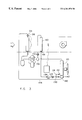
- FIG. 1 is a circuit diagram of a refrigeration circuit with a reheat coil and outdoor condenser coil in parallel circuiting arrangement in accordance with the present invention.
- FIG. 2 is a alternative embodiment of the present invention in accordance with FIG. 1 with the addition of a subcooler proximal the reheat condenser in the supply air stream.
- FIG. 3 is a further alternative embodiment of the present invention in accordance with FIG. 1 using the existing subcooler in an outdoor condenser coil.
- the present invention is directed to a 100% fresh air conditioning system which provides better indoor air quality than systems using a large percentage of recirculated air.
- FIG. 1 shows an air conditioning system 10 in accordance with the present invention.
- air conditioning system and refrigeration system shall be used interchangeably unless otherwise noted.
- the system 10 includes one or more compressors 12 each having a discharge 14 linked by refrigerant tubing 16 to an input 18 of an outdoor heat exchange coil 20 .
- the outdoor heat exchange coil 20 has an output 22 linked by refrigerant tubing 24 to an input 26 of a receiver 28 .
- the receiver 28 has an output 30 linked by refrigeration tubing 32 to an input 34 of an expansion device 36 such as a thermal expansion valve or an electronic expansion valve.
- the expansion device 36 has an output 38 linked by refrigeration tubing 40 to an input 42 of an indoor heat exchange coil 44 .
- the indoor heat exchange coil 44 has an output 46 linked by refrigeration tubing 48 to an input 50 of the one or more compressors 12 .
- the refrigerant tubing 16 , 24 , 32 , 42 and 48 collectively links the compressor 12 , the outdoor heat exchange coil 20 , the expansion device 36 and the indoor heat exchange coil 44 into a refrigeration system 52 .
- the system 10 also includes a reheat coil 60 having an input 64 connected to the compressor discharge 14 by refrigeration tubing 62 .
- the reheat coil 60 has an output 66 connected by refrigeration tubing 68 to an input 69 of a liquid control valve 70 .
- the liquid control valve 70 has an output 72 connected by refrigeration tubing 74 to the refrigeration tubing 24 .
- the liquid control valve 70 may alternatively be replaced by an on/off solenoid valve which is controlled using stepwise modulation to achieve the same effect.
- the term control valve is intended to encompass the liquid control valve 70 , the stepwise modulation of solenoid valves and other equivalents.
- the reheat coil 60 and the outdoor heat exchange coil 20 are in a parallel circuiting arrangement in the system 10 .
- Each of the reheat coil 60 and the outdoor heat exchange coil 20 are in a series circuiting arrangement with the compressor 12 , the expansion device 36 , and the indoor heat exchange coil 44 .
- the indoor heat exchange coil 44 is operably located in a supply air stream 80 bounded by supply air ducting 82 .
- a supply air fan 84 preferably is provided within the supply air ducting 82 to motivate and control the supply air flow 80 .
- the reheat coil 60 is located in the supply air flow 80 and within the supply air duct work 82 downstream of the indoor heat exchange coil 44 . Effectively, the indoor heat exchange coil 44 functions to reduce the temperature and humidity of the supply airstream 80 .
- the reheat coil 60 functions to return the supply air temperature to a desired temperature level as measured by a sensor 90 in the supply air flow 80 downstream of the reheat coil 60 .
- the system 10 shown in FIG. 1 provides and modulates reheat using free energy from the condensed refrigerant gas in the reheat coil 60 .
- the amount of refrigerant flow through the reheat coil 60 relative to the flow through the outdoor heat exchange coil 20 is determined by the liquid valve 70 placed at the exit 66 of the reheat coil 60 . Since the reheat coil 60 operates in the dehumidified supply airstream 80 downstream of the indoor heat exchange coil 44 , the tendency will be for refrigerant to condense in the reheat coil 60 rather than in the outdoor heat exchange coil 20 . This is because the dehumidified supply air downstream of the indoor heat exchange coil 44 is at the coldest point in the system 10 and is colder than the air flowing through the outdoor heat exchange coil 20 . This tendency is exploited to control the amount of reheat accomplished in the reheat coil 60 .
- liquid refrigerant is allowed to flow out of the reheat coil 60 and condensation will begin to occur within the reheat coil 60 .
- refrigerant flow to the outdoor heat exchange coil 20 will be reduced correspondingly.
- the amount of reheat can be increased by opening the liquid valve 70 further, allowing more of the liquid refrigerant to leave the reheat coil 60 and allowing more of the coil surface of the reheat coil 60 to become active in the condensation process.
- the reheat coil 60 must be properly sized to deliver the maximum required temperature rise to the supply airstream 80 when the reheat coil 60 is on the verge of becoming completely drained of liquid refrigerant.
- the amount of reheat can be controlled between the desired minimum and maximum by varying the opening of the liquid valve 70 in response to a proportional control signal generated by a controller 92 and supplied to the valve 70 by an electrical connection line 94 .
- the proportional control signal generated by the controller 92 is modulated based on a comparison of the supply air drybulb temperature measured by the sensor 90 with a setpoint conventional established within the controller 92 .
- Alternative measurements including humidity and wet bulb temperature are contemplated.
- the receiver 28 Since the volume of liquid contained by the reheat coil 60 varies considerably between the minimum and maximum reheat conditions, the receiver 28 is placed in the refrigerant tubing downstream of both the reheat coil 60 and the outdoor heat exchange coil 20 .
- the receiver 28 is sized large enough to contain all of the volume of refrigerant which can be held within the reheat coil 60 to ensure that all operational modes of the system 10 have sufficient charge.
- FIG. 2 shows an alternative embodiment of the present invention where like reference numerals are used for like elements.
- the receiver 28 is located in the supply airstream 80 in a location 100 which is downstream of the reheat coil 60 .
- a subcooler 102 is provided in the supply airstream 80 in a location proximal the reheat coil 60 .
- the subcooler 102 is serially arranged in the refrigeration circuit 52 such that an input 104 of the subcooler 102 is connected by refrigerant tubing 106 to the output 30 of the receiver 28 .
- the subcooler 102 has an output 108 connected by refrigerant tubing 110 to the input 34 of the expansion device 36 .
- FIG. 2 allows subcooling at the expansion device 36 to be reliably maintained over a wide variety of operating conditions. This is accomplished by eliminating separate subcooling sections in the outdoor heat exchange 20 and replacing those separate subcooling sections with the subcooler 102 . Additionally, the location of the receiver 28 is now upstream in the refrigeration circuit 52 of the subcooler 102 .
- the refrigerant from both the reheat coil 60 and the outdoor heat exchange coil 20 is routed first to the receiver 28 and then to the subcooler 102 .
- the subcooler 102 is located to be always operating at the lowest temperature air in the system, that air being at a location 114 immediately downstream of the discharge air from the indoor heat exchange coil 44 .
- the subcooler 102 is preferably implemented as an integral section of the reheat coil 60 with separate circuiting but may also be implemented as a separate coil.
- the receiver 28 is upstream of the subcooler 102 in the refrigeration circuit 52 to maintain a liquid seal if the temperatures and conditions are such that refrigerant flowing through the outdoor heat exchange coil 20 does not fully condense.
- the receiver 28 also acts to provide a reservoir of refrigerant charge to supply the system 10 as the reheat coil 60 fills and/or empties with liquid refrigerant during the modulation of the reheat coil by the liquid valve 70 .
- FIG. 2 also shows a suction accumulator 120 just upstream in the refrigeration circuit 52 of the compressor 12 .
- the suction accumulator 120 may be required if the total amount of system refrigerant charge is greater than specified as acceptable by the compressor manufacturer.
- the suction accumulator 120 acts to capture excess liquid refrigerant present in the refrigeration tubing under dynamic conditions such as system start-up.
- the reheat coil 60 can be flooded with liquid refrigerant by closing the liquid valve 70 to thereby modulate the heat transfer of the reheat coil 60 to near zero, the subcooler 102 will always be functioning. This means that the reheat operation cannot be completely turned off. However, since it is not desirable to have wet, nearly saturated air flowing through the duct work 82 , some minimum amount of reheat can be tolerated and is actually beneficial from an indoor air quality standpoint.
- FIG. 3 is a further alternative embodiment of the present invention where like reference numerals are used for like elements.
- a three-way valve 130 controls the flow of refrigerant to either the reheat coil 60 or the outdoor heat exchange coil 20 .
- a first check valve 132 is provided upstream of the reheat coil 60 and a second check valve 134 is provided downstream of the reheat coil 60 so as to ensure that refrigerant flow through the reheat coil can only occur in the direction indicated by arrow 136 .
- the discharge 22 from the outdoor heat exchange coil 20 is joined by the discharge 66 of the reheat coil 60 at a point 138 and the combined discharge is directed to a subcooler 140 forming an integral part of the outdoor heat exchange coil 20 .
- the subcooler 140 has a discharge 142 connected by tubing 144 to the input 34 of the expansion device 36 .
- the alternative embodiment of FIG. 3 subcools the partially condensed hot gas leaving the reheat coil 60 and equalizes the refrigerant charge required in both cooling and dehumidification operating modes. This is accomplished by using the subcooling circuit 140 typically provided in an outdoor heat exchange coil 20 and by sizing the returned piping 74 from the reheat coil 60 in order to match the required charge in the dehumidification mode to the standard factory provided refrigerant charge used in the conventional cooling mode.
Landscapes
- Engineering & Computer Science (AREA)
- Mechanical Engineering (AREA)
- General Engineering & Computer Science (AREA)
- Physics & Mathematics (AREA)
- Thermal Sciences (AREA)
- Chemical & Material Sciences (AREA)
- Combustion & Propulsion (AREA)
- Air Conditioning Control Device (AREA)
Abstract
Description
Claims (17)
Priority Applications (2)
| Application Number | Priority Date | Filing Date | Title |
|---|---|---|---|
| US09/263,391 US6381970B1 (en) | 1999-03-05 | 1999-03-05 | Refrigeration circuit with reheat coil |
| US09/982,665 US6612119B2 (en) | 1999-03-05 | 2001-10-18 | Refrigeration circuit with reheat coil |
Applications Claiming Priority (1)
| Application Number | Priority Date | Filing Date | Title |
|---|---|---|---|
| US09/263,391 US6381970B1 (en) | 1999-03-05 | 1999-03-05 | Refrigeration circuit with reheat coil |
Related Child Applications (1)
| Application Number | Title | Priority Date | Filing Date |
|---|---|---|---|
| US09/982,665 Division US6612119B2 (en) | 1999-03-05 | 2001-10-18 | Refrigeration circuit with reheat coil |
Publications (1)
| Publication Number | Publication Date |
|---|---|
| US6381970B1 true US6381970B1 (en) | 2002-05-07 |
Family
ID=23001598
Family Applications (2)
| Application Number | Title | Priority Date | Filing Date |
|---|---|---|---|
| US09/263,391 Expired - Fee Related US6381970B1 (en) | 1999-03-05 | 1999-03-05 | Refrigeration circuit with reheat coil |
| US09/982,665 Expired - Lifetime US6612119B2 (en) | 1999-03-05 | 2001-10-18 | Refrigeration circuit with reheat coil |
Family Applications After (1)
| Application Number | Title | Priority Date | Filing Date |
|---|---|---|---|
| US09/982,665 Expired - Lifetime US6612119B2 (en) | 1999-03-05 | 2001-10-18 | Refrigeration circuit with reheat coil |
Country Status (1)
| Country | Link |
|---|---|
| US (2) | US6381970B1 (en) |
Cited By (33)
| Publication number | Priority date | Publication date | Assignee | Title |
|---|---|---|---|---|
| US6666040B1 (en) | 2002-07-02 | 2003-12-23 | Desert Aire Corp. | Efficient water source heat pump with hot gas reheat |
| US6701723B1 (en) * | 2002-09-26 | 2004-03-09 | Carrier Corporation | Humidity control and efficiency enhancement in vapor compression system |
| US20040089002A1 (en) * | 2002-11-08 | 2004-05-13 | York International Corporation | System and method for using hot gas re-heat for humidity control |
| US20050022541A1 (en) * | 2002-11-08 | 2005-02-03 | York International Corporation | System and method for using hot gas re-heat for humidity control |
| US20050085178A1 (en) * | 2003-08-26 | 2005-04-21 | Bruce Hall | System and method for preventing growth of mold or mildew in a building |
| US20050115254A1 (en) * | 2002-11-08 | 2005-06-02 | York International Corporation | System and method for using hot gas reheat for humidity control |
| US20060005571A1 (en) * | 2004-07-07 | 2006-01-12 | Alexander Lifson | Refrigerant system with reheat function provided by auxiliary heat exchanger |
| US20060010908A1 (en) * | 2004-07-15 | 2006-01-19 | Taras Michael F | Refrigerant systems with reheat and economizer |
| US20060053820A1 (en) * | 2004-09-16 | 2006-03-16 | Taras Michael F | Heat pump with reheat circuit |
| US20060053823A1 (en) * | 2004-09-16 | 2006-03-16 | Taras Michael F | Heat pump with reheat and economizer functions |
| US20060053821A1 (en) * | 2004-09-16 | 2006-03-16 | Taras Michael F | Refrigerant heat pump with reheat circuit |
| US20060053822A1 (en) * | 2004-09-16 | 2006-03-16 | Taras Michael F | Multi-circuit dehumidification heat pump system |
| US20060086115A1 (en) * | 2004-10-22 | 2006-04-27 | York International Corporation | Control stability system for moist air dehumidification units and method of operation |
| US20060090507A1 (en) * | 2004-11-01 | 2006-05-04 | Carrier Corporation | Multiple condenser reheat system with tandem compressors |
| US20060090502A1 (en) * | 2004-10-28 | 2006-05-04 | Carrier Corporation | Hybrid tandem compressor system with economizer circuit and reheat function for multi-level cooling |
| US20060225444A1 (en) * | 2005-04-08 | 2006-10-12 | Carrier Corporation | Refrigerant system with variable speed compressor and reheat function |
| US20070056948A1 (en) * | 2003-08-26 | 2007-03-15 | Bruce Hall | System and Method for Preventing Growth of Mold or Mildew in a Building |
| US20090044557A1 (en) * | 2007-08-15 | 2009-02-19 | Johnson Controls Technology Company | Vapor compression system |
| US7980087B2 (en) | 2007-06-08 | 2011-07-19 | Trane International Inc. | Refrigerant reheat circuit and charge control with target subcooling |
| US20130167564A1 (en) * | 2011-12-28 | 2013-07-04 | Desert Aire Corp. | Air conditioning apparatus for efficient supply air temperature control |
| US20140260380A1 (en) * | 2013-03-15 | 2014-09-18 | Energy Recovery Systems Inc. | Compressor control for heat transfer system |
| US9016074B2 (en) | 2013-03-15 | 2015-04-28 | Energy Recovery Systems Inc. | Energy exchange system and method |
| US9234686B2 (en) | 2013-03-15 | 2016-01-12 | Energy Recovery Systems Inc. | User control interface for heat transfer system |
| CN105466091A (en) * | 2015-12-12 | 2016-04-06 | 西安交通大学 | Heat pump type air conditioner refrigerating circulating system with subcooler |
| US9322581B2 (en) | 2011-02-11 | 2016-04-26 | Johnson Controls Technology Company | HVAC unit with hot gas reheat |
| US20160169549A1 (en) * | 2013-07-01 | 2016-06-16 | Trane International Inc. | Method of controlling a fluid circulation system |
| US10260775B2 (en) | 2013-03-15 | 2019-04-16 | Green Matters Technologies Inc. | Retrofit hot water system and method |
| WO2020164213A1 (en) * | 2019-02-12 | 2020-08-20 | 珠海格力电器股份有限公司 | Air conditioning system |
| US10907845B2 (en) | 2016-04-13 | 2021-02-02 | Trane International Inc. | Multi-functional heat pump apparatus |
| CN113795126A (en) * | 2021-09-27 | 2021-12-14 | 苏州浪潮智能科技有限公司 | A server and gas-liquid coordinated cooling system |
| US11629866B2 (en) | 2019-01-02 | 2023-04-18 | Johnson Controls Tyco IP Holdings LLP | Systems and methods for delayed fluid recovery |
| US11859880B2 (en) | 2021-06-10 | 2024-01-02 | Johnson Controls Technology Company | Reheat operation for heat pump system |
| US12339024B2 (en) | 2019-09-05 | 2025-06-24 | Trane International Inc. | Efficiently routing excess air flow |
Families Citing this family (14)
| Publication number | Priority date | Publication date | Assignee | Title |
|---|---|---|---|---|
| US6792767B1 (en) | 2002-10-21 | 2004-09-21 | Aaon Inc. | Controls for air conditioner |
| US8397522B2 (en) * | 2004-04-27 | 2013-03-19 | Davis Energy Group, Inc. | Integrated dehumidification system |
| US20060218949A1 (en) * | 2004-08-18 | 2006-10-05 | Ellis Daniel L | Water-cooled air conditioning system using condenser water regeneration for precise air reheat in dehumidifying mode |
| US8220277B2 (en) * | 2006-11-07 | 2012-07-17 | Tiax Llc | Dehumidification method having multiple different refrigeration paths between the reheat and cooling coils |
| US7823404B2 (en) * | 2006-12-15 | 2010-11-02 | Lennox Industries Inc. | Air conditioning system with variable condenser reheat and refrigerant flow sequencer |
| WO2009041976A1 (en) * | 2007-09-28 | 2009-04-02 | Carrier Commercial Refrigeration, Inc. | Display case including heat exchanger for reducing relative humidity |
| US8925336B2 (en) * | 2008-04-19 | 2015-01-06 | Carrier Corporation | Refrigerant system performance enhancement by subcooling at intermediate temperatures |
| WO2010005918A2 (en) * | 2008-07-09 | 2010-01-14 | Carrier Corporation | Heat pump with microchannel heat exchangers as both outdoor and reheat heat exchangers |
| CN102620406A (en) * | 2011-01-30 | 2012-08-01 | 蓝斯(广州)能源科技有限公司 | Air cooling split air conditioner system for controlling relative humidity of indoor air |
| US9631834B2 (en) | 2011-11-21 | 2017-04-25 | Lennox Industries Inc. | Dehumidifier having split condenser configuration |
| US9328934B2 (en) * | 2013-08-05 | 2016-05-03 | Trane International Inc. | HVAC system subcooler |
| US11221151B2 (en) * | 2019-01-15 | 2022-01-11 | Johnson Controls Technology Company | Hot gas reheat systems and methods |
| CN112555997B (en) * | 2020-12-25 | 2021-12-28 | 珠海格力电器股份有限公司 | Fresh air handling unit and air outlet temperature and humidity control method thereof |
| CN116147091A (en) * | 2023-03-15 | 2023-05-23 | 上海埃昂空调制冷设备有限公司 | A plant direct expansion air conditioning unit with condensation reheating and dehumidification |
Citations (24)
| Publication number | Priority date | Publication date | Assignee | Title |
|---|---|---|---|---|
| US1837798A (en) | 1928-09-19 | 1931-12-22 | York Ice Machinery Corp | Apparatus for conditioning air |
| US1986863A (en) | 1932-11-30 | 1935-01-08 | Westinghouse Electric & Mfg Co | Cooling and dehumidifying system |
| US2107243A (en) | 1935-08-15 | 1938-02-01 | Norman H Gay | Air conditioning apparatus |
| US2154136A (en) | 1936-03-31 | 1939-04-11 | Carrier Corp | Fluid circulation system |
| US2172877A (en) | 1937-02-25 | 1939-09-12 | Carrier Corp | Air conditioning system |
| US2515842A (en) | 1947-07-16 | 1950-07-18 | Carrier Corp | System for providing reheat in bus air conditioning |
| US2657543A (en) | 1948-10-08 | 1953-11-03 | George B Scarlett | Method and apparatus for maintaining temperature and humidity constant |
| US2961844A (en) | 1957-05-02 | 1960-11-29 | Carrier Corp | Air conditioning system with reheating means |
| US3105366A (en) | 1962-05-16 | 1963-10-01 | Gen Electric | Air conditioning apparatus having reheat means |
| US3139735A (en) | 1962-04-16 | 1964-07-07 | Kramer Trenton Co | Vapor compression air conditioning system or apparatus and method of operating the same |
| US3203196A (en) | 1963-05-10 | 1965-08-31 | Kramer Trenton Co | Air conditioning system with frost control |
| US3264840A (en) | 1965-05-03 | 1966-08-09 | Westinghouse Electric Corp | Air conditioning systems with reheat coils |
| US3316730A (en) | 1966-01-11 | 1967-05-02 | Westinghouse Electric Corp | Air conditioning system including reheat coils |
| US3520147A (en) | 1968-07-10 | 1970-07-14 | Whirlpool Co | Control circuit |
| US3631686A (en) | 1970-07-23 | 1972-01-04 | Itt | Multizone air-conditioning system with reheat |
| US4270362A (en) | 1977-04-29 | 1981-06-02 | Liebert Corporation | Control system for an air conditioning system having supplementary, ambient derived cooling |
| US4271678A (en) | 1977-03-21 | 1981-06-09 | Liebert Corporation | Liquid refrigeration system for an enclosure temperature controlled outdoor cooling or pre-conditioning |
| US4483156A (en) | 1984-04-27 | 1984-11-20 | The Trane Company | Bi-directional variable subcooler for heat pumps |
| US4711094A (en) | 1986-11-12 | 1987-12-08 | Hussmann Corporation | Reverse cycle heat reclaim coil and subcooling method |
| US4920756A (en) * | 1989-02-15 | 1990-05-01 | Thermo King Corporation | Transport refrigeration system with dehumidifier mode |
| US5265433A (en) | 1992-07-10 | 1993-11-30 | Beckwith William R | Air conditioning waste heat/reheat method and apparatus |
| US5329782A (en) | 1991-03-08 | 1994-07-19 | Hyde Robert E | Process for dehumidifying air in an air-conditioned environment |
| US5622057A (en) | 1995-08-30 | 1997-04-22 | Carrier Corporation | High latent refrigerant control circuit for air conditioning system |
| US5651258A (en) | 1995-10-27 | 1997-07-29 | Heat Controller, Inc. | Air conditioning apparatus having subcooling and hot vapor reheat and associated methods |
-
1999
- 1999-03-05 US US09/263,391 patent/US6381970B1/en not_active Expired - Fee Related
-
2001
- 2001-10-18 US US09/982,665 patent/US6612119B2/en not_active Expired - Lifetime
Patent Citations (24)
| Publication number | Priority date | Publication date | Assignee | Title |
|---|---|---|---|---|
| US1837798A (en) | 1928-09-19 | 1931-12-22 | York Ice Machinery Corp | Apparatus for conditioning air |
| US1986863A (en) | 1932-11-30 | 1935-01-08 | Westinghouse Electric & Mfg Co | Cooling and dehumidifying system |
| US2107243A (en) | 1935-08-15 | 1938-02-01 | Norman H Gay | Air conditioning apparatus |
| US2154136A (en) | 1936-03-31 | 1939-04-11 | Carrier Corp | Fluid circulation system |
| US2172877A (en) | 1937-02-25 | 1939-09-12 | Carrier Corp | Air conditioning system |
| US2515842A (en) | 1947-07-16 | 1950-07-18 | Carrier Corp | System for providing reheat in bus air conditioning |
| US2657543A (en) | 1948-10-08 | 1953-11-03 | George B Scarlett | Method and apparatus for maintaining temperature and humidity constant |
| US2961844A (en) | 1957-05-02 | 1960-11-29 | Carrier Corp | Air conditioning system with reheating means |
| US3139735A (en) | 1962-04-16 | 1964-07-07 | Kramer Trenton Co | Vapor compression air conditioning system or apparatus and method of operating the same |
| US3105366A (en) | 1962-05-16 | 1963-10-01 | Gen Electric | Air conditioning apparatus having reheat means |
| US3203196A (en) | 1963-05-10 | 1965-08-31 | Kramer Trenton Co | Air conditioning system with frost control |
| US3264840A (en) | 1965-05-03 | 1966-08-09 | Westinghouse Electric Corp | Air conditioning systems with reheat coils |
| US3316730A (en) | 1966-01-11 | 1967-05-02 | Westinghouse Electric Corp | Air conditioning system including reheat coils |
| US3520147A (en) | 1968-07-10 | 1970-07-14 | Whirlpool Co | Control circuit |
| US3631686A (en) | 1970-07-23 | 1972-01-04 | Itt | Multizone air-conditioning system with reheat |
| US4271678A (en) | 1977-03-21 | 1981-06-09 | Liebert Corporation | Liquid refrigeration system for an enclosure temperature controlled outdoor cooling or pre-conditioning |
| US4270362A (en) | 1977-04-29 | 1981-06-02 | Liebert Corporation | Control system for an air conditioning system having supplementary, ambient derived cooling |
| US4483156A (en) | 1984-04-27 | 1984-11-20 | The Trane Company | Bi-directional variable subcooler for heat pumps |
| US4711094A (en) | 1986-11-12 | 1987-12-08 | Hussmann Corporation | Reverse cycle heat reclaim coil and subcooling method |
| US4920756A (en) * | 1989-02-15 | 1990-05-01 | Thermo King Corporation | Transport refrigeration system with dehumidifier mode |
| US5329782A (en) | 1991-03-08 | 1994-07-19 | Hyde Robert E | Process for dehumidifying air in an air-conditioned environment |
| US5265433A (en) | 1992-07-10 | 1993-11-30 | Beckwith William R | Air conditioning waste heat/reheat method and apparatus |
| US5622057A (en) | 1995-08-30 | 1997-04-22 | Carrier Corporation | High latent refrigerant control circuit for air conditioning system |
| US5651258A (en) | 1995-10-27 | 1997-07-29 | Heat Controller, Inc. | Air conditioning apparatus having subcooling and hot vapor reheat and associated methods |
Cited By (62)
| Publication number | Priority date | Publication date | Assignee | Title |
|---|---|---|---|---|
| US6666040B1 (en) | 2002-07-02 | 2003-12-23 | Desert Aire Corp. | Efficient water source heat pump with hot gas reheat |
| US6701723B1 (en) * | 2002-09-26 | 2004-03-09 | Carrier Corporation | Humidity control and efficiency enhancement in vapor compression system |
| US20090064711A1 (en) * | 2002-11-08 | 2009-03-12 | York International Corporation | System and method for using hot gas reheat for humidity control |
| US20040089002A1 (en) * | 2002-11-08 | 2004-05-13 | York International Corporation | System and method for using hot gas re-heat for humidity control |
| US20050022541A1 (en) * | 2002-11-08 | 2005-02-03 | York International Corporation | System and method for using hot gas re-heat for humidity control |
| US7062930B2 (en) | 2002-11-08 | 2006-06-20 | York International Corporation | System and method for using hot gas re-heat for humidity control |
| US20050115254A1 (en) * | 2002-11-08 | 2005-06-02 | York International Corporation | System and method for using hot gas reheat for humidity control |
| US7726140B2 (en) | 2002-11-08 | 2010-06-01 | York International Corporation | System and method for using hot gas re-heat for humidity control |
| US7770411B2 (en) | 2002-11-08 | 2010-08-10 | York International Corporation | System and method for using hot gas reheat for humidity control |
| US7434415B2 (en) | 2002-11-08 | 2008-10-14 | York International Corporation | System and method for using hot gas reheat for humidity control |
| US20050085178A1 (en) * | 2003-08-26 | 2005-04-21 | Bruce Hall | System and method for preventing growth of mold or mildew in a building |
| US20070056948A1 (en) * | 2003-08-26 | 2007-03-15 | Bruce Hall | System and Method for Preventing Growth of Mold or Mildew in a Building |
| WO2006016987A3 (en) * | 2004-07-07 | 2007-12-13 | Carrier Corp | Refrigerant system with reheat function provided by auxiliary heat exchanger |
| US20060005571A1 (en) * | 2004-07-07 | 2006-01-12 | Alexander Lifson | Refrigerant system with reheat function provided by auxiliary heat exchanger |
| US20060010908A1 (en) * | 2004-07-15 | 2006-01-19 | Taras Michael F | Refrigerant systems with reheat and economizer |
| WO2006019554A3 (en) * | 2004-07-15 | 2006-05-18 | Carrier Corp | Refrigerant systems with reheat and economizer |
| US7059151B2 (en) * | 2004-07-15 | 2006-06-13 | Carrier Corporation | Refrigerant systems with reheat and economizer |
| US7272948B2 (en) | 2004-09-16 | 2007-09-25 | Carrier Corporation | Heat pump with reheat and economizer functions |
| US7290399B2 (en) | 2004-09-16 | 2007-11-06 | Carrier Corporation | Multi-circuit dehumidification heat pump system |
| US7523623B2 (en) | 2004-09-16 | 2009-04-28 | Carrier Corporation | Heat pump with reheat and economizer functions |
| US20060053820A1 (en) * | 2004-09-16 | 2006-03-16 | Taras Michael F | Heat pump with reheat circuit |
| US20060053822A1 (en) * | 2004-09-16 | 2006-03-16 | Taras Michael F | Multi-circuit dehumidification heat pump system |
| US7275384B2 (en) | 2004-09-16 | 2007-10-02 | Carrier Corporation | Heat pump with reheat circuit |
| US7287394B2 (en) | 2004-09-16 | 2007-10-30 | Carrier Corporation | Refrigerant heat pump with reheat circuit |
| US20060053823A1 (en) * | 2004-09-16 | 2006-03-16 | Taras Michael F | Heat pump with reheat and economizer functions |
| US20060053821A1 (en) * | 2004-09-16 | 2006-03-16 | Taras Michael F | Refrigerant heat pump with reheat circuit |
| US20070283712A1 (en) * | 2004-09-16 | 2007-12-13 | Taras Michael F | Heat pump with reheat and economizer functions |
| US7219505B2 (en) * | 2004-10-22 | 2007-05-22 | York International Corporation | Control stability system for moist air dehumidification units and method of operation |
| US20060086115A1 (en) * | 2004-10-22 | 2006-04-27 | York International Corporation | Control stability system for moist air dehumidification units and method of operation |
| US7325414B2 (en) * | 2004-10-28 | 2008-02-05 | Carrier Corporation | Hybrid tandem compressor system with economizer circuit and reheat function for multi-level cooling |
| US20060090502A1 (en) * | 2004-10-28 | 2006-05-04 | Carrier Corporation | Hybrid tandem compressor system with economizer circuit and reheat function for multi-level cooling |
| US7469555B2 (en) * | 2004-11-01 | 2008-12-30 | Carrier Corporation | Multiple condenser reheat system with tandem compressors |
| US20060090507A1 (en) * | 2004-11-01 | 2006-05-04 | Carrier Corporation | Multiple condenser reheat system with tandem compressors |
| US20060225444A1 (en) * | 2005-04-08 | 2006-10-12 | Carrier Corporation | Refrigerant system with variable speed compressor and reheat function |
| US8418486B2 (en) * | 2005-04-08 | 2013-04-16 | Carrier Corporation | Refrigerant system with variable speed compressor and reheat function |
| US7980087B2 (en) | 2007-06-08 | 2011-07-19 | Trane International Inc. | Refrigerant reheat circuit and charge control with target subcooling |
| US20090044557A1 (en) * | 2007-08-15 | 2009-02-19 | Johnson Controls Technology Company | Vapor compression system |
| US11867413B2 (en) | 2011-02-11 | 2024-01-09 | Johnson Controls Tyco IP Holdings LLP | HVAC unit with hot gas reheat |
| US10760798B2 (en) | 2011-02-11 | 2020-09-01 | Johnson Controls Technology Company | HVAC unit with hot gas reheat |
| US9322581B2 (en) | 2011-02-11 | 2016-04-26 | Johnson Controls Technology Company | HVAC unit with hot gas reheat |
| US10247430B2 (en) | 2011-02-11 | 2019-04-02 | Johnson Controls Technology Company | HVAC unit with hot gas reheat |
| US10072854B2 (en) | 2011-02-11 | 2018-09-11 | Johnson Controls Technology Company | HVAC unit with hot gas reheat |
| US10101041B2 (en) | 2011-02-11 | 2018-10-16 | Johnson Controls Technology Company | HVAC unit with hot gas reheat |
| US10174958B2 (en) | 2011-02-11 | 2019-01-08 | Johnson Controls Technology Company | HVAC unit with hot gas reheat |
| US10184688B2 (en) * | 2011-12-28 | 2019-01-22 | Desert Aire Corp. | Air conditioning apparatus for efficient supply air temperature control |
| US20130167564A1 (en) * | 2011-12-28 | 2013-07-04 | Desert Aire Corp. | Air conditioning apparatus for efficient supply air temperature control |
| US11255573B2 (en) | 2011-12-28 | 2022-02-22 | Desert Aire Corp. | Air conditioning apparatus for efficient supply air temperature control |
| US9016074B2 (en) | 2013-03-15 | 2015-04-28 | Energy Recovery Systems Inc. | Energy exchange system and method |
| US10260775B2 (en) | 2013-03-15 | 2019-04-16 | Green Matters Technologies Inc. | Retrofit hot water system and method |
| US20140260380A1 (en) * | 2013-03-15 | 2014-09-18 | Energy Recovery Systems Inc. | Compressor control for heat transfer system |
| US9234686B2 (en) | 2013-03-15 | 2016-01-12 | Energy Recovery Systems Inc. | User control interface for heat transfer system |
| US10684025B2 (en) * | 2013-07-01 | 2020-06-16 | Trane Air Conditioning Systems (China) Co., Ltd. | Method of controlling a fluid circulation system |
| US20160169549A1 (en) * | 2013-07-01 | 2016-06-16 | Trane International Inc. | Method of controlling a fluid circulation system |
| CN105466091A (en) * | 2015-12-12 | 2016-04-06 | 西安交通大学 | Heat pump type air conditioner refrigerating circulating system with subcooler |
| US11686487B2 (en) | 2016-04-13 | 2023-06-27 | Trane International Inc. | Multi-functional HVAC indoor unit |
| US10907845B2 (en) | 2016-04-13 | 2021-02-02 | Trane International Inc. | Multi-functional heat pump apparatus |
| US11629866B2 (en) | 2019-01-02 | 2023-04-18 | Johnson Controls Tyco IP Holdings LLP | Systems and methods for delayed fluid recovery |
| WO2020164213A1 (en) * | 2019-02-12 | 2020-08-20 | 珠海格力电器股份有限公司 | Air conditioning system |
| US12339024B2 (en) | 2019-09-05 | 2025-06-24 | Trane International Inc. | Efficiently routing excess air flow |
| US11859880B2 (en) | 2021-06-10 | 2024-01-02 | Johnson Controls Technology Company | Reheat operation for heat pump system |
| CN113795126B (en) * | 2021-09-27 | 2023-09-22 | 苏州浪潮智能科技有限公司 | A server and gas-liquid collaborative cooling system |
| CN113795126A (en) * | 2021-09-27 | 2021-12-14 | 苏州浪潮智能科技有限公司 | A server and gas-liquid coordinated cooling system |
Also Published As
| Publication number | Publication date |
|---|---|
| US6612119B2 (en) | 2003-09-02 |
| US20020023443A1 (en) | 2002-02-28 |
Similar Documents
| Publication | Publication Date | Title |
|---|---|---|
| US6381970B1 (en) | Refrigeration circuit with reheat coil | |
| US8583289B2 (en) | Climate control system for data centers | |
| CA2229355C (en) | Method for controlling refrigerant based air conditioner leaving air temperature | |
| EP4036486B1 (en) | Integrated hvac system for a building | |
| US5447037A (en) | Economizer preferred cooling control | |
| KR100876185B1 (en) | Energy-saving thermo-hygrostat, sensible heat cooling method and cooling dehumidification method | |
| US12287117B2 (en) | System and method for ventilating and dehumidifying a space | |
| US20060273183A1 (en) | Method of dehumidifying an indoor space using outdoor air | |
| KR101699531B1 (en) | Computer room air-conditioner with a split heat pipe heat exchanger and the control system | |
| US20060150667A1 (en) | Heat exchanger and air conditioner using the same | |
| KR102257544B1 (en) | Energy enhanced air-conditioning system and control method thereof | |
| JP4270555B2 (en) | Reheat dehumidification type air conditioner | |
| JP2005291553A (en) | Multi-type air conditioner | |
| JP2525338B2 (en) | Defrost mechanism of heat pump type air conditioner | |
| US20110041524A1 (en) | Refrigerant system performance enhancement by subcooling at intermediate temperatures | |
| JP2006194525A (en) | Multi-room air conditioner | |
| US20090056347A1 (en) | Air conditioning and energy recovery system and method of operation | |
| JP2911253B2 (en) | Refrigerant heating multi refrigeration cycle | |
| JPH0240463A (en) | Three-pipe type water cooling heat pump unit | |
| CN214701042U (en) | Novel new fan structure | |
| KR100424102B1 (en) | Air-conditioner have a facility for protecting over cooling | |
| JP2868926B2 (en) | Refrigerant heating multi refrigeration cycle | |
| KR100308759B1 (en) | Heating air conditioner | |
| JPH07239157A (en) | Operation controlling method for air-conditioner | |
| JP3643664B2 (en) | Air conditioner |
Legal Events
| Date | Code | Title | Description |
|---|---|---|---|
| AS | Assignment |
Owner name: AMERICAN STANDARD INC., NEW JERSEY Free format text: ASSIGNMENT OF ASSIGNORS INTEREST;ASSIGNORS:KIEL, BRIAN J.;HULST, DALE A.;REEL/FRAME:009957/0644 Effective date: 19990416 Owner name: AMERICAN STANDARD INC., NEW JERSEY Free format text: ASSIGNMENT OF ASSIGNORS INTEREST;ASSIGNOR:KLOUDA, JOHN F.;REEL/FRAME:009957/0635 Effective date: 19990506 Owner name: AMERICAN STANDARD INC., NEW JERSEY Free format text: ASSIGNMENT OF ASSIGNORS INTEREST;ASSIGNORS:EBER, DAVID H.;GLAMM, PAUL R.;JOHNSON, DWAYNE L.;AND OTHERS;REEL/FRAME:009957/0313 Effective date: 19990505 |
|
| AS | Assignment |
Owner name: AMERICAN STANDARD INTERNATIONAL INC., NEW YORK Free format text: NOTICE OF ASSIGNMENT;ASSIGNOR:AMERICAN STANDARD INC., A CORPORATION OF DELAWARE;REEL/FRAME:011474/0650 Effective date: 20010104 |
|
| FEPP | Fee payment procedure |
Free format text: PAYOR NUMBER ASSIGNED (ORIGINAL EVENT CODE: ASPN); ENTITY STATUS OF PATENT OWNER: LARGE ENTITY |
|
| FPAY | Fee payment |
Year of fee payment: 4 |
|
| AS | Assignment |
Owner name: TRANE INTERNATIONAL INC., NEW YORK Free format text: CHANGE OF NAME;ASSIGNOR:AMERICAN STANDARD INTERNATIONAL INC.;REEL/FRAME:020733/0970 Effective date: 20071128 Owner name: TRANE INTERNATIONAL INC.,NEW YORK Free format text: CHANGE OF NAME;ASSIGNOR:AMERICAN STANDARD INTERNATIONAL INC.;REEL/FRAME:020733/0970 Effective date: 20071128 |
|
| FPAY | Fee payment |
Year of fee payment: 8 |
|
| REMI | Maintenance fee reminder mailed | ||
| LAPS | Lapse for failure to pay maintenance fees | ||
| STCH | Information on status: patent discontinuation |
Free format text: PATENT EXPIRED DUE TO NONPAYMENT OF MAINTENANCE FEES UNDER 37 CFR 1.362 |
|
| FP | Lapsed due to failure to pay maintenance fee |
Effective date: 20140507 |