US6381101B1 - Non contact head load/unload apparatus and method for disc drives - Google Patents
Non contact head load/unload apparatus and method for disc drives Download PDFInfo
- Publication number
- US6381101B1 US6381101B1 US09/475,817 US47581799A US6381101B1 US 6381101 B1 US6381101 B1 US 6381101B1 US 47581799 A US47581799 A US 47581799A US 6381101 B1 US6381101 B1 US 6381101B1
- Authority
- US
- United States
- Prior art keywords
- disc
- flexure
- slider
- airfoil
- attached
- Prior art date
- Legal status (The legal status is an assumption and is not a legal conclusion. Google has not performed a legal analysis and makes no representation as to the accuracy of the status listed.)
- Expired - Lifetime
Links
Images


Classifications
-
- G—PHYSICS
- G11—INFORMATION STORAGE
- G11B—INFORMATION STORAGE BASED ON RELATIVE MOVEMENT BETWEEN RECORD CARRIER AND TRANSDUCER
- G11B5/00—Recording by magnetisation or demagnetisation of a record carrier; Reproducing by magnetic means; Record carriers therefor
- G11B5/48—Disposition or mounting of heads or head supports relative to record carriers ; arrangements of heads, e.g. for scanning the record carrier to increase the relative speed
- G11B5/58—Disposition or mounting of heads or head supports relative to record carriers ; arrangements of heads, e.g. for scanning the record carrier to increase the relative speed with provision for moving the head for the purpose of maintaining alignment of the head relative to the record carrier during transducing operation, e.g. to compensate for surface irregularities of the latter or for track following
- G11B5/60—Fluid-dynamic spacing of heads from record-carriers
-
- G—PHYSICS
- G11—INFORMATION STORAGE
- G11B—INFORMATION STORAGE BASED ON RELATIVE MOVEMENT BETWEEN RECORD CARRIER AND TRANSDUCER
- G11B21/00—Head arrangements not specific to the method of recording or reproducing
- G11B21/02—Driving or moving of heads
- G11B21/12—Raising and lowering; Back-spacing or forward-spacing along track; Returning to starting position otherwise than during transducing operation
-
- G—PHYSICS
- G11—INFORMATION STORAGE
- G11B—INFORMATION STORAGE BASED ON RELATIVE MOVEMENT BETWEEN RECORD CARRIER AND TRANSDUCER
- G11B21/00—Head arrangements not specific to the method of recording or reproducing
- G11B21/16—Supporting the heads; Supporting the sockets for plug-in heads
- G11B21/22—Supporting the heads; Supporting the sockets for plug-in heads while the head is out of operative position
-
- G—PHYSICS
- G11—INFORMATION STORAGE
- G11B—INFORMATION STORAGE BASED ON RELATIVE MOVEMENT BETWEEN RECORD CARRIER AND TRANSDUCER
- G11B5/00—Recording by magnetisation or demagnetisation of a record carrier; Reproducing by magnetic means; Record carriers therefor
- G11B5/48—Disposition or mounting of heads or head supports relative to record carriers ; arrangements of heads, e.g. for scanning the record carrier to increase the relative speed
- G11B5/54—Disposition or mounting of heads or head supports relative to record carriers ; arrangements of heads, e.g. for scanning the record carrier to increase the relative speed with provision for moving the head into or out of its operative position or across tracks
Definitions
- This application relates generally to the field of disc drive storage devices, and more particularly, to an apparatus and method for minimizing contact and friction between a disc and a head/slider assembly within a disc drive.
- Disc drives are data storage devices that store digital data in magnetic form on a rotating storage medium, such as a disc.
- Modern disc drives comprise one or more rigid discs that are coated with a magnetizable medium and mounted on the hub of a drive motor for rotation at a constant high speed.
- Information is stored on the discs in a plurality of concentric circular tracks typically by an array of transducers (“heads”) each mounted on a slider.
- heads each mounted on a slider.
- Each slider is supported on a flexure attached to an actuator arm which is part of an actuator assembly that moves the head relative to the discs.
- Each transducer e.g., a magnetoresistive read/write head, is used to transfer data between a desired track and an external environment.
- the head writes the data onto the disc track, and during a read operation, the head senses the data previously written on the disc track and transfers the information to a disc drive circuit board in the external environment.
- the slider with the head is mounted via flexures at the end of an actuator arm that projects radially outward from an actuator body In the actuator assembly.
- the actuator body pivots about a bearing assembly mounted on a base plate at a position closely adjacent to the outer extreme of the discs.
- the head(s) read data and transfer it along the actuator arm to a preamplifier which amplifies the signals coming from the heads.
- the actuator assembly includes a voice coil motor to position the heads with respect to the disc surfaces.
- the actuator voice coil motor includes a coil mounted to the actuator body opposite the actuator arm and is immersed in the magnetic field of a magnetic circuit comprising one or more permanent magnets and magnetically permeable pole pieces.
- DC direct current
- an electromagnetic field is set up which interacts with the magnetic field of the magnetic circuit to cause the coil to move in accordance with the well-known Lorentz relationship.
- the actuator body and arm pivot about the bearing assembly and the heads move across the disc surfaces.
- the slider support assembly has been loaded or biased by the flexure so that the slider applies a vertical pressure on the disc surface.
- the air pressure between the disc and slider overcomes the vertical downward pressure and causes the slider assembly to fly slightly above the disc surface at a flying height such that there is no friction between the disc surface and the slider.
- the actuator assembly is typically positioned with the sliders over a portion of the disc surface that contains no sensitive data when the disc drive is not operating, such as the inner most track or margin of the discs.
- the inner most track is often called the landing zone and typically contains no magnetic recorded information.
- loading ramp located beyond the outer diameter of the disc in a disc drive.
- the slider When the disc drive is not operating, the slider is driven out of the disc area and loaded and parked onto the ramp. In this way, the loading ramp frees up the storage space on the inner diameter of the disc.
- loading ramps can cause the problem of wear particle generation within the disc drive.
- Loading ramps also may cause the problem of scratching and nicking of the tracks near the outer diameter of the disc surface caused when the slider contacts the disc surface during the loading and unloading of the slider on the ramp.
- typically a landing zone is created on the outer diameter of the disc which can waste actually more valuable disc space than the landing zone on the inner diameter of the disc.
- Another solution is to load the actuator assembly such that the slider is biased away from the surface of the disc when the disc is at a standstill. In this way, the entire disc surface could be used to store data. However, with the slider biased away from the disc surface, there must be a force to move the slider towards the disc surface and into flying height when the disc is spinning during the operation of the disc drive.
- Another problematic way to create a force which moves the slider towards the disc during disc drive operation is to include an aerodynamic airfoil formed out of the actuator arm which exerts a negative lift force towards the disc and thereby moves the slider into flying height position.
- the size of the airfoil is limited by the diameter of the actuator arm and therefore may not provide enough force in smaller disc drives.
- the size and angle of the airfoil is limited by the distance between the slider and the disc surface, and thus, the airfoil may not be large enough to create sufficient downward force in smaller disc drives.
- a head disc assembly in a disc drive has a base plate and a top cover which encloses a drive motor, a disc supported thereon, and an actuator assembly.
- the disc spins at a given velocity during operation of the disc drive which causes air flow within the head disc assembly.
- the actuator assembly has an actuator arm which transfers data to and from the disc.
- a flexure has one end connected to the slider and an opposite end connected to the actuator arm. When the disc is stationary, the flexure and the slider are biased away from the disc.
- One or more airfoils are attached to the flexure and extend from the flexure at an angle relative to the disc so as to interact with the air flow to force the flexure and the attached slider to move toward the disc during operation of the disc drive.
- FIG. 1 is a plan view of a disc drive head disc assembly incorporating aerodynamic airfoils in accordance with one preferred embodiment of the invention with the head disc assembly cover partially broken away.
- FIG. 2 is a separate perspective view of the flexure with attached airfoils in accordance with a preferred embodiment of the invention and illustrates the positioning of two alternative embodiments with dashed lines.
- FIG. 3 shows an enlarged top view of the head support end of the flexure in FIG. 2 with airfoils attached to the head carrier in accordance with one of the alternative preferred embodiments of the present invention.
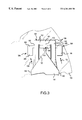
- FIG. 4 illustrates a side view of the flexure depicted in FIG. 2 showing the two alternative embodiments with dashed lines.
- FIG. 1 A disc drive 100 constructed in accordance with one preferred embodiment of the present invention is shown in FIG. 1 .
- the disc drive 100 includes a metal base plate 102 to which various components of the disc drive 100 are mounted.
- a metal top cover 104 cooperates with the base plate 102 to form an internal, sealed environment for the disc drive components in a conventional manner.
- the components include a drive motor 106 which rotates one or more discs 108 at a constant high speed in the direction of arrow 109 .
- Information is written to and read from tracks on each of the discs 108 through the use of an actuator assembly 110 , which rotates about a bearing shaft assembly 112 positioned adjacent the discs 108 .
- the actuator assembly 110 further includes an actuator body, or E-Block, having one or more actuator arms 114 , which extend towards the discs 108 , with one or more flexures 116 extending from each actuator arm 114 .
- an actuator body or E-Block
- the slider 120 enables the head 118 to fly in close proximity (or at a “flying height”) above the corresponding surface of the associated disc 108 .
- the flying height is a height at which the head can read from and write data onto a disc while not touching the disc surface.
- the radial position of the slider 120 and its head 118 is controlled through the use of a voice coil motor (VCM) 124 .
- VCM voice coil motor
- the VCM 124 typically includes a coil 126 attached to the actuator assembly 110 , as well as one or more permanent magnets 128 which establish a magnetic field in which the coil 126 is immersed.
- the controlled application of current to the coil 126 causes magnetic interaction between the permanent magnets 128 and the coil 126 so that the coil 126 moves in accordance with the well known Lorentz relationship.
- the actuator assembly 110 pivots about the bearing shaft assembly 112 and the heads 118 are caused to move across the surfaces of the discs 108 .
- a flex circuit 132 provides the requisite: electrical connection paths for the actuator assembly 110 while allowing pivotal movement of the actuator assembly 110 during operation.
- the flex circuit includes a preamplifier 130 , a flexible ribbon portion 134 , and a fixed ribbon portion 136 .
- Head wires or electrical traces (not shown) are connected from the heads 118 along the flexures 116 and routed along the actuator arm 114 to the preamplifier 130 .
- the preamplifier 130 typically includes circuitry for controlling the write currents applied to the heads 118 during a write operation and for amplifying read signals generated by the heads 118 during a read operation.
- the flexible ribbon portion 134 of the flex circuit 132 connects the preamplifier 130 to the fixed portion 136 of the flex circuit 132 .
- the fixed portion 136 of the flex circuit 132 is mounted to a flex circuit support bracket 138 which is, in turn, mounted to the base plate 102 with a flex bracket screw 142 .
- a pair of aerodynamic airfoils or wings 164 are attached to the flexure 116 at an angle with respect to the disc surface such that when the disc 108 begins to spin and generate air movement the air will flow onto upper surfaces of the airfoils 164 , as shown in FIG. 1 .
- the force of air flow against the airfoils 164 , and thus, the flexure 116 and the slider 120 forces the slider 120 towards the surface of the disc 108 .
- an opposing force arising from the air layer adjacent the surface of the spinning disc 108 will push against an air bearing surface on the slider 120 and lift the slider 120 away from the surface of the disc 108 .
- These counterbalancing forces act to position the slider 120 and the head 118 at an optimal flying height above the disc for reading data from or writing data to the disc 108 without causing the slider 120 to contact the disc 108 .
- the airfoils 164 are sufficiently rigid such that they will not deform after extended use or under air pressure during disc drive operation.
- the size, shape, and angle of the airfoils 164 are configured as a function of the velocity of the disc 108 during operation of the disc drive 100 to balance the slider 120 at flying height during disc drive operation.
- FIG. 2 illustrates a separate perspective view of the flexure 116 with attached airfoils 164 in accordance with one preferred embodiment of the invention shown in FIG. 1 .
- the flexure 116 includes a load beam 144 and a flex cable 152 .
- the load beam 144 has a distal end 146 positioned near the slider 120 and an opposite end 148 which is attached to the actuator arm 114 (not shown in FIG. 2 ).
- the flex cable 152 is attached to the load beam 144 by welding points at apertures 153 and 154 along the load beam 144 , as best seen in FIG.
- the flex cable 152 includes a carrier 156 , made of polyamide or other preferably suitable materials, electrical traces (not shown), and a gimbal insert 158 .
- the gimbal insert 158 is preferably a metallic material, for example iron-chromium (FeCr).
- the gimbal insert is U-shaped with distal end 161 and opposite sides 162 . Airfoils 164 are attached to the load beam 144 and are angled towards the disc 108 .
- FIG. 2 also shows two alternative embodiments of the present invention with dashed lines.
- a pair of airfoils 264 are attached to the load beam 144 and angle toward the disc 108 .
- airfoils 364 are attached to sides 162 of the gimbal insert 158 and are angled towards the disc 108 . Airfoils 364 may also be attached to the gimbal insert 158 and angled away from the disc similar to airfoils 164 .
- FIG. 3 shows an enlarged top view of the gimbal insert end of the flexure 116 in accordance with the second alternative preferred embodiment of the present invention just mentioned.
- a central arm 160 of the gimbal insert 158 extends away from distal end 161 of the gimbal insert 158 back toward the load beam 144 .
- the slider 120 is mounted to central arm 160 of the gimbal insert 158 such that the electrical traces are electrically coupled to the magnetic head 118 on the slider 120 .
- Airfoils 364 are each fastened to one of the sides 162 of the gimbal insert 158 and extend outward from flexure 116 .
- the airfoils 364 are connected to the sides 162 and the slider 120 is connected to central arm 160 , the air flow over the airfoils 364 will not affect the pitch and roll angle of slider 120 .
- the air flow force will act against the sides 162 of the gimbal insert 158 .
- the slider 120 is mounted or attached to central arm 160 of gimbal insert 158 such that when flex cable 152 is attached to load beam 144 via welding points 153 and 154 , a load tab or button 150 on load beam 144 applies pre-load force on flex cable 152 , and thus on slider 120 , such that the slider 120 is biased away from the disc 108 when the disc 108 is not spinning.
- the airfoils 164 each include a body 166 and base 168 .
- the base 168 is a flat piece of material positioned in the same plane as the flexure 116 and is attached to outer edges of the flexure 116 , i.e., to the outer edges 145 of the load beam 144 .
- the body 166 of the airfoil 164 is angled away from the plane of the airfoil base 168 .
- the airfoils 264 each include an airfoil body 266 and an airfoil base 268 .
- the airfoil bases 268 are attached to the outer edges 145 of the load beam 144 .
- the length of airfoils 264 are also not limited by the distance between the slider 120 and the disc 108 because the airfoils may extend away from the plane of the flexure 116 in a direction away from the disc 108 , as shown in FIG. 1 .
- the width of the airfoils 164 or 264 is not limited by the size and width of the load beam 144 since the airfoils 164 or 264 are attached to outer edges 145 of the load beam 144 .
- the airfoils 164 or 264 may be formed integrally with the outer edges 145 of the load beam 144 .
- a single airfoil 164 or 264 could be attached to the middle of the load beam 144 and extend outward from the middle of the load beam 144 .
- the airfoil 364 includes an airfoil body 366 and an airfoil base 368 .
- the airfoil bases 368 are attached to the sides 162 of the gimbal insert 158 .
- the airfoils 364 may be attached at any point along the sides 162 of the gimbal insert 158 .
- the airfoils 364 may be attached with welding points, adhesive, or any other conventional attaching means.
- the airfoils 364 may be formed integrally with gimbal insert 158 . Since the airfoils 364 are attached to the sides 162 of the gimbal insert 158 , and not the central arm 160 , the air flow over the airfoils 364 will not affect the pitch and roll angle of the slider 120 .
- the airfoil body 166 , 266 , or 366 may be of any size, shape, or angle as is necessary to create the right amount of force on the flexure 116 to balance the opposite force from the disc such that the slider 120 is positioned at flying height while the disc 108 is spinning at operating speed.
- the size, shape, and angle of the airfoil body 166 , 266 , or 366 will depend upon many factors including, but not limited to, the number of discs 108 in the disc drive 100 , the speed at which the disc 108 spins at operating speed, the size of the disc drive 100 and its components, and the material composition of the disc drive components.
- the body 166 or 366 of the airfoil 164 or 364 is generally aligned with the direction of air flow 109 creating a force sufficient to move the slider 120 towards the disc during disc drive 100 operation when the actuator arm 114 occupies any position between the inner and outer diameters of the disc 108 . Since the slider 120 only moves a matter of a few centimeters between the inner diameter and outer diameter of the disc 108 , the difference between the force caused by airflow over airfoils 164 or 364 at the inner diameter and the outer diameter of the disc 108 is negligible.
- the present invention preferably is an apparatus for minimizing contact between a slider (such as 120 ) and a disc (such as 108 ) within a head disc assembly in a disc drive (such as 100 ).
- the head disc assembly has a base plate (such as 102 ) and a top cover (such as 104 ) which encloses a drive motor (such as 106 ) and an actuator assembly (such as 110 ).
- the spinning disc (such as 108 ) causes air flow within the head disc assembly.
- the drive motor (such as 106 ) supports a disc (such as 108 ) which spins at a given velocity during disc drive operation.
- the head disc assembly also has an actuator assembly (such as 110 ) including an actuator arm (such as 114 ) for transferring data to and from the disc (such as 108 ).
- a flexure (such as 116 ) has one end (such as 117 ) connected to the slider (such as 120 ) and an opposite end connected to the actuator arm (such as 114 ) and the flexure (such as 116 ) and the slider (such as 120 ) are biased away from the disc (such as 108 ) when the disc drive is not in operation.
- One or more airfoils are attached to the flexure (such as 116 ) and extends from the flexure (such as 116 ) at an angle relative to the disc (such as 108 ) so as to interact with the air flow to force the flexure (such as 116 ) and the attached slider (such as 120 ) to move toward the disc (such as 108 ) during operation of the disc drive (such as 100 ).
- the flexure ( 116 ) has a load beam (such as 144 ) and a flex cable (such as 152 ).
- the load beam (such as 144 ) has one end (such as 148 ) connected to the actuator arm (such as 114 ).
- the flex cable (such as 152 ) is connected to an opposite end (such as 146 ) of the load beam (such as 144 ) from the actuator arm (such as 114 ) and comprises a carrier (such as 156 ) and a U-shaped gimbal insert (such as 158 ) having a distal end (such as 161 ), two opposite side portions (such as 162 ) extending toward the actuator arm (such as 114 ) and fastened to the load beam (such as 144 ), and a central arm (such as 160 ) extending from the distal end (such as 161 ) of the gimbal insert (such as 158 ) toward the actuator arm (such as 114 ), wherein the slider (such as 120 ) is connected to the central arm (such as 160 ) on the gimbal insert (such as 158 ).
- the airfoils may be attached to side portions (such as 162 ) of the gimbal insert (such as 158 ) or may be formed integrally with the side portions (such as 162 ) of the gimbal insert (such as 158 ).
- the airfoils such as ( 164 or 264 ) may be attached to the load beam (such as 144 ) or may be formed integrally with the load beam (such as 144 ).
- the airfoils (such as 164 ) may have at least a portion (such as 166 ) which extends above the flexure (such as 116 ) and away from the disc (such as 108 ).
- a portion (such as 266 or 366 ) of the airfoils may extend towards the disc (such as 108 ).
- the airfoils (such as 164 , 264 , or 364 ) are substantially rigid.
- a method for minimizing damage to a disc within a head disc assembly in a disc drive is as follows.
- the flexure (such as 116 ) is loaded onto the actuator arm (such as 114 ) such that the slider (such as 120 ) is biased away from the disc (such as 108 ) when the disc is stationary.
- At least one airfoil (such as 164 , 264 , and 364 ) is affixed on the flexure (such as 116 ) to react with the air flow and force the flexure (such as 116 ) and the slider (such as 120 ) toward the disc (such as 108 ) during operation of the disc drive (such as 100 ).
- the slider (such as 120 ) floats on a layer of air such that the slider (such as 120 ) maintains a desired flying height above the disc (such as 108 ) during operation of the disc drive (such as 100 ).
- the airfoil (such as 164 , 264 , or 364 ) may be affixed by forming the airfoil (such as 164 , 264 , or 364 ) integrally with the flexure (such as 116 ) or by attaching a separate airfoil (such as 164 , 264 , or 364 ) to the flexure (such as 116 ) with welding points.
- the present invention is well adapted to attain the ends and advantages mentioned as well as those inherent therein. While presently preferred embodiments have been described for purposes of this disclosure, numerous changes may be made which will readily suggest themselves to those skilled in the art.
- the present invention may contain a single airfoil or any number of airfoils. A pair of airfoils could be attached to the gimbal insert and a pair of airfoils could be attached to the load beam. A portion of the airfoil could extend toward the disc and a portion could extend away from the disc. Accordingly, all such modifications, changes and alternatives are encompassed in the spirit of the invention disclosed and as defined in the appended claims.
Abstract
Description
Claims (20)
Priority Applications (1)
| Application Number | Priority Date | Filing Date | Title |
|---|---|---|---|
| US09/475,817 US6381101B1 (en) | 1999-04-21 | 1999-12-30 | Non contact head load/unload apparatus and method for disc drives |
Applications Claiming Priority (2)
| Application Number | Priority Date | Filing Date | Title |
|---|---|---|---|
| US13029399P | 1999-04-21 | 1999-04-21 | |
| US09/475,817 US6381101B1 (en) | 1999-04-21 | 1999-12-30 | Non contact head load/unload apparatus and method for disc drives |
Publications (1)
| Publication Number | Publication Date |
|---|---|
| US6381101B1 true US6381101B1 (en) | 2002-04-30 |
Family
ID=26828337
Family Applications (1)
| Application Number | Title | Priority Date | Filing Date |
|---|---|---|---|
| US09/475,817 Expired - Lifetime US6381101B1 (en) | 1999-04-21 | 1999-12-30 | Non contact head load/unload apparatus and method for disc drives |
Country Status (1)
| Country | Link |
|---|---|
| US (1) | US6381101B1 (en) |
Cited By (7)
| Publication number | Priority date | Publication date | Assignee | Title |
|---|---|---|---|---|
| US20020110026A1 (en) * | 2000-09-12 | 2002-08-15 | Menachem Rafaelof | Head suspension assembly with fins |
| US6545842B2 (en) * | 2001-01-19 | 2003-04-08 | Seagate Technology Llc | Disc drive actuator assembly drag reduction features |
| US6587311B1 (en) * | 1999-12-13 | 2003-07-01 | Fujitsu Limited | Magnetic storage device having a head suspension |
| US6735036B1 (en) * | 2000-01-13 | 2004-05-11 | Seagate Technology Llc | Control of data sensor fly height |
| US20040252402A1 (en) * | 2003-05-28 | 2004-12-16 | Matsushita Electric Industrial Co., Ltd. | Magnetic head lifting and lowering device |
| US20050041331A1 (en) * | 2003-08-21 | 2005-02-24 | Seagate Technology Llc | Disc stabilization system |
| US20050157430A1 (en) * | 2004-01-15 | 2005-07-21 | Seagate Technology Llc | Endcap for reducing airflow excitation of head gimbal assembly |
Citations (4)
| Publication number | Priority date | Publication date | Assignee | Title |
|---|---|---|---|---|
| JPS5580857A (en) * | 1978-12-15 | 1980-06-18 | Fujitsu Ltd | Magnetic disk memory device |
| JPH03212870A (en) * | 1990-01-17 | 1991-09-18 | Fujitsu Ltd | Magnetic head |
| JPH09204748A (en) * | 1996-01-29 | 1997-08-05 | Nec Ibaraki Ltd | Magnetic head supporting body |
| US6002552A (en) * | 1997-06-12 | 1999-12-14 | Read-Rite Corporation | Adaptive loading/unloading suspension |
-
1999
- 1999-12-30 US US09/475,817 patent/US6381101B1/en not_active Expired - Lifetime
Patent Citations (4)
| Publication number | Priority date | Publication date | Assignee | Title |
|---|---|---|---|---|
| JPS5580857A (en) * | 1978-12-15 | 1980-06-18 | Fujitsu Ltd | Magnetic disk memory device |
| JPH03212870A (en) * | 1990-01-17 | 1991-09-18 | Fujitsu Ltd | Magnetic head |
| JPH09204748A (en) * | 1996-01-29 | 1997-08-05 | Nec Ibaraki Ltd | Magnetic head supporting body |
| US6002552A (en) * | 1997-06-12 | 1999-12-14 | Read-Rite Corporation | Adaptive loading/unloading suspension |
Cited By (9)
| Publication number | Priority date | Publication date | Assignee | Title |
|---|---|---|---|---|
| US6587311B1 (en) * | 1999-12-13 | 2003-07-01 | Fujitsu Limited | Magnetic storage device having a head suspension |
| US6735036B1 (en) * | 2000-01-13 | 2004-05-11 | Seagate Technology Llc | Control of data sensor fly height |
| US20020110026A1 (en) * | 2000-09-12 | 2002-08-15 | Menachem Rafaelof | Head suspension assembly with fins |
| US6545842B2 (en) * | 2001-01-19 | 2003-04-08 | Seagate Technology Llc | Disc drive actuator assembly drag reduction features |
| US20040252402A1 (en) * | 2003-05-28 | 2004-12-16 | Matsushita Electric Industrial Co., Ltd. | Magnetic head lifting and lowering device |
| US20050041331A1 (en) * | 2003-08-21 | 2005-02-24 | Seagate Technology Llc | Disc stabilization system |
| US6961209B2 (en) * | 2003-08-21 | 2005-11-01 | Seagate Technology Llc | Disc stabilization system |
| US20050157430A1 (en) * | 2004-01-15 | 2005-07-21 | Seagate Technology Llc | Endcap for reducing airflow excitation of head gimbal assembly |
| US8416535B2 (en) * | 2004-01-15 | 2013-04-09 | Seagate Technology Llc | Endcap for reducing airflow excitation of head gimbal assembly |
Similar Documents
| Publication | Publication Date | Title |
|---|---|---|
| US6965501B1 (en) | Integrated lead suspension for high density drive | |
| US6151197A (en) | Water slide suspension assembly having a stiffened vertically offset lift tab | |
| US6480361B1 (en) | Movable load ramps and crash stop for a disc drive | |
| US6473270B1 (en) | Actuator shock snubber | |
| US6545842B2 (en) | Disc drive actuator assembly drag reduction features | |
| US6157520A (en) | Disc drive head suspension with gimbal contact feature for ramp load/unload | |
| US7130157B2 (en) | Head suspension having a displacement limiter | |
| US6483670B1 (en) | Head assembly having an apertured reinforcing plate cooperatively attached to a load beam to prevent excessive movement of components of the head assembly | |
| US20020075602A1 (en) | Head gimbal assembly flexure arm displacement limiter | |
| JP2007095240A (en) | Data storage device | |
| US6611402B1 (en) | Pitch-adjustable head suspension with end lift tab for dynamic load/unload | |
| US7733610B2 (en) | Load/unload ramp for an actuator assembly in a data storage device | |
| US6914752B2 (en) | Magnetic recording disk drive with continuous contact air-bearing slider | |
| US6747849B1 (en) | High performance suspension with reduced flow-induced vibration | |
| US6381101B1 (en) | Non contact head load/unload apparatus and method for disc drives | |
| US6181519B1 (en) | Tri-pad air bearing head slider having leading edge and trailing edge of air bearing side pads tapered to minimize takeoff and landing velocity and time | |
| US20020048123A1 (en) | Head actuator with head support excitation shield | |
| KR100434748B1 (en) | Ramp load assembly for a disc drive | |
| US7830639B2 (en) | Data storage device and disk drive | |
| EP0986049A1 (en) | Head assembly and disk drive | |
| US7262939B2 (en) | System, method, and apparatus for attaching top pole piece of a voice coil motor to a hard disk drive enclosure | |
| US7352532B2 (en) | Method and apparatus for utilizing a small pad to increase a head to a disk interface reliability for a load/unload drive | |
| US6680823B2 (en) | Moveable outer stop | |
| US6831814B2 (en) | Flexure design providing improved lift-off in a disk drive | |
| JP2006004513A (en) | Disk device and arm coil support assembly |
Legal Events
| Date | Code | Title | Description |
|---|---|---|---|
| AS | Assignment |
Owner name: SEAGATE TECHNOLOGY, INC., CALIFORNIA Free format text: ASSIGNMENT OF ASSIGNORS INTEREST;ASSIGNORS:MOHAJERANI, KHOSROW;DAGUE, WALLIS ALLEN;REEL/FRAME:010701/0655 Effective date: 20000404 |
|
| STCF | Information on status: patent grant |
Free format text: PATENTED CASE |
|
| AS | Assignment |
Owner name: JPMORGAN CHASE BANK, AS COLLATERAL AGENT, NEW YORK Free format text: SECURITY AGREEMENT;ASSIGNOR:SEAGATE TECHNOLOGY LLC;REEL/FRAME:013177/0001 Effective date: 20020513 Owner name: JPMORGAN CHASE BANK, AS COLLATERAL AGENT,NEW YORK Free format text: SECURITY AGREEMENT;ASSIGNOR:SEAGATE TECHNOLOGY LLC;REEL/FRAME:013177/0001 Effective date: 20020513 |
|
| AS | Assignment |
Owner name: JPMORGAN CHASE BANK, AS COLLATERAL AGENT, NEW YORK Free format text: SECURITY INTEREST;ASSIGNOR:SEAGATE TECHNOLOGY LLC;REEL/FRAME:013516/0015 Effective date: 20020513 |
|
| FEPP | Fee payment procedure |
Free format text: PAYOR NUMBER ASSIGNED (ORIGINAL EVENT CODE: ASPN); ENTITY STATUS OF PATENT OWNER: LARGE ENTITY |
|
| FPAY | Fee payment |
Year of fee payment: 4 |
|
| AS | Assignment |
Owner name: SEAGATE TECHNOLOGY LLC, CALIFORNIA Free format text: RELEASE OF SECURITY INTERESTS IN PATENT RIGHTS;ASSIGNOR:JPMORGAN CHASE BANK, N.A. (FORMERLY KNOWN AS THE CHASE MANHATTAN BANK AND JPMORGAN CHASE BANK), AS ADMINISTRATIVE AGENT;REEL/FRAME:016958/0294 Effective date: 20051130 |
|
| AS | Assignment |
Owner name: JPMORGAN CHASE BANK, N.A., AS ADMINISTRATIVE AGENT Free format text: SECURITY AGREEMENT;ASSIGNORS:MAXTOR CORPORATION;SEAGATE TECHNOLOGY LLC;SEAGATE TECHNOLOGY INTERNATIONAL;REEL/FRAME:022757/0017 Effective date: 20090507 Owner name: WELLS FARGO BANK, NATIONAL ASSOCIATION, AS COLLATE Free format text: SECURITY AGREEMENT;ASSIGNORS:MAXTOR CORPORATION;SEAGATE TECHNOLOGY LLC;SEAGATE TECHNOLOGY INTERNATIONAL;REEL/FRAME:022757/0017 Effective date: 20090507 |
|
| FPAY | Fee payment |
Year of fee payment: 8 |
|
| AS | Assignment |
Owner name: MAXTOR CORPORATION, CALIFORNIA Free format text: RELEASE;ASSIGNOR:JPMORGAN CHASE BANK, N.A., AS ADMINISTRATIVE AGENT;REEL/FRAME:025662/0001 Effective date: 20110114 Owner name: SEAGATE TECHNOLOGY LLC, CALIFORNIA Free format text: RELEASE;ASSIGNOR:JPMORGAN CHASE BANK, N.A., AS ADMINISTRATIVE AGENT;REEL/FRAME:025662/0001 Effective date: 20110114 Owner name: SEAGATE TECHNOLOGY HDD HOLDINGS, CALIFORNIA Free format text: RELEASE;ASSIGNOR:JPMORGAN CHASE BANK, N.A., AS ADMINISTRATIVE AGENT;REEL/FRAME:025662/0001 Effective date: 20110114 Owner name: SEAGATE TECHNOLOGY INTERNATIONAL, CALIFORNIA Free format text: RELEASE;ASSIGNOR:JPMORGAN CHASE BANK, N.A., AS ADMINISTRATIVE AGENT;REEL/FRAME:025662/0001 Effective date: 20110114 |
|
| AS | Assignment |
Owner name: THE BANK OF NOVA SCOTIA, AS ADMINISTRATIVE AGENT, Free format text: SECURITY AGREEMENT;ASSIGNOR:SEAGATE TECHNOLOGY LLC;REEL/FRAME:026010/0350 Effective date: 20110118 |
|
| AS | Assignment |
Owner name: SEAGATE TECHNOLOGY US HOLDINGS, INC., CALIFORNIA Free format text: TERMINATION AND RELEASE OF SECURITY INTEREST IN PATENT RIGHTS;ASSIGNOR:WELLS FARGO BANK, NATIONAL ASSOCIATION, AS COLLATERAL AGENT AND SECOND PRIORITY REPRESENTATIVE;REEL/FRAME:030833/0001 Effective date: 20130312 Owner name: SEAGATE TECHNOLOGY LLC, CALIFORNIA Free format text: TERMINATION AND RELEASE OF SECURITY INTEREST IN PATENT RIGHTS;ASSIGNOR:WELLS FARGO BANK, NATIONAL ASSOCIATION, AS COLLATERAL AGENT AND SECOND PRIORITY REPRESENTATIVE;REEL/FRAME:030833/0001 Effective date: 20130312 Owner name: EVAULT INC. (F/K/A I365 INC.), CALIFORNIA Free format text: TERMINATION AND RELEASE OF SECURITY INTEREST IN PATENT RIGHTS;ASSIGNOR:WELLS FARGO BANK, NATIONAL ASSOCIATION, AS COLLATERAL AGENT AND SECOND PRIORITY REPRESENTATIVE;REEL/FRAME:030833/0001 Effective date: 20130312 Owner name: SEAGATE TECHNOLOGY INTERNATIONAL, CAYMAN ISLANDS Free format text: TERMINATION AND RELEASE OF SECURITY INTEREST IN PATENT RIGHTS;ASSIGNOR:WELLS FARGO BANK, NATIONAL ASSOCIATION, AS COLLATERAL AGENT AND SECOND PRIORITY REPRESENTATIVE;REEL/FRAME:030833/0001 Effective date: 20130312 |
|
| FPAY | Fee payment |
Year of fee payment: 12 |