US6377677B1 - Telecommunications network having successively utilized different network addresses to a single destination - Google Patents
Telecommunications network having successively utilized different network addresses to a single destination Download PDFInfo
- Publication number
- US6377677B1 US6377677B1 US09/068,229 US6822998A US6377677B1 US 6377677 B1 US6377677 B1 US 6377677B1 US 6822998 A US6822998 A US 6822998A US 6377677 B1 US6377677 B1 US 6377677B1
- Authority
- US
- United States
- Prior art keywords
- network
- call
- calls
- route
- predetermined
- Prior art date
- Legal status (The legal status is an assumption and is not a legal conclusion. Google has not performed a legal analysis and makes no representation as to the accuracy of the status listed.)
- Expired - Fee Related
Links
Images


Classifications
-
- H—ELECTRICITY
- H04—ELECTRIC COMMUNICATION TECHNIQUE
- H04Q—SELECTING
- H04Q3/00—Selecting arrangements
- H04Q3/58—Arrangements providing connection between main exchange and sub-exchange or satellite
- H04Q3/62—Arrangements providing connection between main exchange and sub-exchange or satellite for connecting to private branch exchanges
- H04Q3/622—Circuit arrangements therefor
-
- H—ELECTRICITY
- H04—ELECTRIC COMMUNICATION TECHNIQUE
- H04Q—SELECTING
- H04Q3/00—Selecting arrangements
- H04Q3/0016—Arrangements providing connection between exchanges
- H04Q3/0029—Provisions for intelligent networking
-
- H—ELECTRICITY
- H04—ELECTRIC COMMUNICATION TECHNIQUE
- H04Q—SELECTING
- H04Q3/00—Selecting arrangements
- H04Q3/64—Distributing or queueing
- H04Q3/66—Traffic distributors
Definitions
- the present invention relates to telecommunications networks and more particularly to providing high reliability communications to apparatus connected to such networks.
- PSTN Public switched telecommunications networks
- PSTN usually comprise local exchanges providing direct service to customers and trunk exchanges which provide interconnection between the local exchanges by way of a trunk network.
- a telephone communication involves a customer on one local exchange being connected through the local exchange to a first trunk exchange.
- a trunk connection is then made to a second trunk exchange to which the destination local exchange is connected. Finally a connection is made through the destination local exchange to the destination customer.
- AAR automatic alternative routing
- Such systems are useful when a common network management system and/or a common channel signalling system such as CCITT Signalling System 7 (c 7 ) are in use.
- the PSTN is using a different signalling system to that of connected equipment, for example when providing interconnection between customers private branch exchanges (PBX)
- the signalling system in use between PBXs is likely to be of the kind known as DPNSS.
- DPNSS simply connecting a PBX to a plurality of local exchanges may result in end-to-end call clearing by the PBX signalling without the network recognising that a failure has occurred.
- DPNSS is likely to send a CRM (congestion) message from the terminating local exchange to the originating PBX the message being imbedded in a C 7 (NUP) signalling message.
- a method of routing calls in a communications network in which a destination has a single network number and at least two network addresses, each network address representing a connection to a respective destination telephone exchange, the method comprising, on receipt of a call for the destination number, analysing the network number to select which of the at least two network addresses the call is to be directed to such that successive calls are directed to available ones of the network addresses in a sequential manner, selecting a route through the network to the selected network address and monitoring network signals to determine the success or failure of the call, and, in the event of failure of the call, determining whether calls to the currently selected network address have failed on a predetermined number of consecutive call attempts and, if so, barring subsequent calls to the selected network address until such time as calls directed to another of the at least two network addresses have failed a predetermined number of times.
- a telecommunications network comprising a multiplicity of local exchanges interconnected by a plurality of trunk exchanges such that calls arising on any network address designating a customer connection to one of the local exchanges may be connected to any other network address in the communications system, the system translating digits defining a telephone number received from any network address into a destination network address to permit the establishment of a communications call between a calling network point and a destination network point characterised in that at least one telephone number represents a plurality of network addresses at least some of which on a first of said local exchanges and at least some others of which are on a different one of said local exchanges, each of said network addresses representing a route to a common customer communications equipment destination, control means of the network being responsive to signals received indicating a call for said customer equipment to analyse the number to select which of the network addresses the call is to be directed to such that successive calls are directed to network addresses representing different available routes in a sequential manner, the control means causing a route to be set up through the
- the communications network is in the form of an intelligent network comprising a service control point and service switching point, the service switching points being triggered to apply to the service control point for routing information to handle calls to designated network telephone numbers representing a multiply connected PBX.
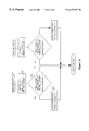
- FIG. 1 is a schematic representation of the network:
- FIGS. 2 a , 2 b and 2 c are flow diagrams showing data flow in a first method of routing
- FIGS. 3, 4 and 5 show data flow in a second method of routing:
- a typical “intelligent network” is shown schematically, with digital local exchanges (DLE) 1 each having connections to customers via local access links 3 .
- the DLEs 1 a , 1 b , 1 c and 1 d are fully interconnected by a trunk network having digital main switching units (DMSUs) 2 which are also referred to herein as service switching points ISSPs).
- DMSUs digital main switching units
- ISSPs service switching points
- SCP service control point
- SSP 2 may receive programmed trigger requirements in respect of information concerning the origin or destination of a call in progress. Such triggers result in the SSP communicating by way of signalling paths 9 with one of the network SCP 8 which provide instructions to the SSP for specialised handling of the particular call.
- C 7 (NUP) signalling provides for DPNSS signals to be transferred across the network.
- customer premises equipment (CPE) connected to the first PBX 22 may only require to dial a short code to indicate a connection is required to CPE connected to PBX 20 .
- Control means of the PBX 22 will cause the setting up of a call through the network by way of one of the connected DLEs 1 a , 1 b though the network to one of the DLEs 1 c , 1 d simply by providing to the DLE 1 a a destination telephone number.
- the DLE or the SSP 2 on detecting the origin of the call may cause automatic set up of a link through the network to the destination PBX.
- any failure of or congestion on the links 31 , 32 cannot be accommodated within the AAR or DAR schemes mentioned since the access signalling to the PBXs from the destination DLE results in calls being cleared on an end-to-end basis without the network being able to re-route the call.
- DPNSS access signalling under access link failure conditions transmits a congestion (CRM) message from the destination DLE using a C 7 (NUP) NEED signalling message.
- CCM congestion
- NUP C 7
- the SCP 8 when the SCP 8 is accessed by one of the SSPs 2 for routing information as part of the normal call set up in an intelligent network using a C 7 (INAP) IDP signalling message DAR, as previously discussed, is used for routing calls to the DLEs 1 c or 1 d .
- INAP C 7
- a route is selected either to the destination DLE 1 c or the destination DLE 1 D.
- the selected DLE ( 1 c or 1 d ) will be in accordance with a list in which one of the two possible DLEs is marked as a current routing choice.
- a further trigger is set at the SSP 2 indicating that any route select failure resulting in a C 7 (NUP) (nEED) message causes a route select failure report also to be sent to the SCP 8 .
- NUP C 7
- nEED route select failure report also to be sent to the SCP 8 .
- the SCP 8 receives a CRM message indicating that failure has occurred, it causes the other network address i.e. the DLE 1 d to be selected as current routing choice and subsequent calls will be routed to the DLE 1 d and thence to PBX 20 .
- Further refinement of the basic algorithm used to select the destination route includes providing counters within the SCP 8 which prevent or limit the rate at which cycling between potential alternative routes occurs in case failure of one of the links from a DLE 1 to PBX 20 , 22 results in congestion on the other link causing periodic C 7 CRM messages.
- FIGS. 2 to 5 show the programming language operators. The operators describe decision making criteria and changes to variables and for the avoidance of doubt have the following meanings
- the data table in respect of the destination PBX 20 (and for calls in the opposed direction for the PBX 22 as appropriate) has the following variables:
- a data table in respect of available routes is consulted in respect of the particular destination telephone number.
- the selection of route is described with reference to only a choice of two routes, that is to say via the DLE 1 c or via the DLE 1 d of FIG. 1, although it will be appreciated that the PBX 20 may be connected to more than two DLEs and a cycle pointer may be consulted.
- the currently selected cycle choice is considered to determine which is the preferred route for the current call.
- the choice flag is then reversed at step 215 or 220 in dependence upon the outcome of the interrogation at step 210 indicating the last route used.
- the current cycle choice is then used 230 to select from a data table the route through the network to the appropriate destination exchange either DLE 1 c or DLE 1 d and a timer started in the SCP.
- the selected route identity is now transferred 235 , 240 to the SSP 2 and a trigger set to respond to the SCP if a call failure (C 7 (NUP) NEED) signal is received.
- the SCP 8 determines that a successful call has occurred. Considering then if the timer set in the SCP 8 at step 230 expires without receipt of a C 7 (INAP) message from the SSP 2 indicating call failure then the SCP 8 assumes that the current call has been successfully set up between the PBX 22 and the PBX 20 .
- INAP C 7
- a successful call on route 1 results in the success 1 flag being set to 1, the count_pass_ 1 counter in respect of the successful route being incremented so that on the next application for routing information on route 1 the next network route is selected and finally the last counter appropriate to the route being reset to 0 since a successful call has occurred.
- the procedure shown in FIG. 2 c is followed.
- the route used is determined from the current route choice indicator (step not shown) and either the failed call route 1 or failed call route 2 flow is followed within the SCP 8 in dependence upon the route choice. This is believed sufficient to consider only the failed call route 1 flow and to note that if the current route choice was set at 2 the failed call route 2 tables will be used as shown in the right hand section of FIG. 2 c .
- the success 1 counter is set to 0, the last 1 counter is incremented by 1 and the failures 1 counter is incremented by 1.
- the last counter in respect of the alternative route (last_counter_ 2 ) is compared with the value of N to determine whether the other route has exceeded the maximum number of consecutive failed calls permissible under normal operating circumstances. If the last_counter_ 2 is less then the last threshold then the current route choice will be set to route 2 (step 280 ) so that the next call arriving at the SCP 8 will be directed to the alternative route and the failures counter 1 is reset. Resetting of failures counter 1 ensures that when congestion on route 2 has resulted in route 1 being sequentially selected because there have been more than N failures on route 2 the first route is used until it suffers M sequential failures. Now, provided that on the next application of a call to route 2 , route 2 succeeds then as indicated in FIG. 2 b at step 255 the last_counter_ 2 will be reset and the two routes will be alternately selected as previously.
- last_counter_ 1 will rapidly reach the last threshold N and calls will be sequentially routed to route 2 until congestions or route failure results in the failures to counter exceeding the failures threshold M.
- the SCP 8 uses current choice routes (route 1 , route 2 . . . route N) for a particular destination network address.
- route select failure occurs the next network address in the dynamic alternative routing list is selected and in this way the traffic stream is divided between routes.
- the system performs DAR in this manner unless the route to which it would change has had more than last threshold (N) consecutive call fails. If more than N call failures have occurred on the route to which route selected would change then the route selected stays until the failures threshold (M) for the first route is reached. If M failures occur on the first route then the system seeks to switch to alternate routing ignoring the last counter threshold.
- the SCP 8 is arranged to allocate traffic sequentially to the destination PBX by way of the DLEs 1 to which it is connected alternately.
- sequentially arriving calls will be routed in the form route A, route B, route A, route B, . . . unless or until a number of consecutive congestion messages are received.
- Once a specified number of congestion messages for a particular route have been received traffic is then allocated to the other route.
- the congestion threshold is set to three then traffic may be routed A, B, A, B A congested, B, A congested, B A congested, B, B, B . . . this will occur until congestion or route failure then occurs on the second route at which point sequential allocation of traffic is re-attempted.
- Use_A and use_B are mutually exclusive such that if one is set to 1 the otheris set to 0.
- a C 7 (INAP) message is sent to the SCP 8 and upon the call arrival the SCP 8 consults, at step 300 , the A_consec Counter to determine whether it is at the value set in the T 1 field for the maximum number of consecutive failed calls on the route. If A_consec counter does not equal T 1 then the SCP 8 steps to interrogate the B_consec counter at step 310 to determine whether B_consec is equal to T 1 and if not proceeds to the route select step at 320 .
- step 300 If at step 300 A_consec is equal to T 1 and A_lockout counter is equal to 0 then this would indicate that T 1 calls have failed consecutively in attempting to take the first selected route. Thus at step 305 the A_lockout counter is set to the value T 2 and the A_consec counter is set to 0.
- the A_lockout counter will be stepped down by one each time a call fails on the alternative failure route B. Note also that so long as the A_lockout counter has not been stepped to 0 step 305 is not reached.
- step 310 if T 1 calls have failed consecutively on the second route then the B_lockout counter is set to T 2 and the B_consec call counter is reset.
- step 320 if A_lockout is greater than 0 or the use_B flag is set to 1 then at step 325 routing information selected from the route table is returned to the SSP and the status of A_lockout counter determines the next macro function to be carried in the SCP 8 either on expiry of a time out period during which no failure message is returned to the SCP 8 or in the event of a failure on route B. Similarly, if use_B is not equal to 1 provided that A_lockout counter is at 0 then route A is used as the preferential route between the PBXs, and at step 330 a timer is commenced and routing instructions are returned to the SSP to cause the A route to be used.
- the SCP 8 follows the procedure shown in FIG. 4 .
- route B was used for the setting up of the call, if the A_lockout counter is equal to 0 then the use_A and use_B flags are toggled so that the next call will use route A. This is shown at step 335 .
- the B_consec counter is set to 0 regardless of its previous setting because a call on route B has now been successful as shown at step 340 .
- step 340 at which B_consec is reset to 0 is still followed.
- a successful call using route A will causing toggling of the A and B usage flags if B_lockout is equal to 0 and the A_consec counter will be reset to 0 at step 350 .
- step 365 the B_consec counter is set to 0 even though the call has failed and the A_lockout counter is decremented. This ensures that route B will continue to be used until T 2 calls on a route B have failed before any attempts is made to re-use route A following its previous failure.
- step 370 if the A_lockout counter has reached 0 then the use_A and use_B flags are toggled (step 375 ) so that the next call arrival will at step 320 be directed to route A.
- route B will quickly reach the lockout condition and calls will then solely be offered to route A until such time as T 2 failures of route A occur.
- B_lockout counter is not equal to 0 then A_consec is forced to 0 B_lockout is decremented at step 380 and at step 385 , unless B_lockout as reached 0, the use_A flag remains set.
- step 390 the use_A and use_B flags are toggled so that the next call isoffered to route B and then calls alternate between the routes. If both routes are in failure mode calls will continue to be offered alternately to the routes until either A_consec or B_consec equals t 1 . When either counter equals t 1 then calls are offered to the other route until t 2 calls on that route fail when consecutive calls are again shared between the routes.
- the A_lockout counter will be set to T 2 at step 305 .
- a high security virtual private network utilising the PSTN can be provided.
- any destination PBX may be provided with connections to multiple destination telephone exchanges whereby any calls to the telephone number allocated to that PBX may be direct alternately through the destination exchanges. It will also be appreciated that the system may be expanded to allow connection to more than two local exchanges and may also be used to provide secure connection for any customer equipment capable of connection to a plurality of lines.
- the locking out of failed routes may require multiple comparative lockout counters to be used.
- A_lockout(B), A_lockout(C) and A_lockout(D) which will be respectively decremented when calls on routes B,C and D fail.
- A may remain locked out until all three counters reach zero.
- Another method of operation may use a single lockout counter which is decremented each time a call fails on any other route.
- the re-instatement of a failed route may not be dependent upon calls failing on other routes but may be a lockout for a pre-determined period of time after which calls may again be offered to the route, each route being locked out on consecutive or proportionate failure (subject to other routes remaining available).
- calls may be offered to a previously locked out route after a predetermined number of calls overall have been offered for connection through the network to the PBX.
- lockout of a route may not be based entirely on consecutive call failures. For instance, it is possible to use a thresholding system whereby if x of the most recent y calls have failed (notwithstanding say fail, success, fail, fail, success, fail) for example the route is not attempted for a period of time, or until other routes have failed or until a specxified number of calls have been offered through the network.
Applications Claiming Priority (3)
| Application Number | Priority Date | Filing Date | Title |
|---|---|---|---|
| EP96309427 | 1996-12-20 | ||
| EP96309427 | 1996-12-20 | ||
| PCT/GB1997/003357 WO1998028924A1 (en) | 1996-12-20 | 1997-12-04 | Telecommunications network |
Publications (1)
| Publication Number | Publication Date |
|---|---|
| US6377677B1 true US6377677B1 (en) | 2002-04-23 |
Family
ID=8225206
Family Applications (1)
| Application Number | Title | Priority Date | Filing Date |
|---|---|---|---|
| US09/068,229 Expired - Fee Related US6377677B1 (en) | 1996-12-20 | 1997-12-04 | Telecommunications network having successively utilized different network addresses to a single destination |
Country Status (5)
| Country | Link |
|---|---|
| US (1) | US6377677B1 (de) |
| EP (1) | EP0948868A1 (de) |
| JP (1) | JP2001507187A (de) |
| AU (1) | AU5402698A (de) |
| WO (1) | WO1998028924A1 (de) |
Cited By (11)
| Publication number | Priority date | Publication date | Assignee | Title |
|---|---|---|---|---|
| US6480595B1 (en) * | 1998-01-30 | 2002-11-12 | Nec Corporation | Method of communication through leased line in virtual private network |
| US20030016808A1 (en) * | 2000-12-26 | 2003-01-23 | Nortel Networks Limited | Dynamic adaptation to congestion in connection-oriented networks |
| US6704406B1 (en) * | 2001-05-29 | 2004-03-09 | Cisco Technology, Inc. | Automated route plan generation |
| WO2004023719A2 (en) * | 2002-09-09 | 2004-03-18 | Sheer Networks Inc. | Root cause correlation in connectionless networks |
| US20050117599A1 (en) * | 2003-11-28 | 2005-06-02 | Kabushiki Kaisha Toshiba | Network telephone system, main apparatus for the same system and connection information update method using the same system |
| US6975717B1 (en) * | 2003-03-13 | 2005-12-13 | Vulcan Research LLC | Selective processing of calls using alternative network telephony |
| US6980638B1 (en) * | 2003-03-13 | 2005-12-27 | Vulcan Research LLC | Failsafe configuration for alternative network telephony |
| US20060183472A1 (en) * | 2005-02-17 | 2006-08-17 | Nookala Sriram N | Control of data call origination based on prior origination attempts |
| KR100721646B1 (ko) | 2004-04-23 | 2007-05-23 | 가부시키가이샤 소니 컴퓨터 엔터테인먼트 | 합성가능 파이프라인 제어를 위한 방법들 및 장치 |
| US7793165B1 (en) * | 2007-09-11 | 2010-09-07 | Sprint Communications Company L.P. | Selecting an address provider using a failover counter |
| US20150121473A1 (en) * | 2013-10-31 | 2015-04-30 | Telefonica Digital Espana, S.L.U. | Method and system for providing multipath tcp proxy services |
Families Citing this family (2)
| Publication number | Priority date | Publication date | Assignee | Title |
|---|---|---|---|---|
| US6760766B1 (en) | 1998-08-21 | 2004-07-06 | Per Sahlqvist | Data transmission method and device |
| GB0112955D0 (en) | 2001-05-29 | 2001-07-18 | Marconi Comm Ltd | A route selector and a method of signal routing |
Citations (5)
| Publication number | Priority date | Publication date | Assignee | Title |
|---|---|---|---|---|
| US5317566A (en) * | 1993-08-18 | 1994-05-31 | Ascom Timeplex Trading Ag | Least cost route selection in distributed digital communication networks |
| WO1996011551A1 (en) * | 1994-10-10 | 1996-04-18 | British Telecommunications Public Limited Company | Communications traffic management arrangement |
| US5526414A (en) * | 1994-10-26 | 1996-06-11 | Northern Telecom Limited | Dynamically controlled routing using virtual nodes |
| US5715304A (en) * | 1992-12-17 | 1998-02-03 | Kabushiki Kaisha Toshiba | Private branch exchange |
| US5838769A (en) * | 1996-12-31 | 1998-11-17 | Mci Communications Corporation | Method of reducing risk that calls are blocked by egress switch or trunk failures |
Family Cites Families (1)
| Publication number | Priority date | Publication date | Assignee | Title |
|---|---|---|---|---|
| US5086460A (en) * | 1990-04-02 | 1992-02-04 | At&T Bell Laboratories | Communications system ingress and egress arrangement |
-
1997
- 1997-12-04 WO PCT/GB1997/003357 patent/WO1998028924A1/en not_active Application Discontinuation
- 1997-12-04 JP JP52850598A patent/JP2001507187A/ja active Pending
- 1997-12-04 US US09/068,229 patent/US6377677B1/en not_active Expired - Fee Related
- 1997-12-04 AU AU54026/98A patent/AU5402698A/en not_active Abandoned
- 1997-12-04 EP EP97947783A patent/EP0948868A1/de not_active Withdrawn
Patent Citations (5)
| Publication number | Priority date | Publication date | Assignee | Title |
|---|---|---|---|---|
| US5715304A (en) * | 1992-12-17 | 1998-02-03 | Kabushiki Kaisha Toshiba | Private branch exchange |
| US5317566A (en) * | 1993-08-18 | 1994-05-31 | Ascom Timeplex Trading Ag | Least cost route selection in distributed digital communication networks |
| WO1996011551A1 (en) * | 1994-10-10 | 1996-04-18 | British Telecommunications Public Limited Company | Communications traffic management arrangement |
| US5526414A (en) * | 1994-10-26 | 1996-06-11 | Northern Telecom Limited | Dynamically controlled routing using virtual nodes |
| US5838769A (en) * | 1996-12-31 | 1998-11-17 | Mci Communications Corporation | Method of reducing risk that calls are blocked by egress switch or trunk failures |
Non-Patent Citations (1)
| Title |
|---|
| Dynamic Network Evolution With Examples from AT&T's Evolving Dynamic Network, IEEE Communications Magazine, vol. 33, No. 7, Jul. 1, 1995, pp. 26-39. * |
Cited By (21)
| Publication number | Priority date | Publication date | Assignee | Title |
|---|---|---|---|---|
| US6480595B1 (en) * | 1998-01-30 | 2002-11-12 | Nec Corporation | Method of communication through leased line in virtual private network |
| US20030016808A1 (en) * | 2000-12-26 | 2003-01-23 | Nortel Networks Limited | Dynamic adaptation to congestion in connection-oriented networks |
| US7127056B2 (en) * | 2000-12-26 | 2006-10-24 | Nortel Networks Limited | Dynamic adaptation to congestion in connection-oriented networks |
| US6704406B1 (en) * | 2001-05-29 | 2004-03-09 | Cisco Technology, Inc. | Automated route plan generation |
| US6975718B1 (en) | 2001-05-29 | 2005-12-13 | Cisco Technology, Inc. | Automated route plan generation |
| US20060095815A1 (en) * | 2002-09-09 | 2006-05-04 | Ariel Noy | Root cause correlation in connectionless networks |
| WO2004023719A2 (en) * | 2002-09-09 | 2004-03-18 | Sheer Networks Inc. | Root cause correlation in connectionless networks |
| WO2004023719A3 (en) * | 2002-09-09 | 2004-05-06 | Sheer Networks Inc | Root cause correlation in connectionless networks |
| US7373563B2 (en) * | 2002-09-09 | 2008-05-13 | Sheer Networks Inc. | Root cause correlation in connectionless networks |
| EP1953962A1 (de) * | 2002-09-09 | 2008-08-06 | Cisco Technology, Inc. | Grundursachenkorrelation in verbindungslosen Netzen |
| US6975717B1 (en) * | 2003-03-13 | 2005-12-13 | Vulcan Research LLC | Selective processing of calls using alternative network telephony |
| US20060029204A1 (en) * | 2003-03-13 | 2006-02-09 | Vulcan Research LLC | Selective processing of calls using alternative network telephony |
| US20060013379A1 (en) * | 2003-03-13 | 2006-01-19 | Vulcan Research LLC | Failsafe configuration for alternative network telephony |
| US6980638B1 (en) * | 2003-03-13 | 2005-12-27 | Vulcan Research LLC | Failsafe configuration for alternative network telephony |
| US7206399B2 (en) * | 2003-03-13 | 2007-04-17 | Vulcan Patents Llc | Failsafe configuration for alternative network telephony |
| US20050117599A1 (en) * | 2003-11-28 | 2005-06-02 | Kabushiki Kaisha Toshiba | Network telephone system, main apparatus for the same system and connection information update method using the same system |
| KR100721646B1 (ko) | 2004-04-23 | 2007-05-23 | 가부시키가이샤 소니 컴퓨터 엔터테인먼트 | 합성가능 파이프라인 제어를 위한 방법들 및 장치 |
| US20060183472A1 (en) * | 2005-02-17 | 2006-08-17 | Nookala Sriram N | Control of data call origination based on prior origination attempts |
| US8660527B2 (en) * | 2005-02-17 | 2014-02-25 | Qualcomm Incorporated | Control of data call origination based on prior origination attempts |
| US7793165B1 (en) * | 2007-09-11 | 2010-09-07 | Sprint Communications Company L.P. | Selecting an address provider using a failover counter |
| US20150121473A1 (en) * | 2013-10-31 | 2015-04-30 | Telefonica Digital Espana, S.L.U. | Method and system for providing multipath tcp proxy services |
Also Published As
| Publication number | Publication date |
|---|---|
| WO1998028924A1 (en) | 1998-07-02 |
| JP2001507187A (ja) | 2001-05-29 |
| EP0948868A1 (de) | 1999-10-13 |
| AU5402698A (en) | 1998-07-17 |
Similar Documents
| Publication | Publication Date | Title |
|---|---|---|
| CA1284204C (en) | Routing of network traffic | |
| EP0764383B1 (de) | Verkehrsvermittlung in einem verbesserten integrierten netzwerk | |
| EP0631447B1 (de) | Telekommunikationsnetzwerkarchitektur und System | |
| CA1253241A (en) | Automatic call distributor telephone service | |
| US5450482A (en) | Dynamic network automatic call distribution | |
| US5615254A (en) | Methods and systems for dynamic routing in a switched comunication network | |
| US6377677B1 (en) | Telecommunications network having successively utilized different network addresses to a single destination | |
| US5778057A (en) | Service control point congestion control method | |
| US6330323B1 (en) | Enhanced overflow call processing | |
| US5825860A (en) | Load sharing group of service control points connected to a mediation point for traffic management control | |
| US5838769A (en) | Method of reducing risk that calls are blocked by egress switch or trunk failures | |
| US5719930A (en) | Method of volume screening signalling messages in a telecommunication system | |
| US6473402B1 (en) | Communications link interconnecting service control points of a load sharing group for traffic management control | |
| WO1996011551A1 (en) | Communications traffic management arrangement | |
| AU732290B2 (en) | Method for controlling a call | |
| CA2293697A1 (en) | Overload prevention in a service control point (scp) | |
| CA2237623C (en) | Load sharing group of service control points connected to a mediation point for traffic management control | |
| Bodzik et al. | Fossil1: a policy analysis model of the US energy transition | |
| WO1998019468A1 (en) | Communications link interconnecting service control points of a load sharing group for traffic management control | |
| Wang | Support of mechanized link dimensioning in the common channel signaling networks |
Legal Events
| Date | Code | Title | Description |
|---|---|---|---|
| AS | Assignment |
Owner name: BRITISH TELECOMMUNICATIONS PUBLIC LIMITED COMPANY, Free format text: ASSIGNMENT OF ASSIGNORS INTEREST;ASSIGNORS:ACKERLEY, ROGER G.;KEY, PETER B.;WOOLLEY, MARK;REEL/FRAME:009887/0968 Effective date: 19980202 |
|
| FPAY | Fee payment |
Year of fee payment: 4 |
|
| REMI | Maintenance fee reminder mailed | ||
| LAPS | Lapse for failure to pay maintenance fees | ||
| STCH | Information on status: patent discontinuation |
Free format text: PATENT EXPIRED DUE TO NONPAYMENT OF MAINTENANCE FEES UNDER 37 CFR 1.362 |
|
| FP | Lapsed due to failure to pay maintenance fee |
Effective date: 20100423 |