US6371663B1 - Multichannel optical module - Google Patents
Multichannel optical module Download PDFInfo
- Publication number
- US6371663B1 US6371663B1 US09/617,650 US61765000A US6371663B1 US 6371663 B1 US6371663 B1 US 6371663B1 US 61765000 A US61765000 A US 61765000A US 6371663 B1 US6371663 B1 US 6371663B1
- Authority
- US
- United States
- Prior art keywords
- connector
- module
- transducers
- connection port
- holding sleeve
- Prior art date
- Legal status (The legal status is an assumption and is not a legal conclusion. Google has not performed a legal analysis and makes no representation as to the accuracy of the status listed.)
- Expired - Fee Related
Links
Images


Classifications
-
- G—PHYSICS
- G02—OPTICS
- G02B—OPTICAL ELEMENTS, SYSTEMS OR APPARATUS
- G02B6/00—Light guides; Structural details of arrangements comprising light guides and other optical elements, e.g. couplings
- G02B6/24—Coupling light guides
- G02B6/42—Coupling light guides with opto-electronic elements
- G02B6/4292—Coupling light guides with opto-electronic elements the light guide being disconnectable from the opto-electronic element, e.g. mutually self aligning arrangements
-
- G—PHYSICS
- G02—OPTICS
- G02B—OPTICAL ELEMENTS, SYSTEMS OR APPARATUS
- G02B6/00—Light guides; Structural details of arrangements comprising light guides and other optical elements, e.g. couplings
- G02B6/24—Coupling light guides
- G02B6/42—Coupling light guides with opto-electronic elements
- G02B6/4201—Packages, e.g. shape, construction, internal or external details
- G02B6/4246—Bidirectionally operating package structures
-
- G—PHYSICS
- G02—OPTICS
- G02B—OPTICAL ELEMENTS, SYSTEMS OR APPARATUS
- G02B6/00—Light guides; Structural details of arrangements comprising light guides and other optical elements, e.g. couplings
- G02B6/24—Coupling light guides
- G02B6/42—Coupling light guides with opto-electronic elements
- G02B6/4201—Packages, e.g. shape, construction, internal or external details
- G02B6/4249—Packages, e.g. shape, construction, internal or external details comprising arrays of active devices and fibres
-
- G—PHYSICS
- G02—OPTICS
- G02B—OPTICAL ELEMENTS, SYSTEMS OR APPARATUS
- G02B6/00—Light guides; Structural details of arrangements comprising light guides and other optical elements, e.g. couplings
- G02B6/24—Coupling light guides
- G02B6/36—Mechanical coupling means
- G02B6/38—Mechanical coupling means having fibre to fibre mating means
- G02B6/3807—Dismountable connectors, i.e. comprising plugs
- G02B6/389—Dismountable connectors, i.e. comprising plugs characterised by the method of fastening connecting plugs and sockets, e.g. screw- or nut-lock, snap-in, bayonet type
- G02B6/3893—Push-pull type, e.g. snap-in, push-on
Definitions
- the invention lies in the field of electrooptical data transmission.
- transmitting and/or receiving units which are generally also denoted as electrooptical modules.
- the modules convert electrical signals into optical signals and/or optical into electrical signals.
- the actual signal conversion is effected by electrooptical transducers which can, for example, be constructed as laser diodes (transmitters) or photodiodes (receivers) and in each case have transducer surfaces which are also denoted as optically active zones.
- the modules can be equipped with mechanical coupling devices for alignment with and mechanical connection to an optical conductor connector.
- Those coupling devices will be referred to below as connection ports or receptacles.
- optical conductor is to be understood within the framework of the present invention to include all elements such as, for example, glass fibers or plastic fibers which are suitable for directional relaying of optical waves.
- the connector pins are constructed as standardized pins (ferrules) and in each case hold in a central longitudinal bore a single optical conductor which terminates at the connector pin end face.
- the centered optical conductor guidance does not require rotary alignment or fixing of the connector pin.
- the holding sleeve and the mechanical lock are configured in accordance with the Japanese Industry Standard JIS-C-5973-1990.
- this standard stipulates the length and the diameter of the connector pin, the connector housing dimensions and the position and shape of the shaped elements which cooperate with the mechanical lock of the connection port.
- SC connector A connection port constructed for coupling to such an SC connector is therefore denoted as an SC connection port or SC receptacle.
- each transmission channel there is thus provided for each transmission channel a separate SC connection port with the aid of which in each case a single electrooptical transducer transmits over a waveguide into the optical conductor end face (transmitter) and receives radiation emitted from the end face (receiver).
- a further possibility is to develop special forms of plugs.
- a plurality of electrooptical transducers are assigned to a connection port.
- the connection port serves to hold and lock a plug which contains a plurality of optical conductors.
- the transducers are aligned next to one another with a coupling plane running perpendicular to the plugging direction.
- the connection port has a holder for the plug and locking elements cooperating mechanically with the plug.
- the holder is simultaneously constructed as an alignment aid which cooperates with a corresponding configuration of the plug in such a way that in each case a transducer can be individually coupled to an end of one of the optical conductors in the region of the coupling plane.
- the mutual alignment of the connection port and plug is performed via self-closure of the plug in the holder.
- the plug Upon making contact with the light entry and/or light exit surfaces of the waveguides, the plug cannot fall back axially. In the case of frequent plugging cycles, in particular, the end faces of the optical conductor ends are therefore subjected to an increased risk of damage (see published European patent application EP 0 618 468 A1).
- the object of the invention is to provide a multichannel optical module which overcomes the above-noted deficiencies and disadvantages of the prior art devices and methods of this kind, and which, in conjunction with a substantially reduced space requirement or substantially increased module functionality/number of channels can continue to be handled in the accustomed way and can easily be coupled, as before, to the optical conductors to be connected.
- a multichannel optical module for receiving a connector of the type having a connector housing with shaped elements and a substantially cylindrical connector pin in the housing with a plurality of optical conductors arranged in a central longitudinal plane, the module comprising:
- a housing formed with a connection port for receiving a connector along a plug-in direction and locking the connector therein;
- connection port a plurality of electrooptical transducers assigned to the connection port, the transducers being optically aligned via waveguides next to one another with a coupling plane oriented perpendicular to the plug-in direction;
- connection port having a cylindrical holding sleeve for a connector pin of the connector, and locking elements cooperating mechanically with shaped elements of the connector housing;
- alignment aids formed on the holding sleeve for mutually aligning the connection port and the connector pin of the connector, the alignment aids cooperating with corresponding alignments aids on the connector pin such that in the region of the coupling plane are respective the transducer is coupled individually to an end of a respective one of the optical conductors;
- the waveguides extending in a common coupling member and spreading open toward the transducers.
- the alignments aids are longitudinal webs or ribs constructed on the inside of the holding sleeve.
- the holding sleeve has a defined longitudinal axis and the alignment aids are centering pins arranged on both sides of the longitudinal axis of the holding sleeve.
- the solution essentially provides to configure the connection port in a way known per se such that a connector pin which contains a plurality of optical conductors can be held and, in so doing, to ensure in a novel way the centering between the plug and connection port by means of a cylindrical configuration previously customary only for single-pole plugs, and to provide the interlocking cylindrical components with appropriate alignment aids for the purpose of defined alignment of the waveguides and the optical conductors to be coupled, the waveguides via which the transducers are aligned with a coupling plane running in a common coupling member which spreads open the course of the waveguide on the transducer side.
- alignment aids is to be understood as all components which recognizably fulfill for the person skilled in the art the aim of mutual positioning with corresponding geometries of the connector.
- Members with elongated geometries in particular prove to be suitable alignment aids, for example cylindrical pins, pins or rods having a polygonal cross section, or bolts which are arranged on both sides of the longitudinal axis of the holding sleeve, or else longitudinal webs or longitudinal ribs which are constructed on the inside of the holding sleeve.
- a substantial advantageous aspect of the module according to the invention consists in that it is possible to couple a plurality of optical conductor ends with the aid of a single connection port. It is particularly advantageous in this case that because of the configuration of the connection port in accordance with an SC connector the optical conductors can be coupled in the previously customary and controlled way to the module and/or to the optical transducers contained therein.
- the module according to the invention therefore departs from the avenue of continuous miniaturization in conjunction with retaining the principle of the previous basic design, and turns, rather, to a new connection arrangement and connection configuration using the principle of the SC connection.
- a single connection port can be used to couple a plurality of optical conductor ends, which permits the module functionality to be doubled or multiplied without changing the housing design. Consequently, it is possible either to reduce the design by a factor of at least 2—that is to say at least to halve the required housing basic area in order to implement a so-called small form factor (SFF) module—or correspondingly to increase the packing density or the number of channels.
- SFF small form factor
- the connector terminates two or four optical conductors at the end.
- the module has two or four transducers. The invention permits a further spacing-apart of the transducers than is provided by the lateral spacing of the optical conductor ends.
- the transducers are vertically emitting laser transmitters.
- the lasers preferably transmit at an emission wavelength of 850 nm or 1300 nm. This is particularly advantageous from a design point of view. This permits, for example, an up-ended arrangement of printed circuit boards carrying a plurality of transducers in each case, the transducers preferably being situated with their optically active zones opposite.
- a module assembly comprising two of the above-outlined modules.
- the transducers in one of the modules are transmitters, and the transducers of the other module are receivers.
- the common housing has a base area not exceeding 26 mm*40 mm, preferably not exceeding 25.40 mm*39.12 mm.
- the module according to the invention is preferably applied in module arrangements having two or more modules.
- the previously customary size of module housing of the transceiver described at the beginning can advantageously be retained, a doubling or multiplying of the channel capacity being achieved in accordance with the number of the optical conductor ends respectively guided parallel to one of the connection ports.
- one of the modules can be fitted with transducers constructed as transmitters, and the other module is fitted with transducers constructed as receivers.
- the module arrangement can preferably have the two modules in one common housing whose base area does not fall below 26 mm ⁇ 40 mm, preferably 25.40 mm ⁇ 39.12 mm.
- FIG. 1 is a perspective view of a module with an opposite connector as coupling partner
- FIG. 2 is an enlarged view of a portion of FIG. 1 of the region between the connector end face and the module;
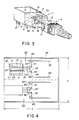
- FIG. 3 is perspective view which is reversed relative to FIG. 1 and which shows the module from the rear;
- FIG. 4 is a plan view of a module configuration according to the invention.
- FIGS. 1 to 3 show the connector shortly before being completely inserted into the connection port.
- a multichannel optical module having a connection port 1 which, with regard to its essential dimensions (in particular with reference to a mechanical lock 2 and a holding sleeve 4 ), is constructed as a complementary SC receptacle for holding an SC connector in accordance with the Japanese Industry Standard JIS-C-5973-1999. Reference is hereby expressly made to Industry Standard JIS-C-5973-1990.
- the mechanical lock 2 comprises two locking arms 5 , 6 , which latch with locking noses 5 a , 6 a into corresponding undercuts 8 , 9 of a connector housing 10 when the connector is introduced completely into the connection port 1 .
- the module also comprises a housing 11 and a plurality of electrical connecting contacts 12 , which can be arranged, for example, in two rows of 5 contacts each, or in another way (for example 1*9 or 2*10).
- the holding sleeve 4 is provided on the inside with longitudinal elevations, for example in the form of longitudinal webs or longitudinal ribs 14 , 15 , which point in the radial direction toward the longitudinal axis A of the holding sleeve 4 .
- the longitudinal webs 14 , 15 serve as alignment aids which cooperate with longitudinal grooves or ridges 20 , 21 constructed opposite on the circumference of a connector pin 18 (FIGS. 1 and 2 ).
- the cooperation of the alignment aids 14 , 15 and 20 , 21 ensures that a central longitudinal plane 24 including the connector pin longitudinal axis A is aligned in a defined position with reference to the module as soon as the connector pin 18 is inserted into the holding sleeve 4 .
- alignments aids for example, the sleeve can have centering pins which are arranged in a plane 24 on both sides of its longitudinal axis and cooperate with suitable grooves or bores in the connector pin 18 .
- a plurality of electrooptical transducers 26 , 28 are arranged in the module housing 11 .
- the transducers can be laser diodes which emit light with a wavelength of 850 nm or 1300 nm. In the exemplary embodiment according to FIG. 1, only two transducers are shown, by way of example.
- the transducers 26 , 28 or their optical active zones are projected via a coupling member 30 onto a cross sectional plane, which coincides with the end face of the plugged-in connector pin 18 , in such a way that waveguides 31 , 32 run between the transducers 26 , 28 and the ends 40 , 42 of two optical conductors 43 , 44 arranged jointly in the plane 24 .
- a likewise suitable coupling member is disclosed in the commonly assigned, copending application Ser. No. 09/509,436 (see PCT publication WO 99/15927), the disclosure of which is herewith incorporated by reference. It is also possible, for example, for four optical conductors to be arranged in the plane 24 and to terminate at the end face 45 of the connector pin 18 .
- the module therefore provides a plurality of separate data transmission channels which can be coupled to separate and individual optical conductor ends which are arranged in a common SC connector.
- FIG. 4 shows a module assembly in which two modules 50 , 52 according to the invention are accommodated in a common housing 54 , which is illustrated as open.
- FIG. 4 illustrates in a greatly simplified and diagrammatic fashion only the parts of the module assembly which are particularly important for the following explanation.
- the module 50 contains two printed circuit boards 55 , 56 on which one control circuit each for two laser arrays 58 , 59 is placed.
- the laser arrays 58 , 59 are constructed as surface emitting lasers (so-called vertically emitting lasers/VCSEL).
- the beam path runs via waveguides 60 to 63 partially through a common coupling member 65 , and is deflected in each case at a mirror surface. As illustrated in outline, the coupling member 65 spreads open the course of the path on the transducer side, the result being to obtain more design space and spacing between the printed circuit boards 55 , 56 .
- the waveguides 60 to 63 image the active zones of the individual lasers on a common coupling plane 70 in which the end faces of four optical conductor ends, which are illustrated in outline and run in the connector pin 18 ′ are situated.
- the connector pin 18 ′ is situated with its face on a stop surface.
- alignment aids, on the connection port side, in the form of centering pins 72 , 73 can be detected in outline along the connector pin 18 ′.
- the electrooptical transducers are constructed in the case of module 52 as receiving arrays 84 , 85 which each have a plurality (for example 2) of photosensitive zones.
- the beam path or the waveguides 80 , 82 otherwise run in a way previously described via a common coupling member 87 .
- the module arrangement according to FIG. 4 therefore respectively has four transmitting or receiving channels in a design size which corresponds to conventional transceiver housings with only one separate receiving channel and one separate transmitting channel.
- the coupling to the module arrangement can advantageously be performed by means of so-called SC-DC (Dual Connector) or SC-QC (Quadruple Connector) connectors, each connector corresponding as regards its essential dimensions and locking mechanisms to the above-mentioned SC standard, and terminating the optical conductors respectively running in a common plane.
- SC-DC Dual Connector
- SC-QC Quadrature Connector
Applications Claiming Priority (3)
| Application Number | Priority Date | Filing Date | Title |
|---|---|---|---|
| DE19802190 | 1998-01-16 | ||
| DE19802190A DE19802190C1 (de) | 1998-01-16 | 1998-01-16 | Mehrkanaliges optisches Modul |
| PCT/DE1999/000176 WO1999036819A1 (de) | 1998-01-16 | 1999-01-15 | Mehrkanaliges optisches modul |
Related Parent Applications (1)
| Application Number | Title | Priority Date | Filing Date |
|---|---|---|---|
| PCT/DE1999/000176 Continuation WO1999036819A1 (de) | 1998-01-16 | 1999-01-15 | Mehrkanaliges optisches modul |
Publications (1)
| Publication Number | Publication Date |
|---|---|
| US6371663B1 true US6371663B1 (en) | 2002-04-16 |
Family
ID=7855262
Family Applications (1)
| Application Number | Title | Priority Date | Filing Date |
|---|---|---|---|
| US09/617,650 Expired - Fee Related US6371663B1 (en) | 1998-01-16 | 2000-07-17 | Multichannel optical module |
Country Status (5)
| Country | Link |
|---|---|
| US (1) | US6371663B1 (de) |
| EP (1) | EP1062535B1 (de) |
| JP (1) | JP3546182B2 (de) |
| DE (2) | DE19802190C1 (de) |
| WO (1) | WO1999036819A1 (de) |
Cited By (18)
| Publication number | Priority date | Publication date | Assignee | Title |
|---|---|---|---|---|
| US20020030872A1 (en) * | 1999-05-27 | 2002-03-14 | Edwin Dair | Method and apparatus for multiboard fiber optic modules and fiber optic module arrays |
| US20020033979A1 (en) * | 1999-05-27 | 2002-03-21 | Edwin Dair | Method and apparatus for multiboard fiber optic modules and fiber optic module arrays |
| US6793412B2 (en) * | 2000-12-20 | 2004-09-21 | The Furukawa Electric Co., Ltd. | Optical connector having a light emitting element and a convergent lens |
| US20040235581A1 (en) * | 2003-04-01 | 2004-11-25 | Citron Lowell A. | Golf posture brace and garment |
| US20050135756A1 (en) * | 2003-12-19 | 2005-06-23 | Chao Zhang | Bi-directional optical transceiver module having automatic-restoring unlocking mechanism |
| US20050226626A1 (en) * | 2004-04-01 | 2005-10-13 | Chao Zhang | Small form factor pluggable optical transceiver having automatic-restoring unlocking mechanism and mechanism for locating optical transceiver components |
| US20050259994A1 (en) * | 2004-05-20 | 2005-11-24 | Chao Zhang | Optical transceiver module having improved printed circuit board |
| US20050271333A1 (en) * | 2004-06-04 | 2005-12-08 | Industrial Technology Research Institute | Light transceiver module |
| US20060013540A1 (en) * | 2004-07-19 | 2006-01-19 | Chao Zhang | Single fiber optical transceiver module |
| US20060133743A1 (en) * | 2004-12-22 | 2006-06-22 | Nelson Diaz | Planar decoupling in optical subassembly |
| US20060133744A1 (en) * | 2004-12-22 | 2006-06-22 | Nelson Diaz | Optical transciever with capacitive coupled signal ground with chassis ground |
| US20060208180A1 (en) * | 2005-03-17 | 2006-09-21 | Chao Zhang | Apparatus for measuring photo diodes' temperature dependence |
| US7153043B1 (en) | 2006-01-19 | 2006-12-26 | Fiberxon, Inc. | Optical transceiver having improved printed circuit board |
| US20070269217A1 (en) * | 2005-10-25 | 2007-11-22 | Rangchen Yu | Multi-Data-Rate Optical Transceiver |
| US20080124088A1 (en) * | 2006-11-27 | 2008-05-29 | Zhong Yang | Optical transceiver having improved unlocking mechanism |
| US20110123740A1 (en) * | 2009-11-20 | 2011-05-26 | Fih (Hong Kong) Limited | Method for making device housing, and device housing |
| US20170181604A1 (en) * | 2014-03-17 | 2017-06-29 | Intuitive Surgical Operations, Inc. | Multi-stage instrument connector |
| USD1013638S1 (en) * | 2021-08-27 | 2024-02-06 | A.J.World Co., Ltd. | Optical fiber connector |
Citations (13)
| Publication number | Priority date | Publication date | Assignee | Title |
|---|---|---|---|---|
| US4279465A (en) | 1979-11-30 | 1981-07-21 | The Singer Company | Device for transmitting and receiving optical data on the same optical transmission line |
| EP0226274A2 (de) | 1985-11-29 | 1987-06-24 | The Furukawa Electric Co., Ltd. | Mehrfachanordnung von optischen Fasern in optischen Steckern |
| US4895425A (en) * | 1988-02-26 | 1990-01-23 | Nippon Telegraph And Telephone Corporation | Plug-in optical fiber connector |
| US5028110A (en) | 1982-11-29 | 1991-07-02 | Adc Telecommunications, Inc. | Fiber optical component |
| US5093881A (en) | 1989-10-17 | 1992-03-03 | Societa' Cavi Pirelli S.P.A. | Connector for interconnecting optical fiber cable ribbons |
| US5230030A (en) | 1992-04-24 | 1993-07-20 | Motorola, Inc. | Interface coupling electronic circuitry |
| US5325454A (en) * | 1992-11-13 | 1994-06-28 | International Business Machines, Corporation | Fiber optic connector housing |
| EP0613032A2 (de) | 1993-02-23 | 1994-08-31 | The Whitaker Corporation | Faseroptische Kopplungseinrichtung |
| EP0618468A1 (de) | 1993-03-29 | 1994-10-05 | Motorola, Inc. | Eine Schnittstelle zum Koppeln von optischen Fasern mit elektronischen Schaltungen |
| US5473716A (en) | 1994-08-29 | 1995-12-05 | Motorola, Inc. | Fiber bundle interconnect and method of making same |
| US5528408A (en) | 1994-10-12 | 1996-06-18 | Methode Electronics, Inc. | Small footprint optoelectronic transceiver with laser |
| US5577146A (en) | 1992-07-14 | 1996-11-19 | Hewlett-Packard Company | Optical connectors |
| US5940561A (en) * | 1997-04-23 | 1999-08-17 | Siecor Corporation | Adapter assembly for precise alignment of fiber optic connectors |
-
1998
- 1998-01-16 DE DE19802190A patent/DE19802190C1/de not_active Expired - Fee Related
-
1999
- 1999-01-15 EP EP99907275A patent/EP1062535B1/de not_active Expired - Lifetime
- 1999-01-15 WO PCT/DE1999/000176 patent/WO1999036819A1/de active IP Right Grant
- 1999-01-15 DE DE59901190T patent/DE59901190D1/de not_active Expired - Fee Related
- 1999-01-15 JP JP2000540473A patent/JP3546182B2/ja not_active Expired - Fee Related
-
2000
- 2000-07-17 US US09/617,650 patent/US6371663B1/en not_active Expired - Fee Related
Patent Citations (14)
| Publication number | Priority date | Publication date | Assignee | Title |
|---|---|---|---|---|
| US4279465A (en) | 1979-11-30 | 1981-07-21 | The Singer Company | Device for transmitting and receiving optical data on the same optical transmission line |
| US5028110A (en) | 1982-11-29 | 1991-07-02 | Adc Telecommunications, Inc. | Fiber optical component |
| EP0226274A2 (de) | 1985-11-29 | 1987-06-24 | The Furukawa Electric Co., Ltd. | Mehrfachanordnung von optischen Fasern in optischen Steckern |
| US4895425A (en) * | 1988-02-26 | 1990-01-23 | Nippon Telegraph And Telephone Corporation | Plug-in optical fiber connector |
| US5093881A (en) | 1989-10-17 | 1992-03-03 | Societa' Cavi Pirelli S.P.A. | Connector for interconnecting optical fiber cable ribbons |
| EP0566900A1 (de) | 1992-04-24 | 1993-10-27 | Motorola, Inc. | Schnittstelle zur Kopplung von elektronischen Schaltungen |
| US5230030A (en) | 1992-04-24 | 1993-07-20 | Motorola, Inc. | Interface coupling electronic circuitry |
| US5577146A (en) | 1992-07-14 | 1996-11-19 | Hewlett-Packard Company | Optical connectors |
| US5325454A (en) * | 1992-11-13 | 1994-06-28 | International Business Machines, Corporation | Fiber optic connector housing |
| EP0613032A2 (de) | 1993-02-23 | 1994-08-31 | The Whitaker Corporation | Faseroptische Kopplungseinrichtung |
| EP0618468A1 (de) | 1993-03-29 | 1994-10-05 | Motorola, Inc. | Eine Schnittstelle zum Koppeln von optischen Fasern mit elektronischen Schaltungen |
| US5473716A (en) | 1994-08-29 | 1995-12-05 | Motorola, Inc. | Fiber bundle interconnect and method of making same |
| US5528408A (en) | 1994-10-12 | 1996-06-18 | Methode Electronics, Inc. | Small footprint optoelectronic transceiver with laser |
| US5940561A (en) * | 1997-04-23 | 1999-08-17 | Siecor Corporation | Adapter assembly for precise alignment of fiber optic connectors |
Non-Patent Citations (2)
| Title |
|---|
| Japanese Industrial Standard: "F04 Type Connectors for optical Fiber Cords". |
| Siemens Magazine: "FDDI Low Cost Tansceiver", Ref. No. A-23001-G40-P024-X-7600, 1993. |
Cited By (31)
| Publication number | Priority date | Publication date | Assignee | Title |
|---|---|---|---|---|
| US20020030872A1 (en) * | 1999-05-27 | 2002-03-14 | Edwin Dair | Method and apparatus for multiboard fiber optic modules and fiber optic module arrays |
| US20020033979A1 (en) * | 1999-05-27 | 2002-03-21 | Edwin Dair | Method and apparatus for multiboard fiber optic modules and fiber optic module arrays |
| US6793412B2 (en) * | 2000-12-20 | 2004-09-21 | The Furukawa Electric Co., Ltd. | Optical connector having a light emitting element and a convergent lens |
| US20040235581A1 (en) * | 2003-04-01 | 2004-11-25 | Citron Lowell A. | Golf posture brace and garment |
| USRE44107E1 (en) | 2003-12-19 | 2013-03-26 | Source Photonics, Inc. | Multi-data-rate optical transceiver |
| US20050135756A1 (en) * | 2003-12-19 | 2005-06-23 | Chao Zhang | Bi-directional optical transceiver module having automatic-restoring unlocking mechanism |
| US20060034612A1 (en) * | 2003-12-19 | 2006-02-16 | Rangchen Yu | Multi-data-rate optical transceiver |
| US7200336B2 (en) | 2003-12-19 | 2007-04-03 | Fiberxon, Inc. | Multi-data-rate optical transceiver |
| US20050226626A1 (en) * | 2004-04-01 | 2005-10-13 | Chao Zhang | Small form factor pluggable optical transceiver having automatic-restoring unlocking mechanism and mechanism for locating optical transceiver components |
| US7255490B2 (en) | 2004-04-01 | 2007-08-14 | Fiberxon, Inc. | Small form factor pluggable optical transceiver having automatic-restoring unlocking mechanism and mechanism for locating optical transceiver components |
| US20050259994A1 (en) * | 2004-05-20 | 2005-11-24 | Chao Zhang | Optical transceiver module having improved printed circuit board |
| US20050271333A1 (en) * | 2004-06-04 | 2005-12-08 | Industrial Technology Research Institute | Light transceiver module |
| US7300215B2 (en) | 2004-06-04 | 2007-11-27 | Industrial Technology Research Institute | Light transceiver module |
| US7680389B2 (en) | 2004-06-04 | 2010-03-16 | Industrial Technology Research Institute | Light transceiver module |
| US20060013540A1 (en) * | 2004-07-19 | 2006-01-19 | Chao Zhang | Single fiber optical transceiver module |
| US20060133744A1 (en) * | 2004-12-22 | 2006-06-22 | Nelson Diaz | Optical transciever with capacitive coupled signal ground with chassis ground |
| US7198414B2 (en) | 2004-12-22 | 2007-04-03 | Finisar Corporation | Planar decoupling in optical subassembly |
| US7249895B2 (en) | 2004-12-22 | 2007-07-31 | Finisar Corporation | Optical transceiver with capacitive coupled signal ground with chassis ground |
| US20060133743A1 (en) * | 2004-12-22 | 2006-06-22 | Nelson Diaz | Planar decoupling in optical subassembly |
| US7183540B2 (en) | 2005-03-17 | 2007-02-27 | Fiberxon Inc. | Apparatus for measuring photo diodes' temperature dependence |
| US20060208180A1 (en) * | 2005-03-17 | 2006-09-21 | Chao Zhang | Apparatus for measuring photo diodes' temperature dependence |
| US20070269217A1 (en) * | 2005-10-25 | 2007-11-22 | Rangchen Yu | Multi-Data-Rate Optical Transceiver |
| US7650077B2 (en) | 2005-10-25 | 2010-01-19 | Source Photonics Santa Clara, Inc. | Multi-data-rate optical transceiver |
| US7153043B1 (en) | 2006-01-19 | 2006-12-26 | Fiberxon, Inc. | Optical transceiver having improved printed circuit board |
| US20080124088A1 (en) * | 2006-11-27 | 2008-05-29 | Zhong Yang | Optical transceiver having improved unlocking mechanism |
| US7507037B2 (en) | 2006-11-27 | 2009-03-24 | Fiberxon, Inc. | Optical transceiver having improved unlocking mechanism |
| US20110123740A1 (en) * | 2009-11-20 | 2011-05-26 | Fih (Hong Kong) Limited | Method for making device housing, and device housing |
| US20170181604A1 (en) * | 2014-03-17 | 2017-06-29 | Intuitive Surgical Operations, Inc. | Multi-stage instrument connector |
| US10631713B2 (en) * | 2014-03-17 | 2020-04-28 | Intuitive Surgical Operations, Inc. | Multi-stage instrument connector |
| US11382493B2 (en) * | 2014-03-17 | 2022-07-12 | Intuitive Surgical Operations, Inc. | Multi-stage instrument connector |
| USD1013638S1 (en) * | 2021-08-27 | 2024-02-06 | A.J.World Co., Ltd. | Optical fiber connector |
Also Published As
| Publication number | Publication date |
|---|---|
| JP3546182B2 (ja) | 2004-07-21 |
| DE59901190D1 (de) | 2002-05-16 |
| DE19802190C1 (de) | 1999-09-02 |
| JP2002509286A (ja) | 2002-03-26 |
| EP1062535A1 (de) | 2000-12-27 |
| WO1999036819A1 (de) | 1999-07-22 |
| EP1062535B1 (de) | 2002-04-10 |
Similar Documents
| Publication | Publication Date | Title |
|---|---|---|
| US6371663B1 (en) | Multichannel optical module | |
| US6485192B1 (en) | Optical device having an integral array interface | |
| US6840686B2 (en) | Method and apparatus for vertical board construction of fiber optic transmitters, receivers and transceivers | |
| US7021837B2 (en) | Optical interface for 4-channel opto-electronic transmitter-receiver | |
| US7066657B2 (en) | Optical subassembly | |
| US6901221B1 (en) | Method and apparatus for improved optical elements for vertical PCB fiber optic modules | |
| US6457875B1 (en) | Electro-optical arrangement | |
| US7731432B2 (en) | Multiple channel optical transceiver modules with compatibility features | |
| US20080056647A1 (en) | Active modular optoelectronic components | |
| JP2012009851A (ja) | アクティブ光ケーブルで使用するための民生用入力/出力(cio)光トランシーバ・モジュール及び方法 | |
| US6632030B2 (en) | Light bending optical block for fiber optic modules | |
| US6860649B2 (en) | Transceiver for LC connector | |
| US6802653B2 (en) | Method and apparatus for adapting a miniature form-factor connector to a standard format fiber optic connector plug | |
| JP2004515794A (ja) | オプトエレクトロニクス素子とファイバーアレイとを結合するための装置 | |
| JP2004515794A6 (ja) | オプトエレクトロニクス素子とファイバーアレイとを結合するための装置 | |
| US8882366B2 (en) | Chip identification pads for identification of integrated circuits in an assembly | |
| EP1279057B1 (de) | Optoelektronisches modul für multi-faser-gitter | |
| JP2001242346A (ja) | マルチファイバー配列コネクタシステム | |
| US20040067027A1 (en) | Optical device having an integral array interface | |
| US6312167B1 (en) | Light transmission module | |
| JP2002023025A (ja) | 光コネクタ | |
| KR19990074484A (ko) | 광전송 모듈 | |
| KR100474105B1 (ko) | 소켓형 소형 형상 요소형 광모듈 | |
| US20230176305A1 (en) | High-speed active contact | |
| KR100258962B1 (ko) | 광전송 모듈 |
Legal Events
| Date | Code | Title | Description |
|---|---|---|---|
| AS | Assignment |
Owner name: INFINEON TECHNOLOGIES AG, GERMANY Free format text: ASSIGNMENT OF ASSIGNORS INTEREST;ASSIGNORS:KNEIER, MICHAEL;OLZE, OLIVER;SCHULZ, KLAUS;REEL/FRAME:012664/0940;SIGNING DATES FROM 20000922 TO 20000926 |
|
| FPAY | Fee payment |
Year of fee payment: 4 |
|
| AS | Assignment |
Owner name: INFINEON TECHNOLOGIES FIBER OPTICS GMBH, GERMANY Free format text: ASSIGNMENT OF ASSIGNORS INTEREST;ASSIGNOR:INFINEON TECHNOLOGIES AG;REEL/FRAME:018398/0412 Effective date: 20060713 Owner name: EMERSON NETWORK POWER OPTICAL CONNECTIVITY SOLUTIO Free format text: ASSIGNMENT OF ASSIGNORS INTEREST;ASSIGNOR:INFINEON TECHNOLOGIES FIBER OPTICS GMBH;REEL/FRAME:018398/0425 Effective date: 20060713 |
|
| AS | Assignment |
Owner name: CSI TECHNOLOGIES, INC., MARYLAND Free format text: CHANGE OF NAME;ASSIGNOR:EMERSON NETWORK POWER OPTICAL CONNECTIVITY SOLUTIONS, INC.;REEL/FRAME:018861/0778 Effective date: 20061108 |
|
| REMI | Maintenance fee reminder mailed | ||
| LAPS | Lapse for failure to pay maintenance fees | ||
| STCH | Information on status: patent discontinuation |
Free format text: PATENT EXPIRED DUE TO NONPAYMENT OF MAINTENANCE FEES UNDER 37 CFR 1.362 |
|
| FP | Lapsed due to failure to pay maintenance fee |
Effective date: 20100416 |