US6367784B1 - Apparatus for aerating water - Google Patents
Apparatus for aerating water Download PDFInfo
- Publication number
- US6367784B1 US6367784B1 US09/550,445 US55044500A US6367784B1 US 6367784 B1 US6367784 B1 US 6367784B1 US 55044500 A US55044500 A US 55044500A US 6367784 B1 US6367784 B1 US 6367784B1
- Authority
- US
- United States
- Prior art keywords
- aerating
- aerating element
- holding means
- water reservoir
- elements
- Prior art date
- Legal status (The legal status is an assumption and is not a legal conclusion. Google has not performed a legal analysis and makes no representation as to the accuracy of the status listed.)
- Expired - Fee Related
Links
- XLYOFNOQVPJJNP-UHFFFAOYSA-N water Substances O XLYOFNOQVPJJNP-UHFFFAOYSA-N 0.000 title claims abstract description 23
- 230000009471 action Effects 0.000 claims abstract description 6
- 230000000694 effects Effects 0.000 claims abstract description 6
- 230000003014 reinforcing effect Effects 0.000 claims description 3
- 229920001971 elastomer Polymers 0.000 claims description 2
- 239000000806 elastomer Substances 0.000 claims 1
- 238000005273 aeration Methods 0.000 description 3
- 230000008901 benefit Effects 0.000 description 2
- 230000008878 coupling Effects 0.000 description 2
- 238000010168 coupling process Methods 0.000 description 2
- 238000005859 coupling reaction Methods 0.000 description 2
- 238000006073 displacement reaction Methods 0.000 description 2
- 238000004873 anchoring Methods 0.000 description 1
- 239000013536 elastomeric material Substances 0.000 description 1
- 239000004744 fabric Substances 0.000 description 1
- 210000003128 head Anatomy 0.000 description 1
- 230000004048 modification Effects 0.000 description 1
- 238000012986 modification Methods 0.000 description 1
- 230000008439 repair process Effects 0.000 description 1
- 238000004804 winding Methods 0.000 description 1
Images

Classifications
-
- C—CHEMISTRY; METALLURGY
- C02—TREATMENT OF WATER, WASTE WATER, SEWAGE, OR SLUDGE
- C02F—TREATMENT OF WATER, WASTE WATER, SEWAGE, OR SLUDGE
- C02F1/00—Treatment of water, waste water, or sewage
- C02F1/72—Treatment of water, waste water, or sewage by oxidation
- C02F1/74—Treatment of water, waste water, or sewage by oxidation with air
-
- B—PERFORMING OPERATIONS; TRANSPORTING
- B01—PHYSICAL OR CHEMICAL PROCESSES OR APPARATUS IN GENERAL
- B01F—MIXING, e.g. DISSOLVING, EMULSIFYING OR DISPERSING
- B01F23/00—Mixing according to the phases to be mixed, e.g. dispersing or emulsifying
- B01F23/20—Mixing gases with liquids
- B01F23/23—Mixing gases with liquids by introducing gases into liquid media, e.g. for producing aerated liquids
- B01F23/231—Mixing gases with liquids by introducing gases into liquid media, e.g. for producing aerated liquids by bubbling
- B01F23/23105—Arrangement or manipulation of the gas bubbling devices
- B01F23/2311—Mounting the bubbling devices or the diffusers
- B01F23/23113—Mounting the bubbling devices or the diffusers characterised by the disposition of the bubbling elements in particular configurations, patterns or arrays
-
- B—PERFORMING OPERATIONS; TRANSPORTING
- B01—PHYSICAL OR CHEMICAL PROCESSES OR APPARATUS IN GENERAL
- B01F—MIXING, e.g. DISSOLVING, EMULSIFYING OR DISPERSING
- B01F23/00—Mixing according to the phases to be mixed, e.g. dispersing or emulsifying
- B01F23/20—Mixing gases with liquids
- B01F23/23—Mixing gases with liquids by introducing gases into liquid media, e.g. for producing aerated liquids
- B01F23/231—Mixing gases with liquids by introducing gases into liquid media, e.g. for producing aerated liquids by bubbling
- B01F23/23105—Arrangement or manipulation of the gas bubbling devices
- B01F23/2312—Diffusers
- B01F23/23124—Diffusers consisting of flexible porous or perforated material, e.g. fabric
-
- B—PERFORMING OPERATIONS; TRANSPORTING
- B01—PHYSICAL OR CHEMICAL PROCESSES OR APPARATUS IN GENERAL
- B01F—MIXING, e.g. DISSOLVING, EMULSIFYING OR DISPERSING
- B01F23/00—Mixing according to the phases to be mixed, e.g. dispersing or emulsifying
- B01F23/20—Mixing gases with liquids
- B01F23/23—Mixing gases with liquids by introducing gases into liquid media, e.g. for producing aerated liquids
- B01F23/231—Mixing gases with liquids by introducing gases into liquid media, e.g. for producing aerated liquids by bubbling
- B01F23/23105—Arrangement or manipulation of the gas bubbling devices
- B01F23/2312—Diffusers
- B01F23/23126—Diffusers characterised by the shape of the diffuser element
- B01F23/231264—Diffusers characterised by the shape of the diffuser element being in the form of plates, flat beams, flat membranes or films
-
- B—PERFORMING OPERATIONS; TRANSPORTING
- B01—PHYSICAL OR CHEMICAL PROCESSES OR APPARATUS IN GENERAL
- B01F—MIXING, e.g. DISSOLVING, EMULSIFYING OR DISPERSING
- B01F23/00—Mixing according to the phases to be mixed, e.g. dispersing or emulsifying
- B01F23/20—Mixing gases with liquids
- B01F23/23—Mixing gases with liquids by introducing gases into liquid media, e.g. for producing aerated liquids
- B01F23/237—Mixing gases with liquids by introducing gases into liquid media, e.g. for producing aerated liquids characterised by the physical or chemical properties of gases or vapours introduced in the liquid media
- B01F23/2376—Mixing gases with liquids by introducing gases into liquid media, e.g. for producing aerated liquids characterised by the physical or chemical properties of gases or vapours introduced in the liquid media characterised by the gas being introduced
- B01F23/23761—Aerating, i.e. introducing oxygen containing gas in liquids
-
- C—CHEMISTRY; METALLURGY
- C02—TREATMENT OF WATER, WASTE WATER, SEWAGE, OR SLUDGE
- C02F—TREATMENT OF WATER, WASTE WATER, SEWAGE, OR SLUDGE
- C02F3/00—Biological treatment of water, waste water, or sewage
- C02F3/02—Aerobic processes
- C02F3/12—Activated sludge processes
- C02F3/20—Activated sludge processes using diffusers
- C02F3/201—Perforated, resilient plastic diffusers, e.g. membranes, sheets, foils, tubes, hoses
-
- B—PERFORMING OPERATIONS; TRANSPORTING
- B01—PHYSICAL OR CHEMICAL PROCESSES OR APPARATUS IN GENERAL
- B01F—MIXING, e.g. DISSOLVING, EMULSIFYING OR DISPERSING
- B01F23/00—Mixing according to the phases to be mixed, e.g. dispersing or emulsifying
- B01F23/20—Mixing gases with liquids
- B01F23/23—Mixing gases with liquids by introducing gases into liquid media, e.g. for producing aerated liquids
- B01F23/231—Mixing gases with liquids by introducing gases into liquid media, e.g. for producing aerated liquids by bubbling
- B01F23/23105—Arrangement or manipulation of the gas bubbling devices
- B01F23/2311—Mounting the bubbling devices or the diffusers
- B01F23/23116—Means for manipulating the bubbling constructions or elements, e.g. for raising or lowering them
-
- Y—GENERAL TAGGING OF NEW TECHNOLOGICAL DEVELOPMENTS; GENERAL TAGGING OF CROSS-SECTIONAL TECHNOLOGIES SPANNING OVER SEVERAL SECTIONS OF THE IPC; TECHNICAL SUBJECTS COVERED BY FORMER USPC CROSS-REFERENCE ART COLLECTIONS [XRACs] AND DIGESTS
- Y02—TECHNOLOGIES OR APPLICATIONS FOR MITIGATION OR ADAPTATION AGAINST CLIMATE CHANGE
- Y02W—CLIMATE CHANGE MITIGATION TECHNOLOGIES RELATED TO WASTEWATER TREATMENT OR WASTE MANAGEMENT
- Y02W10/00—Technologies for wastewater treatment
- Y02W10/10—Biological treatment of water, waste water, or sewage
-
- Y—GENERAL TAGGING OF NEW TECHNOLOGICAL DEVELOPMENTS; GENERAL TAGGING OF CROSS-SECTIONAL TECHNOLOGIES SPANNING OVER SEVERAL SECTIONS OF THE IPC; TECHNICAL SUBJECTS COVERED BY FORMER USPC CROSS-REFERENCE ART COLLECTIONS [XRACs] AND DIGESTS
- Y10—TECHNICAL SUBJECTS COVERED BY FORMER USPC
- Y10S—TECHNICAL SUBJECTS COVERED BY FORMER USPC CROSS-REFERENCE ART COLLECTIONS [XRACs] AND DIGESTS
- Y10S261/00—Gas and liquid contact apparatus
- Y10S261/70—Sewage aerators; diffusers
Definitions
- the present invention relates to an apparatus for aerating water with fine bubbles, and includes at least one strip-like aerating element having an air supply channel and there above a wall that is provided with slits that elastically widen under the effect of supply of air, whereby the aerating element is secured against undesired lifting movements by means of holding means secured to the base of the water reservoir that is to be aerated.
- the aerating elements are originally secured in the base region of the water reservoir.
- special anchoring means or fixedly installed tubular lines are provided via which the compressed air is supplied to the aerating elements.
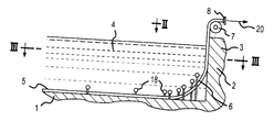
- FIG. 1 is a partial cross-sectional view through a water reservoir that is to be aerated showing one exemplary embodiment of the inventive apparatus;
- FIG. 2 is a partial plan view of the reservoir portion of FIG. 1 taken in the direction of the arrow 11 ;
- FIG. 3 is a cross-sectional view taken in the direction of the line III—III in FIG. 1;
- FIG. 4 is a partial cross-sectional view taken along the line IV—IV in FIG. 2 .
- the aerating apparatus of the present invention is characterized primarily in that the aerating element, which is inextensible, is longitudinally displaceably held by preferably a plurality of holding means in such a way that a pulling action on one end of the aerating element allows the entire aerating element to be pulled out of its holding means and, for example, to be replaced by a following, further aerating element.
- the pulling action which is applied, for example, by a winch and by winding up the old aerating element, can, however, also be advantageous for both ends of the aerating element in order in this way to be able to keep the aerating element taut during the aerating operation.
- the holding means are advantageously holding elements that entirely or partially span or overlap the aerating elements, yet on those sides that face the aerating elements must be embodied in such a way that the desired relative movements are possible.
- smooth, expediently convex guide surfaces or even cylindrical members can be provided that are also mounted so as to be rotatable.
- the holding means that span the aerating elements must also be embodied in such a way that (when the aerating elements are not subjected to an internal pressure) an adequate clearance exists between the holding means and the aerating elements so that during longitudinal displacement of the aerating elements binding of the aerating elements and excessive frictional resistance are precluded.
- aerating elements 5 disposed within a water tank or reservoir, which has a base 1 , side walls 2 , an outer edge 3 , and a water fill 4 .
- the aerating elements 5 which extend over the greatest portion of the width of the reservoir, rest upon the base 1 and at both sides of the reservoir extend vertically upwardly after passing through a curved section 6 .
- the aerating elements 5 are guided outwardly and to the side over a roller 7 , which could be driveable.
- the aerating elements are here provided with a coupling 8 to which a compressed air line could be connected. Only one edge of the water reservoir is illustrated in FIG. 1 .
- the opposite edge could have the same or similar configuration, or it would also be possible to eliminate the curved section 6 and/or the vertically upwardly directed portion.
- the strip-like aerating elements 5 comprise a lower strip 9 , an upper strip 10 , and edge members 11 by means of which the parts 9 , 10 merge with one another as a single piece.
- the components 9 , 10 and 11 are made of rubber or some other elastomeric material.
- the edge members 11 have embedded therein inextensible cables 12 . It would also be possible to achieve the tensile strength and possibly also transverse rigidity via other reinforcing inserts, such as fabric inserts in the lower strip 9 .
- the important thing is that the upper strip 10 is provided with continuous slits that permit the desired aeration of the water fill with fine bubbles.
- the compressed air is introduced into the space 13 between the two strips 9 , 10 , with the space 13 serving as an air supply channel.
- the air widens the slits so that the fine air bubbles can be discharged.
- the upper strip 10 is provided with slits only in that longitudinal portion of the aerating elements 5 that are directly proximate to the base 1 . In the end portions, the aerating elements 5 thus serve only for the supply of air to the longitudinal sections that are provided with slits.
- a critical feature is the mounting means for the aerating elements 5 in order to ensure their position in the various longitudinal sections of FIGS. 1 to 3 .
- hollow or U rails 14 which serve to engage the heads of vertically upright bolts 15 on which are threaded in a height adjustable manner, nuts 17 that at the top are provided with an eye 16 .
- These eyes serve for holding horizontal pipes 18 against the bottom of which rest the aerating elements 5 when they expand with internal pressure.
- the pipes 18 can also be mounted so as to be rotatable. In any case, the pipes 18 must be disposed with clearance above the aerating elements 5 , which clearance is readily reduced or eliminated when the aerating elements 5 expand.
- the aerating elements 5 are disposed in pairs, the pipes 18 of adjacent aerating elements 5 are offset relative to one another.
- the holding means in the vicinity of the curved sections 6 are installed at varying heights (see, for example, FIG. 1 ). Furthermore, the spacing of the holding means from one another is such that the aerating elements 5 can bulge upwardly only slightly between successive mounting means.
- the pulling effect in the direction of the arrow 20 furthermore has the advantage that the aerating elements 5 can also be kept under tension during aeration.
- each of the aerating elements 5 can be withdrawn from the water reservoir without for this purpose having to empty the water reservoir to thereby preclude undesired bulging between the mounting means.
- another aerating element can be installed by connecting the front end thereof with the back end of the aerating element 5 that is to be removed.
- the aerating element 5 that is to be removed serves as an auxiliary aid for drawing in or inserting a new element.
- the aerating elements 5 are embodied merely as pulling members with which, however, compressed air feed lines are preferably associated in order to ensure the supply of compressed air.
- the pulling members can, for example, be embodied as bands or cables.
Landscapes
- Chemical & Material Sciences (AREA)
- Chemical Kinetics & Catalysis (AREA)
- Life Sciences & Earth Sciences (AREA)
- Hydrology & Water Resources (AREA)
- Engineering & Computer Science (AREA)
- Environmental & Geological Engineering (AREA)
- Water Supply & Treatment (AREA)
- Organic Chemistry (AREA)
- Biodiversity & Conservation Biology (AREA)
- Microbiology (AREA)
- Aeration Devices For Treatment Of Activated Polluted Sludge (AREA)
Abstract
An apparatus for aerating water with fine bubbles is provided. At least one strip-like, inextensible aerating element is provided that has an air supply channel and there above a portion that is provided with slits which elastically widen under the effect of a supply of air. At least one holding element is secured to the base of a water reservoir that is to be aerated, wherein the aerating element is longitudinally displaceably held by the holding element such that with the reservoir filled, a pulling action on one end of the aerating element results in withdrawal thereof from the holding element.
Description
The present invention relates to an apparatus for aerating water with fine bubbles, and includes at least one strip-like aerating element having an air supply channel and there above a wall that is provided with slits that elastically widen under the effect of supply of air, whereby the aerating element is secured against undesired lifting movements by means of holding means secured to the base of the water reservoir that is to be aerated.
With heretofore known apparatus of this type, the aerating elements are originally secured in the base region of the water reservoir. For this purpose, special anchoring means or fixedly installed tubular lines are provided via which the compressed air is supplied to the aerating elements. It is to be understood that if the aerating element becomes worn or damaged, special precautions must be taken in order to be able to replace the aerating element since repair is normally not possible on location. Rather, it is always necessary to first empty the water reservoir in order to even be able to disassemble the apparatus.
It is therefore an object of the present invention to be able to preclude the aforementioned drawbacks in a practical manner. In particular, disassembly and assembly should be capable of being carried out without having to lower the water level.
This object, and other objects and advantages of the present invention, will appear more clearly from the following specification in conjunction with the accompanying schematic drawing, in which:
FIG. 1 is a partial cross-sectional view through a water reservoir that is to be aerated showing one exemplary embodiment of the inventive apparatus;
FIG. 2 is a partial plan view of the reservoir portion of FIG. 1 taken in the direction of the arrow 11;
FIG. 3 is a cross-sectional view taken in the direction of the line III—III in FIG. 1; and
FIG. 4 is a partial cross-sectional view taken along the line IV—IV in FIG. 2.
The aerating apparatus of the present invention is characterized primarily in that the aerating element, which is inextensible, is longitudinally displaceably held by preferably a plurality of holding means in such a way that a pulling action on one end of the aerating element allows the entire aerating element to be pulled out of its holding means and, for example, to be replaced by a following, further aerating element. The pulling action, which is applied, for example, by a winch and by winding up the old aerating element, can, however, also be advantageous for both ends of the aerating element in order in this way to be able to keep the aerating element taut during the aerating operation. Furthermore, it is, however, also possible to equip the ends of the aerating element with inextensible cables or bands as extensions by means of which the aerating element can be pulled into or withdrawn from the operative position.
The holding means are advantageously holding elements that entirely or partially span or overlap the aerating elements, yet on those sides that face the aerating elements must be embodied in such a way that the desired relative movements are possible. For example, smooth, expediently convex guide surfaces or even cylindrical members can be provided that are also mounted so as to be rotatable. Furthermore, the holding means that span the aerating elements must also be embodied in such a way that (when the aerating elements are not subjected to an internal pressure) an adequate clearance exists between the holding means and the aerating elements so that during longitudinal displacement of the aerating elements binding of the aerating elements and excessive frictional resistance are precluded.
Further specific features of the present invention will be provided in detail subsequently.
Referring now to the drawing in detail, disposed within a water tank or reservoir, which has a base 1, side walls 2, an outer edge 3, and a water fill 4, are a plurality of aerating elements 5 that are combined in pairs and extend parallel to one another. The aerating elements 5, which extend over the greatest portion of the width of the reservoir, rest upon the base 1 and at both sides of the reservoir extend vertically upwardly after passing through a curved section 6. At the outer edge 3, the aerating elements 5 are guided outwardly and to the side over a roller 7, which could be driveable. The aerating elements are here provided with a coupling 8 to which a compressed air line could be connected. Only one edge of the water reservoir is illustrated in FIG.1. The opposite edge could have the same or similar configuration, or it would also be possible to eliminate the curved section 6 and/or the vertically upwardly directed portion.
The strip-like aerating elements 5 comprise a lower strip 9, an upper strip 10, and edge members 11 by means of which the parts 9, 10 merge with one another as a single piece. The components 9, 10 and 11 are made of rubber or some other elastomeric material. In order to make the aerating elements 5 tension proof, the edge members 11 have embedded therein inextensible cables 12. It would also be possible to achieve the tensile strength and possibly also transverse rigidity via other reinforcing inserts, such as fabric inserts in the lower strip 9. The important thing is that the upper strip 10 is provided with continuous slits that permit the desired aeration of the water fill with fine bubbles. In this connection, the compressed air is introduced into the space 13 between the two strips 9, 10, with the space 13 serving as an air supply channel. The air widens the slits so that the fine air bubbles can be discharged. It is to be understood that the upper strip 10 is provided with slits only in that longitudinal portion of the aerating elements 5 that are directly proximate to the base 1. In the end portions, the aerating elements 5 thus serve only for the supply of air to the longitudinal sections that are provided with slits.
A critical feature is the mounting means for the aerating elements 5 in order to ensure their position in the various longitudinal sections of FIGS. 1 to 3. For this purpose, secured to the base 1 are hollow or U rails 14, which serve to engage the heads of vertically upright bolts 15 on which are threaded in a height adjustable manner, nuts 17 that at the top are provided with an eye 16. These eyes serve for holding horizontal pipes 18 against the bottom of which rest the aerating elements 5 when they expand with internal pressure. The pipes 18 can also be mounted so as to be rotatable. In any case, the pipes 18 must be disposed with clearance above the aerating elements 5, which clearance is readily reduced or eliminated when the aerating elements 5 expand.
Since the aerating elements 5 are disposed in pairs, the pipes 18 of adjacent aerating elements 5 are offset relative to one another. In addition, the holding means in the vicinity of the curved sections 6 are installed at varying heights (see, for example, FIG. 1). Furthermore, the spacing of the holding means from one another is such that the aerating elements 5 can bulge upwardly only slightly between successive mounting means.
The pulling effect in the direction of the arrow 20 furthermore has the advantage that the aerating elements 5 can also be kept under tension during aeration.
The inventive mounting of the inextensible aerating elements 5 enables a longitudinal displacement thereof. By means of a pulling effect in the direction of the arrow 20, each of the aerating elements 5 can be withdrawn from the water reservoir without for this purpose having to empty the water reservoir to thereby preclude undesired bulging between the mounting means. Along with the withdrawal of an aerating element 5, another aerating element can be installed by connecting the front end thereof with the back end of the aerating element 5 that is to be removed. In this connection, the aerating element 5 that is to be removed serves as an auxiliary aid for drawing in or inserting a new element.
In the region of the curved sections 6 to the connections or couplings 8, the aerating elements 5 are embodied merely as pulling members with which, however, compressed air feed lines are preferably associated in order to ensure the supply of compressed air. The pulling members can, for example, be embodied as bands or cables.
It is often advantageous to associate an air supply connection to both ends of an aerating element 5 in order to improve the uniformity of the aeration over the length of the element.
The present invention is, of course, in no way restricted to the specific disclosure of the specification and drawings, but also encompasses any modifications within the scope of the appended claims.
Claims (16)
1. An apparatus for aerating water with fine bubbles comprising:
at least one strip-type, inextensible aerating element having an air supply channel and there above a portion that is provided with slits which elastically widen under the effect of a supply of air; and
at least one holding means secured to a base of a water reservoir that is to be aerated, wherein said at least one aerating element is longitudinally diplaceably held by said holding means such that with said water reservoir filled, a pulling action on one end of said at least one aerating element allows withdrawal of said aerating element from said holding means, and wherein said at least one aerating element, at an end thereof opposite said one end, is provided with fastening means for pulling another one of said at least one aerating element after said aerating element that is being withdrawn.
2. An apparatus according to claim 1 , which includes a plurality of holding means.
3. An apparatus according to claim 1 , wherein opposite ends of said at least one aerating element are provided with at least one of a compressed air connection and means suitable for transferring pulling action.
4. An apparatus according to claim 1 , wherein at least said one end of said at least one aerating element is guided out of said water reservoir and in a region of a reservoir edge is associated with a deflection means.
5. An apparatus according to claim 4 , wherein said deflection means is in the form of a roller onto which said at least one aerating element is wound or by means of which said aerating element is guided.
6. An apparatus according to claim 1 , which includes a plurality of said aerating elements disposed in pairs and parallel to one another.
7. An apparatus according to claim 1 , wherein said at least one holding means comprises components that at least partially span said at least one aerating element and are disposed with clearance over said at least one aerating element when the latter is not pressurized.
8. An apparatus according to claim 7 , wherein sides of said components that face said at least one aerating element are rounded or convex.
9. An apparatus according to claim 8 , wherein said components are part of a rotatable roller.
10. An apparatus according to claim 7 , wherein said components are adjustable in height.
11. An apparatus according to claim 1 , wherein only portions of at least one aerating element that are disposed horizontally on said base of said water reservoir are provided with slitted portions that are suitable for the discharge of air bubbles.
12. An apparatus according to claim 1 , wherein said at least one aerating element, when in a state of rest and hence not pressurized, has an essentially flat rectangular configuration, an d is comprised of an elastomer, and wherein said at least one aerating element is proyided with reinforcing inserts to make it inextensible.
13. An apparatus according to claim 1 , wherein a plurality of parallel aerating elements are provided, and wherein each of said aerating elements is provided with its own compressed air connection that is provided with a shutoff device.
14. An apparatus according to claim 5 , wherein said roller is driveable.
15. An apparatus according to claim 12 , wherein said reinforcing inserts also make said at least one aerating element transversely rigid.
16. An apparatus for aerating water with fine bubbles comprising:
at least one strip-type, inextensible aerating element having an air supply channel and there above a portion that is provided with slits which elastically widen under the effect of a supply of air; and
at least one holding means secured to a base of a water reservoir that is to be aerated, wherein said at least one aerating element is longitudinally diplaceably held by said holding means such that with said water reservoir filled, a pulling action on one end of said at least one aerating element allows withdrawal of said aerating element from said holding means, wherein said at least one holding means comprises components that at least partially span said at least one aerating element and are disposed with clearance over said at least one aerating element when the latter is not pressurized, and wherein said components are adjustable in height.
Priority Applications (3)
| Application Number | Priority Date | Filing Date | Title |
|---|---|---|---|
| DE1999108912 DE19908912A1 (en) | 1999-03-02 | 1999-03-02 | Water aerator made of elastic material that can be withdrawn through its retainers to allow replacement in full tank |
| EP20000106997 EP1138371A1 (en) | 1999-03-02 | 2000-04-01 | Device for water aeration |
| US09/550,445 US6367784B1 (en) | 1999-03-02 | 2000-04-17 | Apparatus for aerating water |
Applications Claiming Priority (3)
| Application Number | Priority Date | Filing Date | Title |
|---|---|---|---|
| DE1999108912 DE19908912A1 (en) | 1999-03-02 | 1999-03-02 | Water aerator made of elastic material that can be withdrawn through its retainers to allow replacement in full tank |
| EP20000106997 EP1138371A1 (en) | 1999-03-02 | 2000-04-01 | Device for water aeration |
| US09/550,445 US6367784B1 (en) | 1999-03-02 | 2000-04-17 | Apparatus for aerating water |
Publications (1)
| Publication Number | Publication Date |
|---|---|
| US6367784B1 true US6367784B1 (en) | 2002-04-09 |
Family
ID=27219004
Family Applications (1)
| Application Number | Title | Priority Date | Filing Date |
|---|---|---|---|
| US09/550,445 Expired - Fee Related US6367784B1 (en) | 1999-03-02 | 2000-04-17 | Apparatus for aerating water |
Country Status (3)
| Country | Link |
|---|---|
| US (1) | US6367784B1 (en) |
| EP (1) | EP1138371A1 (en) |
| DE (1) | DE19908912A1 (en) |
Cited By (2)
| Publication number | Priority date | Publication date | Assignee | Title |
|---|---|---|---|---|
| US20070257382A1 (en) * | 2006-05-08 | 2007-11-08 | Tekni-Plex, Inc. | Aeration device for use as a diffuser |
| US10105659B2 (en) * | 2013-03-15 | 2018-10-23 | Claudius Jaeger | Dual control lateral air manifold assembly |
Citations (11)
| Publication number | Priority date | Publication date | Assignee | Title |
|---|---|---|---|---|
| US1703967A (en) * | 1926-05-07 | 1929-03-05 | Koppers Co Inc | Aeration apparatus and method |
| US1717713A (en) * | 1926-06-28 | 1929-06-18 | Koppers Co Inc | Aeration apparatus |
| US3432154A (en) * | 1967-11-29 | 1969-03-11 | Martin Hermann Danjes | Sewage water aeration device |
| US3880965A (en) * | 1972-11-24 | 1975-04-29 | Charles G Dudis | Apparatus for aerating a liquid |
| US4029581A (en) * | 1974-12-26 | 1977-06-14 | Xodar Corporation | Aerating system |
| US4051035A (en) * | 1976-08-16 | 1977-09-27 | Ralph B. Carter Company | Apparatus for the aerobic treatment of liquid waste |
| US4488508A (en) * | 1983-06-10 | 1984-12-18 | Heideman Robert C | Aeration/circulation method and apparatus utilizing low pressure air |
| US5160460A (en) * | 1989-01-31 | 1992-11-03 | Metz Mannheim Gmbh | Ventilation system for a liquid-filled basin |
| US5290487A (en) * | 1991-08-30 | 1994-03-01 | Scheibinger Ludwig | Device for aeration of a liquid vessel |
| US5690864A (en) * | 1996-06-17 | 1997-11-25 | Tyer; Robert R. | Retrievable aeration system |
| US5851447A (en) * | 1996-06-17 | 1998-12-22 | Aer Research, Inc. | Floor-mounted aeration system |
Family Cites Families (2)
| Publication number | Priority date | Publication date | Assignee | Title |
|---|---|---|---|---|
| DE19540945A1 (en) * | 1995-11-03 | 1997-05-07 | Oms Klaeranlagen Gmbh | Surface aerator for settlement tanks comprising horizontal composite of hollow sections |
| US5804104A (en) * | 1997-03-13 | 1998-09-08 | Meurer Industries, Inc. | Apparatus for moving an aeration unit |
-
1999
- 1999-03-02 DE DE1999108912 patent/DE19908912A1/en not_active Withdrawn
-
2000
- 2000-04-01 EP EP20000106997 patent/EP1138371A1/en not_active Withdrawn
- 2000-04-17 US US09/550,445 patent/US6367784B1/en not_active Expired - Fee Related
Patent Citations (11)
| Publication number | Priority date | Publication date | Assignee | Title |
|---|---|---|---|---|
| US1703967A (en) * | 1926-05-07 | 1929-03-05 | Koppers Co Inc | Aeration apparatus and method |
| US1717713A (en) * | 1926-06-28 | 1929-06-18 | Koppers Co Inc | Aeration apparatus |
| US3432154A (en) * | 1967-11-29 | 1969-03-11 | Martin Hermann Danjes | Sewage water aeration device |
| US3880965A (en) * | 1972-11-24 | 1975-04-29 | Charles G Dudis | Apparatus for aerating a liquid |
| US4029581A (en) * | 1974-12-26 | 1977-06-14 | Xodar Corporation | Aerating system |
| US4051035A (en) * | 1976-08-16 | 1977-09-27 | Ralph B. Carter Company | Apparatus for the aerobic treatment of liquid waste |
| US4488508A (en) * | 1983-06-10 | 1984-12-18 | Heideman Robert C | Aeration/circulation method and apparatus utilizing low pressure air |
| US5160460A (en) * | 1989-01-31 | 1992-11-03 | Metz Mannheim Gmbh | Ventilation system for a liquid-filled basin |
| US5290487A (en) * | 1991-08-30 | 1994-03-01 | Scheibinger Ludwig | Device for aeration of a liquid vessel |
| US5690864A (en) * | 1996-06-17 | 1997-11-25 | Tyer; Robert R. | Retrievable aeration system |
| US5851447A (en) * | 1996-06-17 | 1998-12-22 | Aer Research, Inc. | Floor-mounted aeration system |
Cited By (4)
| Publication number | Priority date | Publication date | Assignee | Title |
|---|---|---|---|---|
| US20070257382A1 (en) * | 2006-05-08 | 2007-11-08 | Tekni-Plex, Inc. | Aeration device for use as a diffuser |
| WO2007133490A1 (en) | 2006-05-08 | 2007-11-22 | Tekni-Plex, Inc. | Aeration device for use as a diffuser |
| US7934706B2 (en) | 2006-05-08 | 2011-05-03 | Tekni-Plex, Inc. | Aeration device for use as a diffuser |
| US10105659B2 (en) * | 2013-03-15 | 2018-10-23 | Claudius Jaeger | Dual control lateral air manifold assembly |
Also Published As
| Publication number | Publication date |
|---|---|
| EP1138371A1 (en) | 2001-10-04 |
| DE19908912A1 (en) | 2000-09-07 |
Similar Documents
| Publication | Publication Date | Title |
|---|---|---|
| US6382385B2 (en) | Roller conveying apparatus | |
| US4846352A (en) | Screen clamp | |
| EP1523421B1 (en) | Device for increasing the road safety of covered vehicles | |
| US9370752B2 (en) | Aeration element for the gasification of liquids | |
| KR102401027B1 (en) | Assembly bracket and mounting system for aeration element | |
| US6367784B1 (en) | Apparatus for aerating water | |
| HU213663B (en) | Apparatus for aeration of bassins filled with fluid | |
| JPH01500497A (en) | Method and apparatus for performing fine bubble aeration over a large area of liquid | |
| US5160460A (en) | Ventilation system for a liquid-filled basin | |
| DE2238953A1 (en) | PROCEDURES AND DEVICE FOR ASSEMBLY AND REPAIR OF VESSELS OR THE LIKE | |
| CA2306268A1 (en) | Apparatus for aerating water | |
| US9561480B2 (en) | Assembly bracket and mounting system for aeration element | |
| US9151073B2 (en) | Underground tank hold-down system | |
| US20070205599A1 (en) | Brake hose lifting apparatus | |
| US9045205B2 (en) | Floatable boat ramp | |
| KR100870490B1 (en) | Water and sewage pipe repair and reinforcement device | |
| DE2062535A1 (en) | Device for the joint removal and placement of a plurality of cops or sleeves placed on spindles on ring spinning and ring twisting machines | |
| EP0218315A2 (en) | Improved screen clamp | |
| GB2162131A (en) | Improvements in or relating to buoyancy tubes | |
| DE29917373U1 (en) | Freight wagons with load securing, especially for jumbo gravure rolls | |
| CN224032207U (en) | A device for tying longitudinal distribution bars in the web of a railway box girder reinforcement cage | |
| WO1993017798A1 (en) | Mounting and tensioning arrangements for screens | |
| KR102357372B1 (en) | Buffer float binding device and structure of buffer using the same | |
| EP0159761A2 (en) | Fastening device for fascine mattresses | |
| KR20200133060A (en) | Bulk Tank Discharge System |
Legal Events
| Date | Code | Title | Description |
|---|---|---|---|
| AS | Assignment |
Owner name: GUMMI-JAGER KG GMBH & CIE, GERMANY Free format text: ASSIGNMENT OF ASSIGNORS INTEREST;ASSIGNOR:JAGER, ANREAS;REEL/FRAME:010732/0931 Effective date: 20000403 |
|
| REMI | Maintenance fee reminder mailed | ||
| LAPS | Lapse for failure to pay maintenance fees | ||
| STCH | Information on status: patent discontinuation |
Free format text: PATENT EXPIRED DUE TO NONPAYMENT OF MAINTENANCE FEES UNDER 37 CFR 1.362 |
|
| FP | Lapsed due to failure to pay maintenance fee |
Effective date: 20060409 |