US6357093B1 - Shoelace fastener - Google Patents
Shoelace fastener Download PDFInfo
- Publication number
- US6357093B1 US6357093B1 US09/592,330 US59233000A US6357093B1 US 6357093 B1 US6357093 B1 US 6357093B1 US 59233000 A US59233000 A US 59233000A US 6357093 B1 US6357093 B1 US 6357093B1
- Authority
- US
- United States
- Prior art keywords
- shoelace
- fastener
- shank
- serrate
- holder piece
- Prior art date
- Legal status (The legal status is an assumption and is not a legal conclusion. Google has not performed a legal analysis and makes no representation as to the accuracy of the status listed.)
- Expired - Fee Related
Links
Images


Classifications
-
- A—HUMAN NECESSITIES
- A43—FOOTWEAR
- A43C—FASTENINGS OR ATTACHMENTS OF FOOTWEAR; LACES IN GENERAL
- A43C3/00—Hooks for laces; Guards for hooks
-
- Y—GENERAL TAGGING OF NEW TECHNOLOGICAL DEVELOPMENTS; GENERAL TAGGING OF CROSS-SECTIONAL TECHNOLOGIES SPANNING OVER SEVERAL SECTIONS OF THE IPC; TECHNICAL SUBJECTS COVERED BY FORMER USPC CROSS-REFERENCE ART COLLECTIONS [XRACs] AND DIGESTS
- Y10—TECHNICAL SUBJECTS COVERED BY FORMER USPC
- Y10T—TECHNICAL SUBJECTS COVERED BY FORMER US CLASSIFICATION
- Y10T24/00—Buckles, buttons, clasps, etc.
- Y10T24/37—Drawstring, laced-fastener, or separate essential cooperating device therefor
- Y10T24/3703—Includes separate device for holding drawn portion of lacing
- Y10T24/3713—Includes separate device for holding drawn portion of lacing having relatively movable holding components or surfaces
- Y10T24/3718—Includes separate device for holding drawn portion of lacing having relatively movable holding components or surfaces with integral resilient linking structure therebetween
- Y10T24/3721—Includes separate device for holding drawn portion of lacing having relatively movable holding components or surfaces with integral resilient linking structure therebetween formed from wire
Definitions
- the present invention relates to a shoelace fastener, and more particularly relates to a fastening device for preventing loosening of a shoelace suited for use on athletic shoes.
- the size of a shoe is usually designed a little larger than the standard real foot size in the region of the sole in order to provide good fit whilst allowing slight deformation of the foot during use. Such deformation of the foot usually appears in the intermediate section between the transverse arch and the ball of the foot.
- a shoelace fastener comprises a holder piece, a fastener cap to be combined with the holder piece and a washer to be interposed between the holder piece and the fastener cap.
- the holder piece is made up of a serrate shank to be inserted through an eyelet of a shoe and an integral flat head adapted for contact with the inner surface of a flap of the shoe.
- the fastener cap is adapted for engagement with the serrate shank of the holder piece on the outer surface of the flap.
- the washer is provided with holes for passage of a shoelace and the serrate shank.
- FIG. 1 is a sectional side plan view of the basic embodiment of the shoelace fastener in accordance with the present invention
- FIG. 2 is a sectional side view of a modified embodiment of the shoelace fastener
- FIG. 3 is top plan views of various embodiments of the washer used for the shoelace fastener
- FIG. 4 is top plan views of various embodiments of the clamp piece used for the shoelace fastener
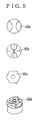
- FIG. 5 is top plan views of various embodiments of the holder piece used for the shoelace fastener
- FIGS. 6A and 6B are sectional side plan views of different modes of assemblage of the shoelace fastener
- FIGS. 7A and 7B are sectional side plan views of different modes of shoelace clamping
- FIG. 8 is a sectional side plan view of a further modified embodiment of the shoelace fastener
- FIGS. 9A and 9B are sectional top plan and perspective plan view of the fastener shown in FIG. 8,
- FIGS. 10A and 10B are perspective plan views of different modes of fastener attachment.
- FIG. 11 is a sectional side plan view of a further embodiment of the shoelace fastener in accordance with the present invention.
- FIG. 1 The basic embodiment of the shoelace fastener in accordance with the present invention is shown in FIG. 1, in which the shoelace holder includes a holder piece 40 , a fastener cap 10 and a washer 20 .
- the serration on the shank is given in the form of a thread and the fastener cap is put into screw engagement with the serrate shank of the holder piece.
- the holder piece 40 includes a thread shank 41 and a flat head 42 formed integrally with the thread shank 41 .
- the thread shank 41 is adapted for insertion through an eyelet in the flap of a shoe for which the shoelace fastener is used.
- the flat head 42 is adapted for contact with the inner surface of the flap of the shoe.
- the fastener cap 10 is provided with an axially through, threaded hole 11 adapted for screw engagement with the thread shank 41 of the holder piece 40 .
- the washer 20 is given substantially in the form of a flat disc and provided with the first through hole 21 for passage of a shoelace 50 and the second through hole for free passage of the thread shank 41 of the holder piece 40 .
- the first through hole 21 is formed at a position to be covered by the bottom surface of the holder piece 40 when combined for use.
- the thread shank 41 of the holder piece 40 is first inserted from downside through an eyelet in the flap of a shoe and the washer 20 is inserted over the thread shank 41 .
- a shoelace 50 is inserted through the first through hoe 21 in the washer 20 and turned back.
- the fastener cap 10 is inserted over the thread shank 41 and turned tightly for screw engagement, thereby clamping the shoelace 50 between the bottom surface of the fastener cap 10 and the top surface of the washer 20 as well as between the bottom surface of the washer 20 and the top surface of the flap 60 as illustrated.
- Such double clamping reliably prevents accidental loosening of the shoelace 50 even during intense athletic movements.
- FIG. 2 A modified embodiment of the shoelace fastener in accordance with the present invention is shown in FIG. 2, in which the shoelace holder includes a holder piece 40 , a fastener cap 10 , a washer 20 and a clamp piece 30 .
- the constructions of the holder piece 40 , the fastener cap 10 and the washer 20 are same as those shown in FIG. 1 .
- the clamp piece 30 is given substantially in the form of a flat disc and provided with a through hole 31 for free passage of the thread shank 41 of the holder piece 40 .
- the first through hole 21 for passage of the shoelace 50 is formed at a position not covered by the fastener cap 10 when used.
- the shoelace 50 is clamped between the bottom surface of the washer 20 and the top surface of the clamp piece 30 .
- the shoelace fastener in accordance with the present invention is made of metal, synthetic resin or synthetic rubber.
- an elastic tube is preferably fitted into the through hole 21 in the washer 20 and the through hole 31 in the clamp piece 30 in order to protect the thread shank 41 against accidental impactive contact with the washer 20 and the clamp piece 30 .
- the contour of the through holes 21 and 31 can be designed freely in accordance with the cross sectional profile of the shoelace for which the shoelace fastener is used.
- FIG. 3 Some examples of the washer 20 are shown in FIG. 3, whereas some examples of the clamp piece 30 are shown in FIG. 4 .
- the washers and the clamp pieces of the same alphabetic suffix are used in combination.
- the dashed/dotted lines in the illustration indicates the contour of the fastener cap 10 in the combined position.
- the first through hole 21 for the shoelace 50 is covered by the fastener cap 10 .
- the through hole 21 is partly covered by the fastener cap 10 .
- the hole 21 is not covered by the fastener cap 10 .
- the clamp piece 30 is preferably provided with a pair of opposed side bulges 32 which stably embrace the washer 20 when combined.
- FIGS. 6A and 6B Different modes of assemblage are shown in FIGS. 6A and 6B.
- the clamp piece 30 In the mode shown in FIG. 6A, the clamp piece 30 is located on the washer 20 and, consequently, the side bulges 32 project downwards. Whereas, in the mode shown in FIG. 6B, the clamp piece 30 is located below the washer 20 and, consequently, the side bulges 32 project upwards. Either assemblage may be employed depending on the condition of real use.
- FIGS. 7A and 7B Different modes of passage of the shoelace 50 are shown in FIGS. 7A and 7B. In either case, the shoelace 50 is clamped outside the contour of the fastener cap 10 . In the mode shown in FIG. 7A, only the washer 20 is provided with the through hole 21 for the shoelace 50 . Whereas, in the mode shown in FIG. 7B, only the clamp piece 30 is provided with the through hole 31 for the shoelace 50 . Either mode may be employed depending on the condition of real use.
- FIGS. 8, 9 A and 9 B A further embodiment of the shoelace fastener in accordance with the present invention is shown in FIGS. 8, 9 A and 9 B, in which the serration on the shank is given in the form of one or more annular grooves and the fastener cap is put into hook engagement with the serrate shank of the holder piece.
- fastener cap 110 includes a cylindrical main body 111 closed at both ends and provided with a circumferential slot 112 formed in its side wall.
- a bent leaf spring 113 is fixed to the inner side wall of the main body 111 .
- a through hole is formed at the center of the bottom for free passage of the serrate shank.
- a holder piece 140 is made up of a serrate shank 141 and a flat head 142 formed in one body with the serrate shank 141 .
- the serrate shank 141 is provided with one or more annular grooves.
- An elongate hook 114 is provided with an outer knob 115 adapted for manual operation and an inner tip in contact with the leaf spring 113 .
- a joint extends slidably through the slot 112 in the main body 111 whilst connecting the knob 115 to the inner tip.
- the knob 115 is located outside the main body 111 due to spring repulsion when no manual operation is applied to the hook 114 .
- the hook 114 is further provided with a through hole 116 for free passage of the serrate shank 141 of the holder piece 140 . In the position shown in FIG. 9A, i.e. no manual operation is applied to the knob 115 , the center of the through hole 116 in the hook 114 is biased outwards from the center of the through hole in the bottom of the main body 111 .
- a pair of opposite guide bulges 117 are preferably formed on the inner side wall of the main body 111 of the fastener cap 110 .
- the washer 20 is placed in position on the flap 60 and the holder piece 140 is inserted into the through hole via the eyelet in the flap 60 .
- the knob 115 of the hook 114 is pushed inwards so that the center of the through hole 116 in the hook 114 meets the center of the through hole in the bottom of the main body 111 and the fastener cap 110 is inserted over the serrate shank 141 of the holder piece 140 .
- the manual operation on the knob 115 is removed so that the hook 114 moves outwards due to the spring repulsion.
- circumferential edge of the through hole in the hook 114 engages with one of the annular grooves on the serrate shank 141 .
- the shoelace 50 is clamped between the bottom surface of the fastener cap 110 and the top surface of the washer 20 as well as between the bottom surface of the washer 20 and the flap 60 .
- the shoelace fastener in accordance with the present invention may be attached either to all the eyelets in the flap as shown in FIG. 10A or to some selected ones as shown in FIG. 10 B.
- the holder piece 40 may be fixed to the flap 60 of the shoe by set bolts 70 .
Landscapes
- Footwear And Its Accessory, Manufacturing Method And Apparatuses (AREA)
Abstract
A fastener for preventing undesirable, accidental loosening of a shoelace during use. The fastener includes a holder piece made up of a serrate shank to be inserted through an eyelet of a shoe and an integral flat head adapted for pressure contact with the inner surface of a flap of the shoe. A fastener cap is put into engagement with the serrate shank on the outer surface of the flap for fastening purposes. A washer is interposed between the flap and the fastener cap and provided with the first through hole free passage of the shoelace and the second through hole for free passage of the serrate shank.
Description
The present invention relates to a shoelace fastener, and more particularly relates to a fastening device for preventing loosening of a shoelace suited for use on athletic shoes.
The size of a shoe is usually designed a little larger than the standard real foot size in the region of the sole in order to provide good fit whilst allowing slight deformation of the foot during use. Such deformation of the foot usually appears in the intermediate section between the transverse arch and the ball of the foot.
Before using a shoe, its shoelace is knotted tightly on the flap by a user so as to fix the shoe onto the foot. Due to repeated deformation of the foot during use, however, the shoelace loosens gradually on the flat of the shoe. As the shoelace loosens, the foot is biased forwards within the shoe and the user's fingers are pressed against the inside of the toe box. This forced contact pains considerably the foot of the user. In addition, the forward bias of the foot within the shoe develops a gap between the heel of the user and the counter of the shoe. This gap allows frequent up and down movement of the foot during use and causes repeated frictional contact of the heel and the inside of the counter. This repeated frictional contact also pains the foot of the user.
In addition to such pain, loosening of the shoelace allows relatively free movement of the foot within the shoe and the user loses reliable control on the shoe.
The pains on the foot and the poor control on the shoe concur to form fatal drawbacks in particular when the shoe is used for athletic purposes or long travels.
It is thus the prime object of the present invention to prevent loosening of a shoelace during use, thereby removing uncomfortable pain on a user's foot and assuring reliable control on a shoe even during intense athletic movements.
In accordance with the basic concept of the present invention, a shoelace fastener comprises a holder piece, a fastener cap to be combined with the holder piece and a washer to be interposed between the holder piece and the fastener cap. The holder piece is made up of a serrate shank to be inserted through an eyelet of a shoe and an integral flat head adapted for contact with the inner surface of a flap of the shoe. The fastener cap is adapted for engagement with the serrate shank of the holder piece on the outer surface of the flap. The washer is provided with holes for passage of a shoelace and the serrate shank.
FIG. 1 is a sectional side plan view of the basic embodiment of the shoelace fastener in accordance with the present invention,
FIG. 2 is a sectional side view of a modified embodiment of the shoelace fastener,
FIG. 3 is top plan views of various embodiments of the washer used for the shoelace fastener,
FIG. 4 is top plan views of various embodiments of the clamp piece used for the shoelace fastener,
FIG. 5 is top plan views of various embodiments of the holder piece used for the shoelace fastener,
FIGS. 6A and 6B are sectional side plan views of different modes of assemblage of the shoelace fastener,
FIGS. 7A and 7B are sectional side plan views of different modes of shoelace clamping,
FIG. 8 is a sectional side plan view of a further modified embodiment of the shoelace fastener,
FIGS. 9A and 9B are sectional top plan and perspective plan view of the fastener shown in FIG. 8,
FIGS. 10A and 10B are perspective plan views of different modes of fastener attachment, and
FIG. 11 is a sectional side plan view of a further embodiment of the shoelace fastener in accordance with the present invention.
The basic embodiment of the shoelace fastener in accordance with the present invention is shown in FIG. 1, in which the shoelace holder includes a holder piece 40, a fastener cap 10 and a washer 20. The serration on the shank is given in the form of a thread and the fastener cap is put into screw engagement with the serrate shank of the holder piece.
More specifically, the holder piece 40 includes a thread shank 41 and a flat head 42 formed integrally with the thread shank 41. The thread shank 41 is adapted for insertion through an eyelet in the flap of a shoe for which the shoelace fastener is used. Whereas, the flat head 42 is adapted for contact with the inner surface of the flap of the shoe.
The fastener cap 10 is provided with an axially through, threaded hole 11 adapted for screw engagement with the thread shank 41 of the holder piece 40.
The washer 20 is given substantially in the form of a flat disc and provided with the first through hole 21 for passage of a shoelace 50 and the second through hole for free passage of the thread shank 41 of the holder piece 40. The first through hole 21 is formed at a position to be covered by the bottom surface of the holder piece 40 when combined for use.
For use, the thread shank 41 of the holder piece 40 is first inserted from downside through an eyelet in the flap of a shoe and the washer 20 is inserted over the thread shank 41. Next, a shoelace 50 is inserted through the first through hoe 21 in the washer 20 and turned back. Finally, the fastener cap 10 is inserted over the thread shank 41 and turned tightly for screw engagement, thereby clamping the shoelace 50 between the bottom surface of the fastener cap 10 and the top surface of the washer 20 as well as between the bottom surface of the washer 20 and the top surface of the flap 60 as illustrated. Such double clamping reliably prevents accidental loosening of the shoelace 50 even during intense athletic movements.
A modified embodiment of the shoelace fastener in accordance with the present invention is shown in FIG. 2, in which the shoelace holder includes a holder piece 40, a fastener cap 10, a washer 20 and a clamp piece 30. The constructions of the holder piece 40, the fastener cap 10 and the washer 20 are same as those shown in FIG. 1. The clamp piece 30 is given substantially in the form of a flat disc and provided with a through hole 31 for free passage of the thread shank 41 of the holder piece 40. In this case, the first through hole 21 for passage of the shoelace 50 is formed at a position not covered by the fastener cap 10 when used.
For use, the shoelace 50 is clamped between the bottom surface of the washer 20 and the top surface of the clamp piece 30.
The shoelace fastener in accordance with the present invention is made of metal, synthetic resin or synthetic rubber. When made of metal, an elastic tube is preferably fitted into the through hole 21 in the washer 20 and the through hole 31 in the clamp piece 30 in order to protect the thread shank 41 against accidental impactive contact with the washer 20 and the clamp piece 30. The contour of the through holes 21 and 31 can be designed freely in accordance with the cross sectional profile of the shoelace for which the shoelace fastener is used.
Some examples of the washer 20 are shown in FIG. 3, whereas some examples of the clamp piece 30 are shown in FIG. 4. In these drawings, the washers and the clamp pieces of the same alphabetic suffix are used in combination. Further, the dashed/dotted lines in the illustration indicates the contour of the fastener cap 10 in the combined position.
In the case of the combination 20 a with 30 a, the first through hole 21 for the shoelace 50 is covered by the fastener cap 10. In the case of the combination 20 b with 30 b, the through hole 21 is partly covered by the fastener cap 10. In the case of the combination 20 c with 30 c, the hole 21 is not covered by the fastener cap 10.
As shown in FIG. 4, the clamp piece 30 is preferably provided with a pair of opposed side bulges 32 which stably embrace the washer 20 when combined.
As shown in FIG. 5, various designed can be applied to the top face of the holder piece 40 for ornamental purposes.
Different modes of assemblage are shown in FIGS. 6A and 6B. In the mode shown in FIG. 6A, the clamp piece 30 is located on the washer 20 and, consequently, the side bulges 32 project downwards. Whereas, in the mode shown in FIG. 6B, the clamp piece 30 is located below the washer 20 and, consequently, the side bulges 32 project upwards. Either assemblage may be employed depending on the condition of real use.
Different modes of passage of the shoelace 50 are shown in FIGS. 7A and 7B. In either case, the shoelace 50 is clamped outside the contour of the fastener cap 10. In the mode shown in FIG. 7A, only the washer 20 is provided with the through hole 21 for the shoelace 50. Whereas, in the mode shown in FIG. 7B, only the clamp piece 30 is provided with the through hole 31 for the shoelace 50. Either mode may be employed depending on the condition of real use.
A further embodiment of the shoelace fastener in accordance with the present invention is shown in FIGS. 8, 9A and 9B, in which the serration on the shank is given in the form of one or more annular grooves and the fastener cap is put into hook engagement with the serrate shank of the holder piece. More specifically, fastener cap 110 includes a cylindrical main body 111 closed at both ends and provided with a circumferential slot 112 formed in its side wall. A bent leaf spring 113 is fixed to the inner side wall of the main body 111. A through hole is formed at the center of the bottom for free passage of the serrate shank.
A holder piece 140 is made up of a serrate shank 141 and a flat head 142 formed in one body with the serrate shank 141. The serrate shank 141 is provided with one or more annular grooves.
An elongate hook 114 is provided with an outer knob 115 adapted for manual operation and an inner tip in contact with the leaf spring 113. A joint extends slidably through the slot 112 in the main body 111 whilst connecting the knob 115 to the inner tip. As shown in FIG. 9B, the knob 115 is located outside the main body 111 due to spring repulsion when no manual operation is applied to the hook 114. The hook 114 is further provided with a through hole 116 for free passage of the serrate shank 141 of the holder piece 140. In the position shown in FIG. 9A, i.e. no manual operation is applied to the knob 115, the center of the through hole 116 in the hook 114 is biased outwards from the center of the through hole in the bottom of the main body 111.
For stable movement of the hook 114, a pair of opposite guide bulges 117 are preferably formed on the inner side wall of the main body 111 of the fastener cap 110.
For use, the washer 20 is placed in position on the flap 60 and the holder piece 140 is inserted into the through hole via the eyelet in the flap 60. Next, the knob 115 of the hook 114 is pushed inwards so that the center of the through hole 116 in the hook 114 meets the center of the through hole in the bottom of the main body 111 and the fastener cap 110 is inserted over the serrate shank 141 of the holder piece 140. The manual operation on the knob 115 is removed so that the hook 114 moves outwards due to the spring repulsion. As a consequence circumferential edge of the through hole in the hook 114 engages with one of the annular grooves on the serrate shank 141. As a result, the shoelace 50 is clamped between the bottom surface of the fastener cap 110 and the top surface of the washer 20 as well as between the bottom surface of the washer 20 and the flap 60.
The shoelace fastener in accordance with the present invention may be attached either to all the eyelets in the flap as shown in FIG. 10A or to some selected ones as shown in FIG. 10B.
In a further modified embodiment shown in FIG. 11, the holder piece 40 may be fixed to the flap 60 of the shoe by set bolts 70.
Claims (15)
1. A shoelace fastener comprising;
a holder piece made up of a serrate shank to be inserted through an eyelet of a shoe and an integral flat head adapted for contact with an inner surface of a flap of said shoe,
a fastener cap adapted for engagement with said serrate shank of said holder piece on the outer surface of said flap,
and a washer provided with a through hole for passage of a shoelace and said serrate shank and interposed between said flap outer surface and said fastener cap,
wherein said serrate shank of said holder piece is provided with one or more annular grooves,
said fastener cap includes a cylindrical main body closed at both ends and provided with a circumferential slot, a bent leaf spring fixed to an inner side wall of said main body and a hook provided with an outer knob for manual operation and an inner tip in contact with said leaf spring,
said outer knob and said inner tip are connected to each other by a joint extending through said slot.
2. A shoelace fastener as claimed in claim 1 further comprising a clamp piece provided with a through hole for free passage of said serrate shank of said holder piece and superimposed with said washer.
3. A shoelace fastener as claimed in claim 2 in which said serrate shank of said holder piece is provided with a thread, and said fastener cap is adapted for screw engagement with said serrate shank.
4. A shoelace fastener as claimed in claim 3 in which said holder piece is fixed to said flap of said shoe.
5. A shoelace fastener as claimed in claim 3 in which said through hole for said shoelace in said washer is located below said holder piece.
6. A shoelace fastener as claimed in claim 3 in which said through hole for said shoelace in said washer is located below said holder piece.
7. A shoelace fastener as claimed in claim 1 in which said serrate shank of said holder piece is provided with a thread, and said fastener cap is adapted for screw engagement with said serrate shank.
8. A shoelace fastener as claimed in claim 7 in which said holder piece is fixed to said flap of said shoe.
9. A shoelace fastener as claimed in claim 7 in which said through hole for said shoelace in said washer is located below said holder piece.
10. A shoelace fastener as claimed in claim 7 in which said through hole for said shoelace in said washer is located below said holder piece.
11. A shoelace fastener as claimed in claim 1 in which said holder piece is fixed to said flap of said shoe.
12. A shoelace fastener as claimed in claim 1 in which said through hole for said shoelace in said washer is located below said holder piece.
13. A shoelace fastener comprising;
a holder piece made up of a serrate shank to be inserted through an eyelet of a shoe and an integral flat head adapted for contact with an inner surface of a flap of said shoe,
a fastener cap adapted for engagement with said serrate shank of said holder piece on the outer surface of said flap,
and a washer provided with a through hole for passage of a shoelace and said serrate shank and interposed between a flap outer surface and said fastener cap,
a clamp piece provided with a through hole for free passage of said serrate shank of said holder piece and superimposed with said washer, in which said serrate shank of said holder piece is provided with one or more annular grooves, said fastener cap includes a cylindrical main body closed at both ends and provided with a circumferential slot, a bent leaf spring fixed to an inner side wall of said main body and a hook provided with an outer knob for manual operation and an inner tip in contact with said leaf spring, and
said outer knob and said inner tip are connected each other by a joint extending through said slot.
14. A shoelace fastener as claimed in claim 13 in which said holder piece is fixed to said flap of said shoe.
15. A shoelace fastener as claimed in claim 13 in which said through hole for said shoelace in said washer is located below said holder piece.
Applications Claiming Priority (2)
| Application Number | Priority Date | Filing Date | Title |
|---|---|---|---|
| JP11205140A JP3038660B1 (en) | 1999-06-15 | 1999-06-15 | Shoelace fixing device attached to the hole through which the shoelace passes |
| JP11-205140 | 1999-06-15 |
Publications (1)
| Publication Number | Publication Date |
|---|---|
| US6357093B1 true US6357093B1 (en) | 2002-03-19 |
Family
ID=16502095
Family Applications (1)
| Application Number | Title | Priority Date | Filing Date |
|---|---|---|---|
| US09/592,330 Expired - Fee Related US6357093B1 (en) | 1999-06-15 | 2000-06-13 | Shoelace fastener |
Country Status (2)
| Country | Link |
|---|---|
| US (1) | US6357093B1 (en) |
| JP (1) | JP3038660B1 (en) |
Cited By (11)
| Publication number | Priority date | Publication date | Assignee | Title |
|---|---|---|---|---|
| US6467134B1 (en) * | 2001-06-22 | 2002-10-22 | Ronald E. Stroud | Fastener for strap |
| US20050126043A1 (en) * | 2003-12-10 | 2005-06-16 | The Burton Corporation | Lace system for footwear |
| US20060053836A1 (en) * | 2004-09-16 | 2006-03-16 | Hines Darrell Jr | Footwear adornment device and system |
| US20070006502A1 (en) * | 2005-07-07 | 2007-01-11 | Richard Schmelzer | System and method for securing accessories to clothing |
| US20070084019A1 (en) * | 2005-10-17 | 2007-04-19 | Rob Wilcox | Ornamental rivet apparatus especially for clothing or shoes |
| US20080060110A1 (en) * | 2005-07-07 | 2008-03-13 | Jibbitz, Llc | System and method for securing accessories to wearable items |
| US20080155788A1 (en) * | 2006-03-10 | 2008-07-03 | Robert Wilcox | Apparatus and method for securely yet removably attaching ornaments to shoes, clothing, pet collars and the like |
| US20110030244A1 (en) * | 2009-08-07 | 2011-02-10 | Wade Motawi | Footwear Lacing System |
| US8590121B1 (en) | 2005-09-07 | 2013-11-26 | Jibbitz, Llc | Elastomeric fastener |
| US20140325806A1 (en) * | 2013-05-06 | 2014-11-06 | Fizoos, Ltd. | Decorative shoe lace cincher |
| US10039350B2 (en) * | 2016-05-11 | 2018-08-07 | Szu Chi Lo | Strap buckle structure |
Families Citing this family (2)
| Publication number | Priority date | Publication date | Assignee | Title |
|---|---|---|---|---|
| KR101821854B1 (en) * | 2015-05-01 | 2018-01-24 | 안종석 | Permeability zipper combined straps |
| KR200487940Y1 (en) * | 2016-11-24 | 2018-11-26 | 동아알루미늄 주식회사 | Hook Device AND Tent Provided With The Hook Device |
Citations (6)
| Publication number | Priority date | Publication date | Assignee | Title |
|---|---|---|---|---|
| US345494A (en) * | 1886-07-13 | Lacing-stud | ||
| US889301A (en) * | 1906-08-30 | 1908-06-02 | Edward Ellis | Shoe-fastener. |
| US1825029A (en) * | 1929-08-19 | 1931-09-29 | Trub Fritz | Button |
| US4125918A (en) * | 1975-04-30 | 1978-11-21 | Baumann Allan H | Fastener for lace shoes |
| US4633548A (en) * | 1984-10-09 | 1987-01-06 | Siskind Leland B M | Speed lace structure |
| US5778498A (en) * | 1996-08-16 | 1998-07-14 | Laks; David A. | Releasable fastener for foot apparel |
-
1999
- 1999-06-15 JP JP11205140A patent/JP3038660B1/en not_active Expired - Fee Related
-
2000
- 2000-06-13 US US09/592,330 patent/US6357093B1/en not_active Expired - Fee Related
Patent Citations (6)
| Publication number | Priority date | Publication date | Assignee | Title |
|---|---|---|---|---|
| US345494A (en) * | 1886-07-13 | Lacing-stud | ||
| US889301A (en) * | 1906-08-30 | 1908-06-02 | Edward Ellis | Shoe-fastener. |
| US1825029A (en) * | 1929-08-19 | 1931-09-29 | Trub Fritz | Button |
| US4125918A (en) * | 1975-04-30 | 1978-11-21 | Baumann Allan H | Fastener for lace shoes |
| US4633548A (en) * | 1984-10-09 | 1987-01-06 | Siskind Leland B M | Speed lace structure |
| US5778498A (en) * | 1996-08-16 | 1998-07-14 | Laks; David A. | Releasable fastener for foot apparel |
Cited By (23)
| Publication number | Priority date | Publication date | Assignee | Title |
|---|---|---|---|---|
| US6467134B1 (en) * | 2001-06-22 | 2002-10-22 | Ronald E. Stroud | Fastener for strap |
| US7658019B2 (en) | 2003-12-10 | 2010-02-09 | The Burton Corporation | Lace system for footwear |
| US20050126043A1 (en) * | 2003-12-10 | 2005-06-16 | The Burton Corporation | Lace system for footwear |
| US20060075659A1 (en) * | 2003-12-10 | 2006-04-13 | The Burton Corporation | Lace system for footwear |
| US20060075660A1 (en) * | 2003-12-10 | 2006-04-13 | The Burton Corporation | Lace system for footwear |
| US8418381B2 (en) | 2003-12-10 | 2013-04-16 | The Burton Corporation | Lace system for footwear |
| US20110232132A1 (en) * | 2003-12-10 | 2011-09-29 | The Burton Corporation | Lace system for footwear |
| US7958654B2 (en) | 2003-12-10 | 2011-06-14 | The Burton Corporation | Lace system for footwear |
| US20060053836A1 (en) * | 2004-09-16 | 2006-03-16 | Hines Darrell Jr | Footwear adornment device and system |
| US7698836B2 (en) | 2005-07-07 | 2010-04-20 | Jibbitz, Llc | System and method for securing accessories to clothing |
| US20070006502A1 (en) * | 2005-07-07 | 2007-01-11 | Richard Schmelzer | System and method for securing accessories to clothing |
| US20100162591A1 (en) * | 2005-07-07 | 2010-07-01 | Jibbitz, Llc | System and method for securing accessories to clothing |
| US8782814B2 (en) | 2005-07-07 | 2014-07-22 | Jibbitz, Llc | System and method for securing accessories to clothing |
| US20080060110A1 (en) * | 2005-07-07 | 2008-03-13 | Jibbitz, Llc | System and method for securing accessories to wearable items |
| US8590121B1 (en) | 2005-09-07 | 2013-11-26 | Jibbitz, Llc | Elastomeric fastener |
| US20070084019A1 (en) * | 2005-10-17 | 2007-04-19 | Rob Wilcox | Ornamental rivet apparatus especially for clothing or shoes |
| US8069538B2 (en) | 2006-03-10 | 2011-12-06 | Robert Wilcox | Apparatus and method for securely yet removably attaching ornaments to shoes, clothing, pet collars and the like |
| US20080155788A1 (en) * | 2006-03-10 | 2008-07-03 | Robert Wilcox | Apparatus and method for securely yet removably attaching ornaments to shoes, clothing, pet collars and the like |
| US8474157B2 (en) | 2009-08-07 | 2013-07-02 | Pierre-Andre Senizergues | Footwear lacing system |
| US20110030244A1 (en) * | 2009-08-07 | 2011-02-10 | Wade Motawi | Footwear Lacing System |
| US20140325806A1 (en) * | 2013-05-06 | 2014-11-06 | Fizoos, Ltd. | Decorative shoe lace cincher |
| US9386822B2 (en) * | 2013-05-06 | 2016-07-12 | Fizoos, Ltd. | Decorative shoe lace cincher |
| US10039350B2 (en) * | 2016-05-11 | 2018-08-07 | Szu Chi Lo | Strap buckle structure |
Also Published As
| Publication number | Publication date |
|---|---|
| JP2000354504A (en) | 2000-12-26 |
| JP3038660B1 (en) | 2000-05-08 |
Similar Documents
| Publication | Publication Date | Title |
|---|---|---|
| US6357093B1 (en) | Shoelace fastener | |
| KR900005672B1 (en) | Insole of shoes | |
| US2803070A (en) | Shoe calk | |
| US7124482B2 (en) | Fixing device for laces | |
| US5737811A (en) | Article for fastening of eyelet shoes | |
| US20230140509A1 (en) | Shoelace loosening prevention device | |
| US1827514A (en) | Athletic shoe | |
| US4179827A (en) | Foot clamping device particularly for ski boots | |
| US3195246A (en) | Spike for shoes | |
| US2895235A (en) | Shoe spike | |
| US20020144436A1 (en) | Height adjustable flexible shoe | |
| US2299927A (en) | Calk device | |
| WO2005115189A1 (en) | Footwear | |
| KR101891112B1 (en) | Slipper band connection apparatus | |
| KR101758052B1 (en) | Apparatus for Fixing Shirt and Trousers | |
| US5329704A (en) | Split-sole anti-slip attachments for footwear | |
| US1760084A (en) | Shoe cleat | |
| JP4391244B2 (en) | Outsole and stud combinations for footwear with studs | |
| US1973951A (en) | Shoe cleat attachment | |
| JP2021191457A (en) | Insole and shoe with the same | |
| US2817165A (en) | Holding device for attachments for sports footwear | |
| KR200482330Y1 (en) | Fastener for shoelace | |
| JP3011692U (en) | Shoe snaps | |
| KR100357404B1 (en) | shoehorn-possessed shoes | |
| US2638611A (en) | Shoe squeak eliminator |
Legal Events
| Date | Code | Title | Description |
|---|---|---|---|
| REMI | Maintenance fee reminder mailed | ||
| LAPS | Lapse for failure to pay maintenance fees | ||
| STCH | Information on status: patent discontinuation |
Free format text: PATENT EXPIRED DUE TO NONPAYMENT OF MAINTENANCE FEES UNDER 37 CFR 1.362 |
|
| FP | Lapsed due to failure to pay maintenance fee |
Effective date: 20060319 |