US635382A - Rolling-mill. - Google Patents
Rolling-mill. Download PDFInfo
- Publication number
- US635382A US635382A US70216599A US1899702165A US635382A US 635382 A US635382 A US 635382A US 70216599 A US70216599 A US 70216599A US 1899702165 A US1899702165 A US 1899702165A US 635382 A US635382 A US 635382A
- Authority
- US
- United States
- Prior art keywords
- roll
- rolls
- rolling
- shiftable
- flange
- Prior art date
- Legal status (The legal status is an assumption and is not a legal conclusion. Google has not performed a legal analysis and makes no representation as to the accuracy of the status listed.)
- Expired - Lifetime
Links
- 238000005096 rolling process Methods 0.000 description 79
- 230000007246 mechanism Effects 0.000 description 59
- 230000009471 action Effects 0.000 description 9
- 238000006073 displacement reaction Methods 0.000 description 8
- 238000010276 construction Methods 0.000 description 5
- 230000003028 elevating effect Effects 0.000 description 4
- 230000033001 locomotion Effects 0.000 description 4
- 230000000284 resting effect Effects 0.000 description 3
- 239000012530 fluid Substances 0.000 description 2
- 210000003141 lower extremity Anatomy 0.000 description 2
- 238000000034 method Methods 0.000 description 2
- 230000008569 process Effects 0.000 description 2
- 230000009467 reduction Effects 0.000 description 2
- 101100379079 Emericella variicolor andA gene Proteins 0.000 description 1
- 230000005540 biological transmission Effects 0.000 description 1
- 230000008859 change Effects 0.000 description 1
- 230000008878 coupling Effects 0.000 description 1
- 238000010168 coupling process Methods 0.000 description 1
- 238000005859 coupling reaction Methods 0.000 description 1
- 238000010438 heat treatment Methods 0.000 description 1
- 238000012423 maintenance Methods 0.000 description 1
- 238000004519 manufacturing process Methods 0.000 description 1
Images


Classifications
-
- B—PERFORMING OPERATIONS; TRANSPORTING
- B21—MECHANICAL METAL-WORKING WITHOUT ESSENTIALLY REMOVING MATERIAL; PUNCHING METAL
- B21B—ROLLING OF METAL
- B21B1/00—Metal-rolling methods or mills for making semi-finished products of solid or profiled cross-section; Sequence of operations in milling trains; Layout of rolling-mill plant, e.g. grouping of stands; Succession of passes or of sectional pass alternations
- B21B1/08—Metal-rolling methods or mills for making semi-finished products of solid or profiled cross-section; Sequence of operations in milling trains; Layout of rolling-mill plant, e.g. grouping of stands; Succession of passes or of sectional pass alternations for rolling structural sections, i.e. work of special cross-section, e.g. angle steel
- B21B1/088—H- or I-sections
Definitions
- WITNESSES mvs/vr n Q A rronws S m: norms PETERS co, Pnmou'mm. wumunfom B4 c.
- Tm mums PETERS 50.. PNOTD-LITHlZ. wuumowm g. c.
- This invent-ion relates to improvements in mills or apparatus for rolling metallic beams, girders, columns, and structural work generally.
- the primary object of this invention is to obviate the necessity of employing different roll-collars or rolls in rolling different widths of flanges, and thereby avoid the labor and loss of time whenever a change in the width of flanges for any given weight of beam or work is desired, and to obviate the necessity of turning the blank or work during the process of manufacture, and thereby prevent loss of heat during the process.
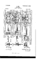
- Figure I is a top plan illustrating the roll system employed in operating upon the sides of the flanges and Web of the work and another novel and meritorious roll system employed in operating upon the edges of the flanges. Portions are broken away in this figure to reduce the size of the drawing and to more clearly show the construction.
- Fig. II is a side elevation relative to Fig. I, partlyin section.
- Fig. III is an elevation, mostly in section, on line 111 Ill, Fig. I, illustrating portions of roll system B, and particularly the operative connection between the rolls D and the roll B.
- Fig. IV is a vertical section on line IV IV, Fig. I, looking in the direction of the arrow.
- Fig. V is a vertical section on line V V, Fig.
- Fig. VI is an elevation, partly in section, of a vertically shiftable top guide and mechanism employed in controlling the said guide.
- Fig. VII is an elevation in section on line VII VII, Fig. VI, looking in the direction of the arrow.
- A designates a roll system for rolling the edges of the heads or flanges of the column, beam, or girder, that is hereinafter termed blank, section, work, or product
- B represents a roll system for rolling opposite sides of the flanges or heads and the web of the work.
- the two roll systems B andA are arranged in line, and the rolling or operating surfaces of the rolls of the two systems of .rolls are driven positively and in the direction required to feed in opposite directions alternately.
- the blank is in a suitably-heated condition preparatory to its introduction into the mill, and the work is fed through the mill with its web arranged horizontally.
- the roll system B (see Figs. I, II, and Ill) comprises a top horizontal roll B, a bottom horizontal roll B and two vertical side rolls D and D, arranged at opposite ends,respectively, of the said horizontal rolls.
- Roll B is arranged horizontally and transversely of the works path in position to operate upon the upper side of the web of the work and upon the inner sides of the works flanges or heads above the web.
- Roll B is arranged below and transversely of the works path in position to operate upon the lower side of the works web and upon the inner sides of the works heads or flanges below the web.
- the two upright rolls D and D are arranged at opposite sides, respectively, of the works path, in position to operate upon the outer side of the adjacent flange or head of the work.
- the Work 0 is shown in position in Figs. II, III, IV, and V.
- the roll system A comprises a pair of rolls 1 and 1 and another pair of rolls 2 and 2.
- the two pairs of rolls are arranged side by side and a short distance apart, and the pair of rolls 2 and 2 is arranged between the pair of rolls 1 and 1 and the pair of web-reducing rolls B B of roll system B.
- Rolls 1 and 1 are arranged at the top and bottom, respectively, of the works path.
- the roll 1 is arranged in position to operate upon the clownflanges or heads.
- Rolls 2 and 2 are arranged at the top and bottom, respectively, of the works path. Roll 2 is arranged in position to operate upon the upwardly presented edges of the works The roll 2 is arranged to afford bearing or resistance for preventing downward displacement of the work during the operation of the roll 2.
- Feed-tables (not shown) of any approved construction are provided at opposite ends of the works path through the mill, and any suitable intervening supports for the work, in addition to the support afforded by the aforesaid rolls, may be provided.
- the work is passed in opposite directions alternately, as already indicated.
- the mechanism or apparatus preferably employed for positively driving the aforesaid rolls comprises the following: An engineshaft 4 is operatively provided with a gear 5, that is operatively connected in any suitable manner with the trunnion of the bottom webreducing roll B and the said gear meshes with a diametrically-corresponding gear 6, that is operatively connected in any approved manner with the adjacent trunnion of the top web-reducin g roll. Hence the two web-reducing rolls are driven at the same speed and in opposite directions, respectively.
- the engine-shaft is operatively provided also with a bevel-gear 7, that meshes with a bevel-gear 8, operatively mounted upon a suitably-supported shaft 9, that is arranged horizontally and at right angles to the engine-shaft, and operatively provided also with bevel-gears 10 and 11.
- Gear 10 meshes with a bevel-gear l2, operatively mounted upon a suitably-supported shaft 13, that is arranged horizontally and parallel with the engine-shaft, and is operatively connected in any manner with a trunnion of roll 2, and the adjacent trunnion of roll 2 is operatively connected in any approved manner with the gear 15, that meshes with a gear 14, operatively mounted upon the shaft 13.
- the gear 11 meshes with the bevelgear 16, operatively mounted upon the suitably-supported shaft 17, that is arranged horizontally and parallel with the shafts 13 and 4 and operatively connected in any suitable manner with a trunnion of roll 1, and the adjacent trunnion of roll 1 is operatively connected in any approved manner with the gear 19, that meshes with the gear 18, operatively mounted upon the shaft 1'7.
- the arrangement of the parts that establish operative connection between the said rolls and the engineshaft is such that all of the said pairs of rolls shall be driven in the direction required to feed the work in the one direction or the other, according as the engine-shaft is driven in the one or the other direction. It will be observed, therefore, that the two web-reducing rolls B and B are driven in opposite directions, re-
- the upper web-reducing roll and the lower web-reducing roll are driven in the same direction as the upper rolls and lower rolls, respectively, of the roll system A; that the work can be fed from and between the rolls of the pairs of rolls of the roll system A to and between the rolls of roll system B, or vice versa, according as the engine-shaft is rotated in the one direction or the other, and preferably the relative arrangement of the two roll systems and the relative arrangement of the two pairs of rolls of the flange-edge-rolling rolls are such as will enable the work, in the latters passage through the mill, to be operated upon by another pair of rolls before it has left an operating pair of rolls.
- the lower web-reducing roll B is suitably supported from the two housings G G, that are arranged a suitable distance apart at opposite sides, respectively, of the works path. It is obvious that for work of the character indicated one or both of the web-reducing rolls must be adjustable vertically, and the upright side rolls D and D must be adjustable apart, and in the case illustrated the top roll B is shiftable vertically. It is obvious also that the rolls at the commencement of the operation of the mill are set as required for the first pass of the heated blank.
- a suitable operative connection between each of the upright rolls D and D and the adjacent trunnion of the upper horizontal roll B comprises, preferably, a horizontal friction-disk d, (see Fig. 1H,) operatively connected with the respective upright roll in any approved manner, and preferably by the engagement of lugs (1 formed upon and depending from the disks d into recesses D formed in the roll, and friction-disks cl are frictionally engaged by friction-collars B formed upon or operatively connected with the trunnions of the roll B.
- the vertical adjustability of disks d accommodates the maintenance of frictional engagement between the said disks and the friction-collars B
- the arrangement of the frietionally-engaging surfaces of members d and B is such that a desirable adequacyin the eontactismaintained between the said friction members during the adjustment of the vertical side rolls toward and from the horizontal rolls and during the adjustment of the top web-reducing roll toward and from the lower web-reducing roll.
- the means acting to elevate each frictiondisk 01 and maintain frictional engagement between the disk and the engaging frictioncollar B comprises, preferably, a piston E, that is secured to the disk in any approved manner.
- the piston extends downwardly into the chamber f, formed in a suitably-supported slide II, that carries the side roll D,
- each side roll D is carried by a slide H.
- the slides H H are movable toward and from each other, and consequently the two rolls D D are adjustable toward and from each other.
- the upright screws L L (see Fig. III) e11- gage correspondingly-threaded nuts L fixed or formed in the tops of housings G G.
- Saddles Z are interposed between the lower ends of said screws and the trunnions of the said roll.
- the trunnions of the top roll have bearing in boxes Z, that rest upon vertically-movable frames or structures Z engaged and held in the desired adjustment by the pistons Z of hydraulic cylinders Z and thereby supportingthe roll at the desired elevation cont-rolled by the screws L.
- the two rolls of each pair of rolls 1 1 and 2 2 of roll system A are of course arranged in the same vertical plane.
- each of the said pairs of rolls is adjustable vertically and has its trunnions resting in boxes A movable up and down in upright housings A A that are arranged at opposite sides, respectively, of the works path. Boxes A rest upon and are consequently supported from vertically-movable frames or structures A engaged and held at the desired elevation by the pistons A of hydraulic cylinders A and thereby supporting the roll at the desired elevation controlled by suitably-operated screws.
- the lower roll 2 of the pair of rolls 2 and 2 is suitably supported from the two housings of the said pair of rolls.
- the lower roll 1 of the pair of rolls 1 1 is adjustable vertically and has its trunnions resting in boxes A that are movable up and down in the upright housings of the said rolls, and each of the said boxes rests upon and is consequently supported from a vertical orupright screw 40, (see Figs. II and V,) that extends through and engages a stationary nut A.
- the screws 20, that are instrumental in vertically adj usting the upper roll of the pair of rolls 1 and 1, are, when they are simultaneously rotated or turned, operated uniformly, and the screw-turning mechanism for the said screws comprises, preferably, two corresponding worm-wheels 21 21, operatively mounted on the different screws, respectively, above the housings and meshing with corresponding worms 22, that are formed upon a horizontally-arranged shaft 23, suitably supported above and from the housings.
- the screws 30, that are instrumental in vertically adjusting the upper roll of the pair of rolls 2 and 2", are, when they are simultaneously rotated or turned, operated uniformly, and the screw-turning mechanism for the said screw comprises, preferably, two corresponding worm-wheels 31 31, operatively mounted on the different screws, respectively, above the housings and meshing with corresponding worms 32, that are formed upona horizontally-arranged shaft 33,suitably supported above and from the housings.
- the screws 40 that are instrumental in vertically adjusting the lower roll of the pair of rolls 1 and 1', are, when they are simultane ously rotated or turned, operated uniformly, and the screw-turning mechanism for the said screws com prises, preferably,two corresponding worm-wheels 41 41, operatively mounted on the different screws, respectively, and meshing with corresponding worms 42,formed upon a horizontally-arranged shaft 43, that is supported in any approved manner.
- the operative connection between screws 20, 80, and 40 and the connected worm-wheels is exactly like the operative connection between screws L and worm-wheels L, so that each of the said screws 20, 30, and 40 is shiftable endwise independently of the connected worm-wheel without interrupting operative connection between the wheel and the screw.
- Theshaft 43 is operatively provided (see Figs. I and II) with a bevel-gear 44, that meshes with a bevel-gear 45, operatively mounted upon a suitably-supported shaft 46, that is arranged horizontally and at right angles to the shaft 43.
- Shaft 46' is operatively provided with another bevelgear 47, that meshes with a bevel-gear 48, operatively mounted upon the lower end of a vertical shaft 49, that is arranged at one end of the pair of rolls 2 and 2, that is operatively provided at its upper end with a bevel-gear 50,that meshes with a bevel-gear 51, operatively mounted upon the Worm-shaft 33, that is instrumental, as already indicated, in the operation of the screws employed for shifting the roll 2.
- the screws 20, 30, and 40 have the same pitch, and the gears of the operative connection between the wormshafts l3 an d 33 correspond diametrically, and the worms and the worm-wheels of the mechanism for driving the screws 30 correspond, respectively, with the worms and worm-wheels of the mechanism employed in the rotation of the screws 40,and consequently all of the screws are capable of being simultaneously shifted at the same speed, so that the rolls 1 and 2 are shift-able simultaneously and at the same speed, and the arrangement of the screws and the parts of the mechanism employed in transmitting motion to the screws is such that the rolls 1 and 2 are, when moved simultaneously by the screws, shifted in opposite directions, respectively.
- a clutch 52 (see Fig. 11,) of any approved construction, is interposed in the line of the shaft -19 and is adapted to interrupt and establish continuity in the said shaft, so that the rolls 1 and 2 can be shifted not only together, but independently of each other.
- the worm-shaft 33 (see Fig. I) is operatively provided with a bevel-gear 29, that is in mesh with a bevel-gear 28, operatively mounted upon a shaft 27, suitably supported at the top of the roll system A and arranged horizontally and at right angles to the wormshafts 33 and 23.
- the said shaft 27 is operatively provided also with a bevel-gear 25, that meshes with a bevel gear 2%, operatively mounted upon the worm-shaft All of the gears of the operative connection between the two worm-shafts and 23 correspond diametrically, and the worms and worm-wheels that are instrumental in shifting the roll 1 correspond with the worms and worm-wheels, respectively, of the mechanism employed in shifting the roll 2, so that the said rolls 1 and 2 are capable of being shifted simultaneously and at an equal speed.
- a clutch 26, capable of establishing and interrupting continuity in the shaft n7, is interposed in the line of the said shaft, and consequently the roll 1 can not only be shifted simultaneously with, but also independently of, the roll 2.
- the bevel-gear 29 of the worm-shaft 33 meshes also with a dian1etrieally-corresponding bevel-gear 35L that is operatively mounted upon the suitably-supported shaft 36, extending from over the roll system A to and over the roll system B into suitable proximity to the worm-shaft M of the last-mentioned roll system and operatively provided with another bevel-gear 37, that meshes with a bevelgear 38, which in the case illustrated has twice the diametrical size of gear 37 and is operatively mounted upon the worm-shaft M.
- the shaft 36 and connected mechanism,upon the transmission of motion to the said mechanism by the latters operative connection with the wormshaft M, are actuated twice as rapidly as the said worm-shaft, and one or more or all of the shiftable rolls 1, l, and 2 are capable of being shifted simultaneously with and twice as rapidly as the upper web-reducing roll if the worm-wheels and pitch of the Worms of the mechanism instrumental in shifting the said web-reducing roll correspond, as they do in the case illustrated, with the worm-wheels and pitch of the worms, respectively, of the roll system A.
- a suitably-operated clutch 39 of any approved type for establishing and interrupting continuity in the shaft 36 is interposed in the line of the said shaft, and consequently the shif'table rolls of the roll system A can be shifted simultaneously with or independently of the shifting of the top roll B of the roll system B.
- the worm-shaft M is intergeared at any convenient point, as at m with the shaft m of an electric motor m.
- the worm-shaft 33 is intergeared at any convenient place, as at m with the shaft 72 of an electric motor 12.
- any one of the shiftable rolls can be shifted simultaneously with or independently of any of the other shiftablc rolls.
- the operation of the mill illustrated is as follows:
- the rolls of the roll system B are set as required to readily receive the blank or section that is. to be rolled and that is transferred to the said roll system directly from a bloomingmill or heating furnace (not shown) and enters the said roll system after passing through the roll system A.
- the latters shiftable rolls are at this time so placed that the centers of the top rolls 1 and 2 of the roll system A are as much higher than the center of the top web-reducing roll B of roll system 13 as the web of the blank or section that is to be rolled by the mill is thicker before entering the roll system B than it is after its first pass through the said roll system B.
- the piece under manipulation goes through the roll system A upon its first pass without being affected by the rolls of the said roll system A.
- the mill is designed in the case illustrated to reduce the web in its roll system B exactly as much in the second pass, fourth pass, sixth pass, eighth pass, and tenth pass (if so manypasses are needed) as the web is reduced in the first, third, fifth, seventh, ninth, and eleventh passes.
- Clutches 39 and 26 are rendered operative simultaneously with the said motor, so that the rolls 1 and 2 of roll system A are shifted simultaneously with the shifting of the roll Bof roll system B and into position required for the second pass'of the work. While motor m and clutches 39 and 26 are operative motor n and clutch 52 are kept inoperative.
- the shiftable rolls of roll system A are shifted twice as rapidly as the shifting of the roll B of roll system B, and consequently the shiftable rolls 1 and 2 during their adjustment simultaneously with the roll B" are shifted as much by one operation of their shifting mechanism as the said roll B is shifted by two operations of its shifting mechanism, and therefore if the centers of rolls 2 and 1 are as much higher than the center of roll B as one-half of the distance that the said rolls 1 and 2 are shifted during one operation of their shifting mechanism, as is the fact in the case illustrated, it will be observed that.
- motor m and clutches 39 and 26 are rendered inoperative. Electric. connections and appliances whereby motor m and clutches 39 and 26 can be simultaneously operated are so well known that illustration thereof in this ap plication is not considered necessary.
- the distance that the roll 2 is lowered determines the amount that the width of the flanges of the work or section is reduced, and this amount will equal the distance that the roll 1 is raised plus the distance that the roll 1 is lowered.
- the section or piece under manipulation is passed through roll systems A and B.
- the thickness of the web is reduced to the amount of space between rolls B and B
- the thickness of the flanges is reduced to the amount of space between the side rolls D D and the ends of rolls B and
- the width of flanges above the web is determined by the distance between rolls 2 and 2.
- the width of flanges below the web is determined by the distance between rolls 1 and 1. same level.
- the roll 1 is on the same level with the roll B whenever roll system A is Working on the edges of the flanges.
- the said roll system A operates only in the case illustrated on the second, fourth, sixth, eighth, and tenth passes, if so many passes are needed, whereas roll system B operates upon every pass.
- the third time motorm is again rendered operative; but on this, as on the fifth, seventh, ninth, and eleventh passes, the clutches 39 and 26 are inoperative, and hence no work is done by roll system A during the said passes.
- the section or piece is then passed through the third time and in this pass is operated upon by roll system B only.
- Next motor at and clutch 52 are again rendered inoperative, and the section or piece is passed through the mill for the fourth time and is reduced in thickness of web and flanges by roll system B and in Width of flanges by roll system A, and this operation is repeated on the sixth, eighth, and tenth passes.
- mill illustrated flanges may be reduced to any width at will by the action of motor n, which, lowering the top roll 2 and at the same time raising bottom roll 1, narrows the flanges above the web by and between rolls 2 and 2 and narrows the flanges below the web by and between rolls 1 and 1. It is evident also, as already indicated, that before the second, fourth, sixth, eighth, and tenth passes (the passes during which work is done upon the edges of the flanges) roll 1 is level with roll B, roll 2 is level with roll B and roll 2 is always the same distance from roll 2 that roll 1 is from roll 1.
- Bottom guides (not shown) for preventing downward displacement of the work during the mills operation and side guides (not shown) for preventing lateral displacement f the work should be provided, but such guides form no part of the present invention and are therefore not illustrated in this application.
- the top guide T for preventing upward displacement of the worlcas the latter passes from roll system B to rolls 2 and 2 of roll system A is provided and is shiftable simultaneously and in unison with the roll B.
- a top guide 80 for preventing upward displacement of the work as the latter passes from rolls 2' and 2 to .rolls 1 and 1 is providedan d is shiftable simultaneously and in unison with the roll 2.
- the object of a top guide in the places indicated is necessary or desirable for the successful operation of a mill of the character indicated, and the guide should be shifted simultaneously with the respective top roll and to the same extent and in the same direction as the roll.
- Top guide T is therefore elevated and lowered simultaneously and in harmony with the elevation and lowering of the roll B, and the arrangementof the guide relative to the roll is such that the lower surface of the guide is approximately flush with the rolls lower extremity.
- the guide T is arranged, furthermore, centrally between the two housings G G and above the path of the Web of the work and is supported in any approved manner from a vertically-movable slide T that extends between the two housings and engages slideways 66, formed in and extending up and down the housings.
- the slide in the case illustrated consists of two parallel bars and 61, that engage the slideways, and blocks or pieces 62, interposed between and suitably secured to the end portions of the bars 60 and (31 and forming a space 63 between the said bars for accommodating the location of collars and nuts (it and 65, respectively, that are mounted upon the lower ends of the vertical screws 70, that are turnably attached to the upper bar 60.
- Two parallel bars and 61 that engage the slideways, and blocks or pieces 62, interposed between and suitably secured to the end portions of the bars 60 and (31 and forming a space 63 between the said bars for accommodating the location of collars and nuts (it and 65, respectively, that are mounted upon the lower ends of the vertical screws 70, that are turnably attached to the upper bar 60.
- Each screw has an annular shoulder 71, resting upon the upper side of the bar (50, and is reduced diametrically below the said shoulder and extends downwardly loosely through the said bar, and a nut (55 is mounted upon the lower end of the screw below the said bar, and a collar or washer 6% is interposed between the nut and the bar.
- Each screw 70 extends upwardly through and engages a nut 67, formed upon or rigid with the adjacent housingthat is, two nuts 67 and (37, that are fixed to the different housings, respectively.
- each screwahove the engaging nut is operatively provided with a suitablysupported worm-wheel 72, that meshes with a worm 73, formed upon the shaft 74, that is arranged horizontally and extends between and through the housings and has bearing in boxes 68, secured to or formed upon the outer sides of the housings.
- the operative connection between eachserew 70 and the engaging worm-wheel is such that the screw can move endwise independently of the worm- ⁇ yl gel, and in the ease illustrated the upper portions of the screws are angular and extend easily through correspondingly-angular axial bores in the said wheels.
- a sprocket-wheel is operatively mounted upon the shaft 74: between the two worms 73 and 73 and is operatively connected by a chain 76 with a sprocket-wheel 77, that is operatively mounted upon the worm-shaft- M.
- the arrangement of parts is such that by the operative connection between the guide T and the wormshaft M hereinbefore described the guide is lowered or elevated, according as the roll B is lowered or elevated, by power transmitted from the shaft M, and the guide and the roll aresimultaneouslyshifted.
- a counterbalance for the guides portion that extends between the slide T and the roll B is provided, and consists of a weight or poise T that is connected with the said portion of the slide by a lever and links T and T, respectively, which lever is fulcrumed to the upper bar 00 of the slide and attached by the said links to the counterbalanced portion of the guide.
- the manner of securing the guideT to the slide T comprises the provision at any suitable points longitudinally of bar 61 of the slide of a pair of lugs '78 and 78, arranged at opposite sides, respectively, of the said bar and engaged on top by a plate 79, that extends across and engages the upper side of the bar and is bolted or otherwise secured to the said lugs.
- the guide and its shiftingmechanism are substantially the same as the guide T and the latters shiftin mechanism and suffice it to state, therefore, that the shifting mechanism for the said guide 80 comprises two upright screws and 90, (see Figs. I and 11,) turnably connected to the guide and engaging stationary nuts 87, operatively provided with and movable endwise independently of wormwheels 92, that mesh with worms 93, formed upon a suitably-supported shaft 94, that is operatively connected at 96 with the wormshaft 33, and the arrangement of parts is such that the guide 80 and the roll 2 are shiftable simultaneously and to the same extent and in a corresponding direction. however, the arrangement and wid th required to cause it to extend over the flanges above the web, and hence is arranged at an elevation above the guide T, as shown in the dotted lines, Fig. II.
- a flange-edge-rolling roll arranged to operate upon the flange edges at one side of the web and shiftable toward and from the work; a roll arranged opposite the said flan gerolling roll in position to afford bearing for the work during the operation of the said flange-edge-rolling roll; another flange-edgerolling roll arranged to operate upon the flange edges at the other side of the web and shiftable toward and from the work, and another roll arranged opposite the lastmentioned flange-edge-rolling roll in position to afford bearing for the work during the operation of the said flange-edge-rolling roll.
- a flange-edge-rolling roll arranged to operate upon the flange edges at one side of the web and shiftable toward and from the work; a roll arranged opposite the said flangeedge-rolling roll in position to afiord bearing for the work during the operation of the said
- the guide 80 has,
- flange-edge-rolling roll arranged to operate upon the flange edges at the other side of the web and shiftable toward and from the work, andanother roll arranged opposite the last-mew tioned flange-edge-rolling roll in position to afford bearing for the work during the operation of the said flange-edge-rolling roll, and
- two flange-edge-rolling rolls arranged to operate upon opposite flange edges, respectively, and arranged a suitable distance apart laterally of each other, and shiftable toward andfrom the works path; a roll arranged opposite one of the said flange-edgerolling rolls; another roll arranged opposite the other flange-edge-rolling roll, and mechanism whereby both of the flange-edge-rolling rolls are shiftable simultaneously and equally in opposite directions, respectively.
- two vertically-shiftable flange-edgerolling rolls arranged, respectively, above and below the works path in position to operate upon the edges of the flanges of the work, and arranged, furthermore, a distance apart laterally of each other; a roll arranged oppo-' site one of the said flange-edge-rolling rolls in position to afford bearing for the web of the work, and another roll arranged opposite the other flange-edge-rolling roll in position to afford bearing for the works web.
- two vertically-shiftable flange-edgerolling rolls arranged at the upper side and lower side, respectively, of the works path in position to operate upon the edges of the flanges, and arranged, furthermore, a distance apart laterally of each other; a roll arranged below the top flange-edge-rolling roll in position to afford bearing for the work during the operation of the said flange-edge-rolling roll, and a vertically-shiftable roll arranged above the bottom flange-edge-rolling roll in position to afford bearing for the work during the operation of the last-mentioned flange-edge-rolling roll.
- a vertically-shiftable top flange-edgerolling roll arranged at the upper side of the works path; means acting to elevate the said roll; mechanism for lowering the said roll against the action of the roll-elevating means; a roll arranged below the aforesaid flangeedge-rolling roll in position to afford bearing for the work during the operation of the said flange-edge-rolling roll; another verticallyshiftable flange-edge-rolling roll arranged at the under side of the works path, mechanism for elevating the last-mentioned flange-edgerolling roll,a vertically-shiftable roll arranged above the last-mentioned flange-edge-rolling roll in position to afford bearing for the work during the operation of the said flange-edgerolling roll; means acting to elevate the shiftable bearin g-formin g roll, and mechanism for lowering the last-mentioned roll against the action of the roll-elevating means.
- a vertically-shlftable top flange-edgerolling roll arranged at the upper side of the works path; means acting to elevate the said roll; mechanism for lowering the said roll against the action of the roll-elevating means; a roll arranged below the aforesaid flangeedge-rolling roll in position to afford bearing for the work during the operation of the said flange-edge-rolling roll; another verticallyshift-able flange-edge-rolling roll arranged at the under side of the works path, mechanism for elevating the last-mentioned flange-edgerolling roll,a verticailyshiftable roll arranged above the last-mentioned flange-edge-rolling roll in position to afford bearing for the work during the operation of the said flange-edgerolling roll; means acting to elevate the shiftable bearing-forming roll, and mechanism for lowering the last-mentioned roll against the action of the roll-elevating means, and means for establishing and interrupting
- a vertically-shiftable top flange-edgerolling roll arranged at the upper side of the works path; means acting to elevate the said roll; mechanism for lowering the said roll against the action of the roll-elevating means; a roll arranged below the aforesaid flangeedge-rolling roll in position to afford bearing for the work during the operation of the said flange-edge-rolling roll; another verticallyshiftable flange-edge-rolling roll arranged at the under side of the works path, mechanism for elevating the last-mentioned flange-edgerolling roll,a vertically-shif table roll arranged above the last-mentioned flange-edge-rolling roll in position to afford bearing for the work during the operation of the said flange-edgerolling roll; means acting to elevate the shiftable bearing-forming roll, mechanism for lowering the last-mentioned roll against the action of the roll-elevating means, and means for establishing and interrupting operative connection between
- a roll system comprising a vertically-shiftable top roll arranged to operate upon the upper side of the web and adjacent inner flange sides, a bottom roll arranged to operate upon the lower side of the web and adjacent inner flange sides, two laterally-shiftable side rolls arranged to operate upon the flanges outer sides; of another roll system arranged in suitable proximity to the first-mentioned roll system and comprising the following: a vertically shiftable top roll arranged to operate upon the upwardly-presented flange edges, abearing-forming bottom roll opposite the said top flange-edge-rolling roll, a vertically-shiftable bottom flan ge-edge-rolling roll, arranged to operate upon the downwardlypresented flange edges, and avertically-shiftable bearing-forming top roll arranged opposite the last-mentioned flange-edge-rolling roll, substantially as set forth.
- a roll system comprising a vertically-shiftable horizontal roll and another horizontal roll arranged to operate upon opposite sides, respectively, of the web and upon the inner sides of the flanges, and upright side rolls arranged to operate upon the outer sides of the flanges; of another roll system comprising the following: two vertically-shiftable flange-edgerolling rolls arranged a suitable distance apart laterally of each other and at elevations corresponding, or approximately corresponding, with the elevations of the different web-re ducing rolls, respectively; two bearing-forming rolls arranged opposite the difierent flan ge-ed ge-rollin g rolls,respectively, and that bearing-affording roll whose elevation, corresponds, or approximately corresponds, with the elevation of the aforesaid shiftable webredueing roll being shiftable vertically, and mechanism or apparatus whereby is attainable the simultaneous shifting of the shiftable bearing-forming roll and the flan ge-edgerolling roll whose elevation corresponds,
- a roll system comprising a vertically-shiftable horizontal roll and another horizontal roll arranged to operate upon opposite sides, respectively, of the web and upon the inner sides of the flanges, and other rolls arranged to operate upon the outer sides of the flanges; another roll system comprising two vertically-shiftable flangeedge-rolling rolls arranged a suitable distance apart laterally of each other and at elevations corresponding, or approximately corresponding, with the elevations of the diiferent webreducing rolls, respectively, and two bearingforming rolls arranged opposite the different fiange-edge-rolling rolls, respectively, and the bearing-forming roll whose elevation corresponds, or approximately corresponds, with the elevation of the shiftable web-reducing roll being shiftable vertically, and mechanism or apparatus whereby is attainable, first, the simultaneous shifting of the shiftable webreducing roll, the shiftable bearing-forming roll, and the flange-edge-rolling roll whose elevation corresponds, or approximately corresponds,with the elevation of the shiftable bear ing-
- a roll system comprising a vertically-shiftable horizontal roll and another horizontal roll arranged to operate upon opposite sides, respectively, of the web and upon the inner sides of the flanges, and other rolls arranged to operate upon the outer sideswof the flanges; another roll system comprising two verticallyshiftable flangeedge-rolling rolls arranged a suitable distance apart laterally of each other and at elevations corresponding, or approximately corresponding, with the elevations of the different webreducing rolls, respectively, and two bearingforming rolls arranged opposite the different flange-'edge-rollin g rolls, respectively, and the bearing-forming rolls whose elevations correspond, or approximately correspond,with the elevation of the shiftable web-reducing roll being shiftable vertically, and mechanism or apparatus whereby is attainable, first, the simultaneous shifting of the shiftable web-reducing roll, the shiftable bearing-forming roll, and the flange-edge-rolling roll whose elevation corresponds, or approximately corresponds, with the elevation of the shiftable bearing-forming
- a roll system comprising a vertically-shiftable horizontal roll and another horizontal roll arranged to operate upon opposite sides, respectively, of the web and upon the inner sides of the flanges, and other rolls arranged to operate upon the outer sides of the flanges; another roll system comprising two vertically-shiftable flangeedge-rolling rolls arranged a suitable distance apart and laterally of each other and at elevations corresponding, or approximately corresponding, with the elevations of the different web-reducing rolls, respectively, and two bearing-forming rolls arranged opposite the different flange edge rolling rolls, respectively, and the bearing-forming rolls,whose elevations correspond, or approximately correspond, with the elevation of the aforesaid shiftable web-reducing roll being shiftable Vertically, and mechanism or apparatus whereby is attainable, first, the simultaneous shifting of the shiftable Web-reducing roll, the shiftable bearing-forming roll, and the flange-edge-rolling roll whose elevation corresponds, or approximately corresponds, with the elevation of the shiftable
- a roll system comprising a Vertically-shiftable horizontal roll and another horizontal roll arranged to operate upon opposite sides, respectively, of the web and upon the inner sides of the flanges, and other rolls arranged to operate upon the outer sides of the flanges; another roll system comprising two Vertically-shiftable flangeedge-rolling rolls arranged a suitable distance apart laterally of each other and at elevations corresponding, or approximately corresponding, with the elevation of the different webreducing rolls, respectively, and two bearingforming rolls arranged opposite the different flange-edge-rollin g rolls, respectively, and the bearing-forming roll whose elevation corresponds, or approximately corresponds, with the elevation of the shiftable web-reducing roll being shiftable vertically; mechanism instrumental in shifting the shiftable web-reducing roll and comprising a suitably-driven shaft; mechanism instrumental in shifting the flange-edge-rolling roll whose elevation corresponds, or approximately corresponds, with the elevation of the shiftable web-reducing roll and comprising
- a roll system comprising a vertically-shiftable top roll arranged to operate upon one side of the web and upon the adjacent inner sides of the flanges, a bottom roll arranged to operate upon the other side of the web and adjacent inner sides of the flanges, and two side rolls arranged to 0perate upon the flanges outer sides;
- another roll system comprising a vertically-shiftable top flange-edge-rolling roll, a bearing-forming roll arranged opposite the said flangeedge-rolling roll, a vertically-shiftable bottom flange-ed ge-rolling roll, and a vertically-shi ftable top bearing-aifording roll opposite the last-mentioned flange-ed re-rolling roll, and mechanism or apparatus whereby is attainable, first, the shifting of all of the top rolls simultaneously, and, secondly, the shifting of the flange-edge-rolling rolls simultaneously butindependently of the remaining rolls, substantially as
- a roll system comprising a vertically-shiftable top roll arranged to operate upon one side of the web and upon the adjacent inner sides of the flanges, a bottom roll arranged to operate upon the other side of the web and adjacent inner sides of the flanges, and two side rolls arranged to operate upon the flanges outer sides;
- another roll system comprising a vertically-shiftable top flange-edge-rolling roll, a bearing-forming roll arranged opposite the said flangeedge-rolling roll, a vertically-shift'able bottom flange-edgc-rolling roll, a vertical]y-shiftable top bearing-forming roll opposite the lastmentioned flange-edge-rolling roll, and mechanism or apparatus whereby is attainable, first, the shifting of all of the top rolls simultaneously and the shifting of the top ilange-edge-rolling roll and the top bearingaifording roll twice as rapidly as the top webreducing roll, and, secondly,
- the combination with a verticallyshiftable top reducing-roll comprising a suitably-rotated shaft; of a top guide arranged to prevent upward displacement of the work and shiftable vertically; upright screws turnably attached to the guide; nuts engaging the screws and formed upon orrigid with the housings; worm wheels upon the screws; such an operative connectionbetween the wheels and the screws as will accommodate an endwise shifting of the screws independently of the wheels without interrupting the said operative connection; suitably-supported worms engaging the said wheels and operatively connected with the aforesaid shaft, and the arrangement of the parts being such that the guide is shifted simultaneously with the shifting of the roll and in a corresponding direction upon the ro-.
Landscapes
- Engineering & Computer Science (AREA)
- Mechanical Engineering (AREA)
- Reduction Rolling/Reduction Stand/Operation Of Reduction Machine (AREA)
Description
No. 635,382. 9 Patented Oct, 24, I899. H. GREY.
\ ROLLING. MILL.
(Application and Jan. 14, 1899.)
(No'ModaL) 4 Sheets-Sheet I.
WITNESSES: mvs/vr n Q A rronws S m: norms PETERS co, Pnmou'mm. wumunfom B4 c.
No. 635,382. Patented Oct. 24, l899.-
H. GREY.
ROLLING MILL.
(Application filed Jan. 14, 1899.) (No Modal.)
4 Sheets-Sheet 2,
25 [CT H H l WITNESSES INVE/Vg OF- Patented Oct; 24; I899.-
4 Sheets-Sheet 3.
:k \m I l 7 H. GREY.
ROLLING MILL (Application filed Ian. 14, 1699.)
Tm: mums PETERS 50.. PNOTD-LITHlZ. wuumowm g. c.
. I :0 I. X r 5 R a v0.
Pa cented on. 24,1899.
4 Sheets-Sheet 4.
(No Model.)
/NVE'NTOH Liv ATTORNE YJ 11m}- w. V II RM m I WITNESSES mmgslz,
' NIT ED STAT/ES Fries.
PATENT HENRY GREY, OF NEW YORK, N.- Y., ASSIGNOR TO THE AMERICAN UNIVERSAL HILL COMPANY, OF SAME PLACE.
ROLLING-MILL.
SPECIFICATION forming part of Letters Patent N 0. 635,382, dated October 24, 1 899. Application filed January 14, 1899. Serial No. 702,165. (No model.)
To all whom. it mayconcern:
Be it known that I, HENRY GREY, residing in the city of New York, county of New York,
to be a full, clear, and exact description of the invention, such as will enable others skilled in the art to which it pertains to m ake and use the same.
This invent-ion relates to improvements in mills or apparatus for rolling metallic beams, girders, columns, and structural work generally.
The primary object of this invention is to obviate the necessity of employing different roll-collars or rolls in rolling different widths of flanges, and thereby avoid the labor and loss of time whenever a change in the width of flanges for any given weight of beam or work is desired, and to obviate the necessity of turning the blank or work during the process of manufacture, and thereby prevent loss of heat during the process.
With this object in view, and to the end of providing novel and meritorious means for preventing upward displacement of the work, and realizing other advantages hereinafter appearing, the invention consists in certain features of construction and combinations of parts hereinafter described, and pointed out in the claims.
In the accompanying drawings, Figure I is a top plan illustrating the roll system employed in operating upon the sides of the flanges and Web of the work and another novel and meritorious roll system employed in operating upon the edges of the flanges. Portions are broken away in this figure to reduce the size of the drawing and to more clearly show the construction. Fig. II is a side elevation relative to Fig. I, partlyin section. Fig. III is an elevation, mostly in section, on line 111 Ill, Fig. I, illustrating portions of roll system B, and particularly the operative connection between the rolls D and the roll B. Fig. IV is a vertical section on line IV IV, Fig. I, looking in the direction of the arrow. Fig. V is a vertical section on line V V, Fig. I, looking in the direction of the arrow. Fig. VI is an elevation, partly in section, of a vertically shiftable top guide and mechanism employed in controlling the said guide. Fig. VII is an elevation in section on line VII VII, Fig. VI, looking in the direction of the arrow.
Referring to the drawings, A designates a roll system for rolling the edges of the heads or flanges of the column, beam, or girder, that is hereinafter termed blank, section, work, or product, and B represents a roll system for rolling opposite sides of the flanges or heads and the web of the work.
The two roll systems B andA are arranged in line, and the rolling or operating surfaces of the rolls of the two systems of .rolls are driven positively and in the direction required to feed in opposite directions alternately. The blank is in a suitably-heated condition preparatory to its introduction into the mill, and the work is fed through the mill with its web arranged horizontally.
The roll system B (see Figs. I, II, and Ill) comprises a top horizontal roll B, a bottom horizontal roll B and two vertical side rolls D and D, arranged at opposite ends,respectively, of the said horizontal rolls. Roll B is arranged horizontally and transversely of the works path in position to operate upon the upper side of the web of the work and upon the inner sides of the works flanges or heads above the web. Roll B is arranged below and transversely of the works path in position to operate upon the lower side of the works web and upon the inner sides of the works heads or flanges below the web. The two upright rolls D and D are arranged at opposite sides, respectively, of the works path, in position to operate upon the outer side of the adjacent flange or head of the work. The Work 0 is shown in position in Figs. II, III, IV, and V.
The roll system A comprises a pair of rolls 1 and 1 and another pair of rolls 2 and 2.
The two pairs of rolls are arranged side by side and a short distance apart, and the pair of rolls 2 and 2 is arranged between the pair of rolls 1 and 1 and the pair of web-reducing rolls B B of roll system B. Rolls 1 and 1 are arranged at the top and bottom, respectively, of the works path. The roll 1 is arranged in position to operate upon the clownflanges or heads.
wardly-presented edges of the work, and the roll 1 is arranged to afford bearing or resistance for preventing upward displacement of the work during the operation of the roll 1. Rolls 2 and 2 are arranged at the top and bottom, respectively, of the works path. Roll 2 is arranged in position to operate upon the upwardly presented edges of the works The roll 2 is arranged to afford bearing or resistance for preventing downward displacement of the work during the operation of the roll 2.
Feed-tables (not shown) of any approved construction are provided at opposite ends of the works path through the mill, and any suitable intervening supports for the work, in addition to the support afforded by the aforesaid rolls, may be provided. The work is passed in opposite directions alternately, as already indicated.
The mechanism or apparatus preferably employed for positively driving the aforesaid rolls comprises the following: An engineshaft 4 is operatively provided with a gear 5, that is operatively connected in any suitable manner with the trunnion of the bottom webreducing roll B and the said gear meshes with a diametrically-corresponding gear 6, that is operatively connected in any approved manner with the adjacent trunnion of the top web-reducin g roll. Hence the two web-reducing rolls are driven at the same speed and in opposite directions, respectively. The engine-shaft is operatively provided also with a bevel-gear 7, that meshes with a bevel-gear 8, operatively mounted upon a suitably-supported shaft 9, that is arranged horizontally and at right angles to the engine-shaft, and operatively provided also with bevel-gears 10 and 11. Gear 10 meshes with a bevel-gear l2, operatively mounted upon a suitably-supported shaft 13, that is arranged horizontally and parallel with the engine-shaft, and is operatively connected in any manner with a trunnion of roll 2, and the adjacent trunnion of roll 2 is operatively connected in any approved manner with the gear 15, that meshes with a gear 14, operatively mounted upon the shaft 13. The gear 11 meshes with the bevelgear 16, operatively mounted upon the suitably-supported shaft 17, that is arranged horizontally and parallel with the shafts 13 and 4 and operatively connected in any suitable manner with a trunnion of roll 1, and the adjacent trunnion of roll 1 is operatively connected in any approved manner with the gear 19, that meshes with the gear 18, operatively mounted upon the shaft 1'7. The arrangement of the parts that establish operative connection between the said rolls and the engineshaft is such that all of the said pairs of rolls shall be driven in the direction required to feed the work in the one direction or the other, according as the engine-shaft is driven in the one or the other direction. It will be observed, therefore, that the two web-reducing rolls B and B are driven in opposite directions, re-
spectively, as already indicated; that the upper web-reducing roll and the lower web-reducing roll are driven in the same direction as the upper rolls and lower rolls, respectively, of the roll system A; that the work can be fed from and between the rolls of the pairs of rolls of the roll system A to and between the rolls of roll system B, or vice versa, according as the engine-shaft is rotated in the one direction or the other, and preferably the relative arrangement of the two roll systems and the relative arrangement of the two pairs of rolls of the flange-edge-rolling rolls are such as will enable the work, in the latters passage through the mill, to be operated upon by another pair of rolls before it has left an operating pair of rolls.
The lower web-reducing roll B is suitably supported from the two housings G G, that are arranged a suitable distance apart at opposite sides, respectively, of the works path. It is obvious that for work of the character indicated one or both of the web-reducing rolls must be adjustable vertically, and the upright side rolls D and D must be adjustable apart, and in the case illustrated the top roll B is shiftable vertically. It is obvious also that the rolls at the commencement of the operation of the mill are set as required for the first pass of the heated blank.
Before further reference to the adjustment of the rolls B, D, and D, I would remark that live surfaces should be present to all sides of the work, and consequently all of said rolls, and the bottom roll B should be rotated positively. A suitable operative connection between each of the upright rolls D and D and the adjacent trunnion of the upper horizontal roll B comprises, preferably, a horizontal friction-disk d, (see Fig. 1H,) operatively connected with the respective upright roll in any approved manner, and preferably by the engagement of lugs (1 formed upon and depending from the disks d into recesses D formed in the roll, and friction-disks cl are frictionally engaged by friction-collars B formed upon or operatively connected with the trunnions of the roll B. The vertical adjustability of disks d accommodates the maintenance of frictional engagement between the said disks and the friction-collars B The arrangement of the frietionally-engaging surfaces of members d and B is such that a desirable adequacyin the eontactismaintained between the said friction members during the adjustment of the vertical side rolls toward and from the horizontal rolls and during the adjustment of the top web-reducing roll toward and from the lower web-reducing roll. The means acting to elevate each frictiondisk 01 and maintain frictional engagement between the disk and the engaging frictioncollar B comprises, preferably, a piston E, that is secured to the disk in any approved manner. The piston extends downwardly into the chamber f, formed in a suitably-supported slide II, that carries the side roll D,
ICC
that is operatively connected with the said disk. The'chamber f is provided with an inlet f, at which fluid under pressure is introduced to the lower end of the piston. This fluid acts to force the piston upwardly, and thereby causes the disk (1 to be held in frictional contact with the engaging friction-collars B and can, if desired, assist in supporting the top roll B. As already indicated, each side roll D is carried by a slide H. The slides H H are movable toward and from each other, and consequently the two rolls D D are adjustable toward and from each other. The
mechanism for shifting the rolls D D toward and from each other and the means employed in maintaining operative connection between the rolls D D and the roll B form no part of the present invention, and further illustration thereof and reference thereto in this application is not considered necessary.
The upright screws L L (see Fig. III) e11- gage correspondingly-threaded nuts L fixed or formed in the tops of housings G G. Saddles Z are interposed between the lower ends of said screws and the trunnions of the said roll. The trunnions of the top roll have bearing in boxes Z, that rest upon vertically-movable frames or structures Z engaged and held in the desired adjustment by the pistons Z of hydraulic cylinders Z and thereby supportingthe roll at the desired elevation cont-rolled by the screws L.
The mechanism employed for rotating screws Lis shown to be as follows: Upon the upper ends or portions of screws L (see Figs. I and III) are operatively mounted corresponding worm wheels L, that mesh with corresponding worms M, formed upon a suitably-supported and suitably-driven horizontally-arranged shaft M. 'The operative connection between each wheel L and the screw is formed by the upper angular portion of the screw extending easily through a correspondingly-angular axial bore formed in the wheel, so as to accommodate an endwise movement of the screw L independently of the wheel without interrupting operative connection between the wheel and the screw. The two rolls of each pair of rolls 1 1 and 2 2 of roll system A are of course arranged in the same vertical plane. The upper roll of each of the said pairs of rolls is adjustable vertically and has its trunnions resting in boxes A movable up and down in upright housings A A that are arranged at opposite sides, respectively, of the works path. Boxes A rest upon and are consequently supported from vertically-movable frames or structures A engaged and held at the desired elevation by the pistons A of hydraulic cylinders A and thereby supporting the roll at the desired elevation controlled by suitably-operated screws. Saddles or blocks A rest upon the trunnions of the roll above half-boxes A and the said screws engage correspondingly-threaded nuts fixed or formed in the tops of the housings and have their lower extremities engaging the upper surfaces of saddles A The lower roll 2 of the pair of rolls 2 and 2 is suitably supported from the two housings of the said pair of rolls. The lower roll 1 of the pair of rolls 1 1 is adjustable vertically and has its trunnions resting in boxes A that are movable up and down in the upright housings of the said rolls, and each of the said boxes rests upon and is consequently supported from a vertical orupright screw 40, (see Figs. II and V,) that extends through and engages a stationary nut A. It will be observed, therefore, that the upper roll of the pair of rolls 2 and 2 and both rolls of the pair of rolls 1 and and 1 are shiftable vertically for the purpose hereinafter made apparent.
The screws 20, that are instrumental in vertically adj usting the upper roll of the pair of rolls 1 and 1, are, when they are simultaneously rotated or turned, operated uniformly, and the screw-turning mechanism for the said screws comprises, preferably, two corresponding worm-wheels 21 21, operatively mounted on the different screws, respectively, above the housings and meshing with corresponding worms 22, that are formed upon a horizontally-arranged shaft 23, suitably supported above and from the housings.
The screws 30, that are instrumental in vertically adjusting the upper roll of the pair of rolls 2 and 2", are, when they are simultaneously rotated or turned, operated uniformly, and the screw-turning mechanism for the said screw comprises, preferably, two corresponding worm-wheels 31 31, operatively mounted on the different screws, respectively, above the housings and meshing with corresponding worms 32, that are formed upona horizontally-arranged shaft 33,suitably supported above and from the housings.
The screws 40, that are instrumental in vertically adjusting the lower roll of the pair of rolls 1 and 1', are, when they are simultane ously rotated or turned, operated uniformly, and the screw-turning mechanism for the said screws com prises, preferably,two corresponding worm-wheels 41 41, operatively mounted on the different screws, respectively, and meshing with corresponding worms 42,formed upon a horizontally-arranged shaft 43, that is supported in any approved manner.
The operative connection between screws 20, 80, and 40 and the connected worm-wheels is exactly like the operative connection between screws L and worm-wheels L, so that each of the said screws 20, 30, and 40 is shiftable endwise independently of the connected worm-wheel without interrupting operative connection between the wheel and the screw.
Theshaft 43 is operatively provided (see Figs. I and II) with a bevel-gear 44, that meshes with a bevel-gear 45, operatively mounted upon a suitably-supported shaft 46, that is arranged horizontally and at right angles to the shaft 43. Shaft 46'is operatively provided with another bevelgear 47, that meshes with a bevel-gear 48, operatively mounted upon the lower end of a vertical shaft 49, that is arranged at one end of the pair of rolls 2 and 2, that is operatively provided at its upper end with a bevel-gear 50,that meshes with a bevel-gear 51, operatively mounted upon the Worm-shaft 33, that is instrumental, as already indicated, in the operation of the screws employed for shifting the roll 2. The screws 20, 30, and 40 have the same pitch, and the gears of the operative connection between the wormshafts l3 an d 33 correspond diametrically, and the worms and the worm-wheels of the mechanism for driving the screws 30 correspond, respectively, with the worms and worm-wheels of the mechanism employed in the rotation of the screws 40,and consequently all of the screws are capable of being simultaneously shifted at the same speed, so that the rolls 1 and 2 are shift-able simultaneously and at the same speed, and the arrangement of the screws and the parts of the mechanism employed in transmitting motion to the screws is such that the rolls 1 and 2 are, when moved simultaneously by the screws, shifted in opposite directions, respectively.
A clutch 52, (see Fig. 11,) of any approved construction, is interposed in the line of the shaft -19 and is adapted to interrupt and establish continuity in the said shaft, so that the rolls 1 and 2 can be shifted not only together, but independently of each other.
The worm-shaft 33 (see Fig. I) is operatively provided with a bevel-gear 29, that is in mesh with a bevel-gear 28, operatively mounted upon a shaft 27, suitably supported at the top of the roll system A and arranged horizontally and at right angles to the wormshafts 33 and 23. The said shaft 27 is operatively provided also with a bevel-gear 25, that meshes with a bevel gear 2%, operatively mounted upon the worm-shaft All of the gears of the operative connection between the two worm-shafts and 23 correspond diametrically, and the worms and worm-wheels that are instrumental in shifting the roll 1 correspond with the worms and worm-wheels, respectively, of the mechanism employed in shifting the roll 2, so that the said rolls 1 and 2 are capable of being shifted simultaneously and at an equal speed.
A clutch 26, capable of establishing and interrupting continuity in the shaft n7, is interposed in the line of the said shaft, and consequently the roll 1 can not only be shifted simultaneously with, but also independently of, the roll 2.
The bevel-gear 29 of the worm-shaft 33 meshes also with a dian1etrieally-corresponding bevel-gear 35L that is operatively mounted upon the suitably-supported shaft 36, extending from over the roll system A to and over the roll system B into suitable proximity to the worm-shaft M of the last-mentioned roll system and operatively provided with another bevel-gear 37, that meshes with a bevelgear 38, which in the case illustrated has twice the diametrical size of gear 37 and is operatively mounted upon the worm-shaft M. It is obvious, therefore, that the shaft 36 and connected mechanism,upon the transmission of motion to the said mechanism by the latters operative connection with the wormshaft M, are actuated twice as rapidly as the said worm-shaft, and one or more or all of the shiftable rolls 1, l, and 2 are capable of being shifted simultaneously with and twice as rapidly as the upper web-reducing roll if the worm-wheels and pitch of the Worms of the mechanism instrumental in shifting the said web-reducing roll correspond, as they do in the case illustrated, with the worm-wheels and pitch of the worms, respectively, of the roll system A.
A suitably-operated clutch 39 of any approved type for establishing and interrupting continuity in the shaft 36 is interposed in the line of the said shaft, and consequently the shif'table rolls of the roll system A can be shifted simultaneously with or independently of the shifting of the top roll B of the roll system B.
The worm-shaft M is intergeared at any convenient point, as at m with the shaft m of an electric motor m. The worm-shaft 33 is intergeared at any convenient place, as at m with the shaft 72 of an electric motor 12.
By the construction hereinbefore described it is obvious that any one of the shiftable rolls can be shifted simultaneously with or independently of any of the other shiftablc rolls.
Those portions of the resisting or bearingaffording rolls 1 and 2' that are adjacent to the roll proper of the said rolls are sufficiently smaller diametrically than the flangeedge-rolling rolls 1 and 2 to avoid contact or interference with the work.
The operation of the mill illustrated is as follows: The rolls of the roll system B are set as required to readily receive the blank or section that is. to be rolled and that is transferred to the said roll system directly from a bloomingmill or heating furnace (not shown) and enters the said roll system after passing through the roll system A. The latters shiftable rolls are at this time so placed that the centers of the top rolls 1 and 2 of the roll system A are as much higher than the center of the top web-reducing roll B of roll system 13 as the web of the blank or section that is to be rolled by the mill is thicker before entering the roll system B than it is after its first pass through the said roll system B. Hence the piece under manipulation goes through the roll system A upon its first pass without being affected by the rolls of the said roll system A. The mill is designed in the case illustrated to reduce the web in its roll system B exactly as much in the second pass, fourth pass, sixth pass, eighth pass, and tenth pass (if so manypasses are needed) as the web is reduced in the first, third, fifth, seventh, ninth, and eleventh passes. After the section or blank has made its first pass through the roll system B upon the sections passage to the latter from roll system A the electric motor m is rendered operative, and the shiftable web-reducing roll B and the rolls D D employed in working upon the outer sides of the flanges are shifted inwardly far enough for the next or second pass. Clutches 39 and 26 are rendered operative simultaneously with the said motor, so that the rolls 1 and 2 of roll system A are shifted simultaneously with the shifting of the roll Bof roll system B and into position required for the second pass'of the work. While motor m and clutches 39 and 26 are operative motor n and clutch 52 are kept inoperative. As already indicated, the shiftable rolls of roll system A are shifted twice as rapidly as the shifting of the roll B of roll system B, and consequently the shiftable rolls 1 and 2 during their adjustment simultaneously with the roll B" are shifted as much by one operation of their shifting mechanism as the said roll B is shifted by two operations of its shifting mechanism, and therefore if the centers of rolls 2 and 1 are as much higher than the center of roll B as one-half of the distance that the said rolls 1 and 2 are shifted during one operation of their shifting mechanism, as is the fact in the case illustrated, it will be observed that. upon the first operation of the shifting mechanism of the said rolls 1 and 2 preparatory to the second pass of the work the centers of the said rolls 1 and '2 and the center of the said shiftable web-r ducing roll B will be on the same "level. When the roll B has been lowered, as
required for the second pass, and when the rolls 1 and 2 have been lowered so as to bring their centers as low as the center of roll B, motor m and clutches 39 and 26 are rendered inoperative. Electric. connections and appliances whereby motor m and clutches 39 and 26 can be simultaneously operated are so well known that illustration thereof in this ap plication is not considered necessary. When the shiftable rolls of roll system B have been set to reduce the thickness of the Web and flanges to the degree required for the second pass and when motor m and clutches 39 and 26 have been rendered inoperative, the motor at and the clutch 52 are rendered operative, so that roll l is shifted toward the opposing bearing-affording roll 1, and simultaneously roll 2 is again shifted toward the opposing bearing-affording roll 2, and both rolls 1 and 2 are by the mechanism illustrated shifted at the same speed. Rolls 1 and 2 are now ready for the second pass, and motor at and clutch 52 are again rendered inoperative. The distance that the roll 2 is lowered determines the amount that the width of the flanges of the work or section is reduced, and this amount will equal the distance that the roll 1 is raised plus the distance that the roll 1 is lowered. Now the section or piece under manipulation is passed through roll systems A and B. The thickness of the web is reduced to the amount of space between rolls B and B The thickness of the flanges is reduced to the amount of space between the side rolls D D and the ends of rolls B and The width of flanges above the web is determined by the distance between rolls 2 and 2. The width of flanges below the web is determined by the distance between rolls 1 and 1. same level. The roll 1 is on the same level with the roll B whenever roll system A is Working on the edges of the flanges. As already indicated, the said roll system A operates only in the case illustrated on the second, fourth, sixth, eighth, and tenth passes, if so many passes are needed, whereas roll system B operates upon every pass. Before the section that is being operated on is passed through the roll system B the third time motorm is again rendered operative; but on this, as on the fifth, seventh, ninth, and eleventh passes, the clutches 39 and 26 are inoperative, and hence no work is done by roll system A during the said passes. The section or piece is then passed through the third time and in this pass is operated upon by roll system B only. Before making the fourth pass clutches 39 and 26 are again rendered operative, so that preparatory to the fourth pass the roll B is lowered as much as it was lowered be- $76 The roll 2 and the roll B are on the L fore the third pass, and rolls 1 and 2 are lowered a distance equal to the descent of the roll B during both third and fourth passes. Then motor m and clutches 39 and 26 are again rendered inoperative, and motor 91 and clutches 52 are rendered operative, and roll 2 and roll 1 are shifted simultaneously and correspondingly toward the opposite bearingaffording roll. Next motor at and clutch 52 are again rendered inoperative, and the section or piece is passed through the mill for the fourth time and is reduced in thickness of web and flanges by roll system B and in Width of flanges by roll system A, and this operation is repeated on the sixth, eighth, and tenth passes.
It must be obvious that by the mill illustrated flanges may be reduced to any width at will by the action of motor n, which, lowering the top roll 2 and at the same time raising bottom roll 1, narrows the flanges above the web by and between rolls 2 and 2 and narrows the flanges below the web by and between rolls 1 and 1. It is evident also, as already indicated, that before the second, fourth, sixth, eighth, and tenth passes (the passes during which work is done upon the edges of the flanges) roll 1 is level with roll B, roll 2 is level with roll B and roll 2 is always the same distance from roll 2 that roll 1 is from roll 1.
Now while a very desirable arrangement and combination of parts is described in this application it should be understood that and without departing from the spirit and scope of the invention the operative connection shown gears 37 and 38 might be omitted and the rollshifting screws of roll system A might be worked independently of the roll-shifting screws of roll system B and independen tly of each other, and instead of reducing exactly as much in every other pass the reduction might be at the will of the operator,who would decide how much the reduction should be in any pass. The primary object of the invention, as already indicated, is to avoid the necessity of changing roll-collars or rolls in the flange-edgerolling roll system for making different widths of flanges and to avoid the necessity of overturning the work. Of course the coupling together of the two roll systems in a manner substantially as indicated in this application is a matter of convenience, but not of primary importance, although at times very desirable.
Bottom guides (not shown) for preventing downward displacement of the work during the mills operation and side guides (not shown) for preventing lateral displacement f the work should be provided, but such guides form no part of the present invention and are therefore not illustrated in this application.
The top guide T for preventing upward displacement of the worlcas the latter passes from roll system B to rolls 2 and 2 of roll system A is provided and is shiftable simultaneously and in unison with the roll B. A top guide 80 for preventing upward displacement of the work as the latter passes from rolls 2' and 2 to . rolls 1 and 1 is providedan d is shiftable simultaneously and in unison with the roll 2. The object of a top guide in the places indicated is necessary or desirable for the successful operation of a mill of the character indicated, and the guide should be shifted simultaneously with the respective top roll and to the same extent and in the same direction as the roll. Top guide T is therefore elevated and lowered simultaneously and in harmony with the elevation and lowering of the roll B, and the arrangementof the guide relative to the roll is such that the lower surface of the guide is approximately flush with the rolls lower extremity. The guide T is arranged, furthermore, centrally between the two housings G G and above the path of the Web of the work and is supported in any approved manner from a vertically-movable slide T that extends between the two housings and engages slideways 66, formed in and extending up and down the housings. The slide in the case illustrated consists of two parallel bars and 61, that engage the slideways, and blocks or pieces 62, interposed between and suitably secured to the end portions of the bars 60 and (31 and forming a space 63 between the said bars for accommodating the location of collars and nuts (it and 65, respectively, that are mounted upon the lower ends of the vertical screws 70, that are turnably attached to the upper bar 60. Two
screws are provided at opposite end portions, respectively, of the slide. Each screw has an annular shoulder 71, resting upon the upper side of the bar (50, and is reduced diametrically below the said shoulder and extends downwardly loosely through the said bar, and a nut (55 is mounted upon the lower end of the screw below the said bar, and a collar or washer 6% is interposed between the nut and the bar. Each screw 70 extends upwardly through and engages a nut 67, formed upon or rigid with the adjacent housingthat is, two nuts 67 and (37, that are fixed to the different housings, respectively. The screws extend a suitable distance above the nuts, and each screwahove the engaging nut is operatively provided with a suitablysupported worm-wheel 72, that meshes with a worm 73, formed upon the shaft 74, that is arranged horizontally and extends between and through the housings and has bearing in boxes 68, secured to or formed upon the outer sides of the housings. The operative connection between eachserew 70 and the engaging worm-wheel is such that the screw can move endwise independently of the worm-\yl gel, and in the ease illustrated the upper portions of the screws are angular and extend easily through correspondingly-angular axial bores in the said wheels. A sprocket-wheel is operatively mounted upon the shaft 74: between the two worms 73 and 73 and is operatively connected by a chain 76 with a sprocket-wheel 77, that is operatively mounted upon the worm-shaft- M. The arrangement of parts is such that by the operative connection between the guide T and the wormshaft M hereinbefore described the guide is lowered or elevated, according as the roll B is lowered or elevated, by power transmitted from the shaft M, and the guide and the roll aresimultaneouslyshifted. Itisobvious that if, as in the case illustrated, the sprocketwheels 75 and 77 correspond in diameter and the pitch of the screws 70 bears the same relation to the number of teeth on the wormwheels "2 that the pitch of the screws L bears relative to the number of teeth on the wormwheels L the guide T and roll B are equally shifted during the Operation of the shifting mechanism.
A counterbalance for the guides portion that extends between the slide T and the roll B is provided, and consists of a weight or poise T that is connected with the said portion of the slide by a lever and links T and T, respectively, which lever is fulcrumed to the upper bar 00 of the slide and attached by the said links to the counterbalanced portion of the guide.
The manner of securing the guideT to the slide T comprises the provision at any suitable points longitudinally of bar 61 of the slide of a pair of lugs '78 and 78, arranged at opposite sides, respectively, of the said bar and engaged on top by a plate 79, that extends across and engages the upper side of the bar and is bolted or otherwise secured to the said lugs.
The guide and its shiftingmechanism are substantially the same as the guide T and the latters shiftin mechanism and suffice it to state, therefore, that the shifting mechanism for the said guide 80 comprises two upright screws and 90, (see Figs. I and 11,) turnably connected to the guide and engaging stationary nuts 87, operatively provided with and movable endwise independently of wormwheels 92, that mesh with worms 93, formed upon a suitably-supported shaft 94, that is operatively connected at 96 with the wormshaft 33, and the arrangement of parts is such that the guide 80 and the roll 2 are shiftable simultaneously and to the same extent and in a corresponding direction. however, the arrangement and wid th required to cause it to extend over the flanges above the web, and hence is arranged at an elevation above the guide T, as shown in the dotted lines, Fig. II.
What I claim is- 1. In a rolling-mill of the character indicated, two flange-edge-rolling rolls arranged to operate upon opposite flange edges, respectively, screws and engaging nuts instrumental in shifting one of the said rolls; wormwheels operatively mounted upon the said screws in such a manner that the screws can move endwise independently of the wheels; a worm-shaft having worms engaging the said wheels; screws and engaging nuts instrumental in shifting the other roll; worm-wheels operatively mounted upon the last-mentioned screws in such a mannerthat the screws can move endwise independently of the wheels; a worm -shaft having worms engaging the last-mentioned worm-wheels; a shaft operatively connected with both of the said wormshafts, and a clutch arranged in the line of the last-mentioned shaft, and adapted to establish and interrupt continuity in the shaft.
2. In a rolling-mill of the character indicated, a flange-edge-rolling roll arranged to operate upon the flange edges at one side of the web and shiftable toward and from the work; a roll arranged opposite the said flan gerolling roll in position to afford bearing for the work during the operation of the said flange-edge-rolling roll; another flange-edgerolling roll arranged to operate upon the flange edges at the other side of the web and shiftable toward and from the work, and another roll arranged opposite the lastmentioned flange-edge-rolling roll in position to afford bearing for the work during the operation of the said flange-edge-rolling roll.
3. In a rolling-mill of the character indicated, a flange-edge-rolling roll arranged to operate upon the flange edges at one side of the web and shiftable toward and from the work; a roll arranged opposite the said flangeedge-rolling roll in position to afiord bearing for the work during the operation of the said The guide 80 has,
flange-edge-rolling roll; another flange-edgerolling roll arranged to operate upon the flange edges at the other side of the web and shiftable toward and from the work, andanother roll arranged opposite the last-mew tioned flange-edge-rolling roll in position to afford bearing for the work during the operation of the said flange-edge-rolling roll, and
mechanism whereby bothefthe flange-edge rolling rolls are shiftable simultaneously in opposite directions, respectively.
4. In a rolling-mill of the character indicated, two flange-edge-rolling rolls arranged to operate upon opposite flange edges, respectively, and arranged a suitable distance apart laterally of each other, and shiftable toward andfrom the works path; a roll arranged opposite one of the said flange-edgerolling rolls; another roll arranged opposite the other flange-edge-rolling roll, and mechanism whereby both of the flange-edge-rolling rolls are shiftable simultaneously and equally in opposite directions, respectively.
5. In a rolling-mill of the character indicated, two vertically-shiftable flange-edgerolling rolls arranged, respectively, above and below the works path in position to operate upon the edges of the flanges of the work, and arranged, furthermore, a distance apart laterally of each other; a roll arranged oppo-' site one of the said flange-edge-rolling rolls in position to afford bearing for the web of the work, and another roll arranged opposite the other flange-edge-rolling roll in position to afford bearing for the works web.
6. In a rolling-mill of the character indicated, two vertically-shiftable flange-edgerolling rolls arranged at the upper side and lower side, respectively, of the works path in position to operate upon the edges of the flanges, and arranged, furthermore, a distance apart laterally of each other; a roll arranged below the top flange-edge-rolling roll in position to afford bearing for the work during the operation of the said flange-edge-rolling roll, and a vertically-shiftable roll arranged above the bottom flange-edge-rolling roll in position to afford bearing for the work during the operation of the last-mentioned flange-edge-rolling roll.
7. In a rolling-mill of the character indicated, a vertically-shiftable top flange-edgerolling roll arranged at the upper side of the works path; means acting to elevate the said roll; mechanism for lowering the said roll against the action of the roll-elevating means; a roll arranged below the aforesaid flangeedge-rolling roll in position to afford bearing for the work during the operation of the said flange-edge-rolling roll; another verticallyshiftable flange-edge-rolling roll arranged at the under side of the works path, mechanism for elevating the last-mentioned flange-edgerolling roll,a vertically-shiftable roll arranged above the last-mentioned flange-edge-rolling roll in position to afford bearing for the work during the operation of the said flange-edgerolling roll; means acting to elevate the shiftable bearin g-formin g roll, and mechanism for lowering the last-mentioned roll against the action of the roll-elevating means.
8. In a rolling-mill of the character indicated, a vertically-shlftable top flange-edgerolling roll arranged at the upper side of the works path; means acting to elevate the said roll; mechanism for lowering the said roll against the action of the roll-elevating means; a roll arranged below the aforesaid flangeedge-rolling roll in position to afford bearing for the work during the operation of the said flange-edge-rolling roll; another verticallyshift-able flange-edge-rolling roll arranged at the under side of the works path, mechanism for elevating the last-mentioned flange-edgerolling roll,a verticailyshiftable roll arranged above the last-mentioned flange-edge-rolling roll in position to afford bearing for the work during the operation of the said flange-edgerolling roll; means acting to elevate the shiftable bearing-forming roll, and mechanism for lowering the last-mentioned roll against the action of the roll-elevating means, and means for establishing and interrupting operative connection between the aforesaid roll-lowering mechanism.
5). In a rolling-mill of the character indicated, a vertically-shiftable top flange-edgerolling roll arranged at the upper side of the works path; means acting to elevate the said roll; mechanism for lowering the said roll against the action of the roll-elevating means; a roll arranged below the aforesaid flangeedge-rolling roll in position to afford bearing for the work during the operation of the said flange-edge-rolling roll; another verticallyshiftable flange-edge-rolling roll arranged at the under side of the works path, mechanism for elevating the last-mentioned flange-edgerolling roll,a vertically-shif table roll arranged above the last-mentioned flange-edge-rolling roll in position to afford bearing for the work during the operation of the said flange-edgerolling roll; means acting to elevate the shiftable bearing-forming roll, mechanism for lowering the last-mentioned roll against the action of the roll-elevating means, and means for establishing and interrupting operative connection between the mechanism for lowering the top flange-edge-rolling roll and the mechanism instrumental in raising the bottom flange-edge-rolling roll.
10. I11 a rolling-mill of the character indicated a vertically-shiftable top flange-edgerolling roll arranged at the upper side of the works path; means acting to elevate the said roll; mechanism for lowering the said roll against the action of the roll-elevatingmeans; a roll arranged below the aforesaid flangeedge-rolling roll in position to afford bearing for the work during the operation of the said flange-edge-rolling roll; another verticallyshiftable flange-edge-rolling roll arranged at the under side of the works path; mechanism for elevating the last-mentioned flange-edgerolling roll; a vertically-shiftable roll arranged above the last-mentioned flange-edgerolling roll in position to afford bearing for the work during the operation of the said flange-edge-rolling roll; means acting to clevate the shiftablebearing-forming roll; mechanism for lowering the last-mentioned roll against the action of the roll-elevating means, a shaft operatively connected with the aforesaid roll-lowering mechanisms, a clutch for interrupting and establishing continuity in the said shaft; another shaft operatively connected with the mechanism for lowering the top flan ge-ed ge-rollin g roll and with the afore said mechanism instrumental in raising the bottom flange-edge-rolling roll, and a clutch for interrupting and establishing continuity in the last-mentioned shaft.
11. In a rolling-mill of the character indicated, the combination with a roll system comprising a vertically-shiftable top roll arranged to operate upon the upper side of the web and adjacent inner flange sides, a bottom roll arranged to operate upon the lower side of the web and adjacent inner flange sides, two laterally-shiftable side rolls arranged to operate upon the flanges outer sides; of another roll system arranged in suitable proximity to the first-mentioned roll system and comprising the following: a vertically shiftable top roll arranged to operate upon the upwardly-presented flange edges, abearing-forming bottom roll opposite the said top flange-edge-rolling roll, a vertically-shiftable bottom flan ge-edge-rolling roll, arranged to operate upon the downwardlypresented flange edges, and avertically-shiftable bearing-forming top roll arranged opposite the last-mentioned flange-edge-rolling roll, substantially as set forth.
12. In a rolling-mill of the character indicated, the combination with a roll system comprising a vertically-shiftable horizontal roll and another horizontal roll arranged to operate upon opposite sides, respectively, of the web and upon the inner sides of the flanges, and upright side rolls arranged to operate upon the outer sides of the flanges; of another roll system comprising the following: two vertically-shiftable flange-edgerolling rolls arranged a suitable distance apart laterally of each other and at elevations corresponding, or approximately corresponding, with the elevations of the different web-re ducing rolls, respectively; two bearing-forming rolls arranged opposite the difierent flan ge-ed ge-rollin g rolls,respectively, and that bearing-affording roll whose elevation, corresponds, or approximately corresponds, with the elevation of the aforesaid shiftable webredueing roll being shiftable vertically, and mechanism or apparatus whereby is attainable the simultaneous shifting of the shiftable bearing-forming roll and the flan ge-edgerolling roll whose elevation corresponds, or approximately corresponds, with the elevation of the shiftable web-reducing roll and shiftable bearing-forming roll, substantially as and for the purpose set forth.
13. In a rolling-mill of the character indicated, the combination of a roll system comprising a vertically-shiftable horizontal roll and another horizontal roll arranged to operate upon opposite sides, respectively, of the web and upon the inner sides of the flanges, and other rolls arranged to operate upon the outer sides of the flanges; another roll system comprising two vertically-shiftable flangeedge-rolling rolls arranged a suitable distance apart laterally of each other and at elevations corresponding, or approximately corresponding, with the elevations of the diiferent webreducing rolls, respectively, and two bearingforming rolls arranged opposite the different fiange-edge-rolling rolls, respectively, and the bearing-forming roll whose elevation corresponds, or approximately corresponds, with the elevation of the shiftable web-reducing roll being shiftable vertically, and mechanism or apparatus whereby is attainable, first, the simultaneous shifting of the shiftable webreducing roll, the shiftable bearing-forming roll, and the flange-edge-rolling roll whose elevation corresponds, or approximately corresponds,with the elevation of the shiftable bear ing-forming roll, and, secondly,t-he simultaneous shifting of the flange-edge-rollin g rolls independently of the shiftable web-reducing roll and the shiftable bearing-forming roll, substantially as and for the purpose set forth.
14. In a rolling-mill of the character indicated, the combination of a roll system comprising a vertically-shiftable horizontal roll and another horizontal roll arranged to operate upon opposite sides, respectively, of the web and upon the inner sides of the flanges, and other rolls arranged to operate upon the outer sideswof the flanges; another roll system comprising two verticallyshiftable flangeedge-rolling rolls arranged a suitable distance apart laterally of each other and at elevations corresponding, or approximately corresponding, with the elevations of the different webreducing rolls, respectively, and two bearingforming rolls arranged opposite the different flange-'edge-rollin g rolls, respectively, and the bearing-forming rolls whose elevations correspond, or approximately correspond,with the elevation of the shiftable web-reducing roll being shiftable vertically, and mechanism or apparatus whereby is attainable, first, the simultaneous shifting of the shiftable web-reducing roll, the shiftable bearing-forming roll, and the flange-edge-rolling roll whose elevation corresponds, or approximately corresponds, with the elevation of the shiftable bearing-forming roll, and the shifting of the two last-mentioned rolls is correspondingly faster than the shifting of the shiftable webreducing roll, and, secondly, the simultaneous shifting of the fiange-edge-rolling rolls independently of the shiftable bearing-forming roll substantially as and for the purpose set forth.
15. In a rolling-mill of the character indicated, the combination of a roll system comprising a vertically-shiftable horizontal roll and another horizontal roll arranged to operate upon opposite sides, respectively, of the web and upon the inner sides of the flanges, and other rolls arranged to operate upon the outer sides of the flanges; another roll system comprising two vertically-shiftable flangeedge-rolling rolls arranged a suitable distance apart and laterally of each other and at elevations corresponding, or approximately corresponding, with the elevations of the different web-reducing rolls, respectively, and two bearing-forming rolls arranged opposite the different flange edge rolling rolls, respectively, and the bearing-forming rolls,whose elevations correspond, or approximately correspond, with the elevation of the aforesaid shiftable web-reducing roll being shiftable Vertically, and mechanism or apparatus whereby is attainable, first, the simultaneous shifting of the shiftable Web-reducing roll, the shiftable bearing-forming roll, and the flange-edge-rolling roll whose elevation corresponds, or approximately corresponds, with the elevation of the shiftable bearin g-formin g roll, and the shifting of the two last-mentioned rolls twice as rapidly as the shifting of the shiftable web-reducing roll,and, secondly, the simultaneous shifting of the flange-edge-rolling rolls independently of the shiftable bearing-forming roll, substantially as and for the purpose set forth.
16. In a rolling-mill of the character indi* cated, the combination of a roll system comprising a Vertically-shiftable horizontal roll and another horizontal roll arranged to operate upon opposite sides, respectively, of the web and upon the inner sides of the flanges, and other rolls arranged to operate upon the outer sides of the flanges; another roll system comprising two Vertically-shiftable flangeedge-rolling rolls arranged a suitable distance apart laterally of each other and at elevations corresponding, or approximately corresponding, with the elevation of the different webreducing rolls, respectively, and two bearingforming rolls arranged opposite the different flange-edge-rollin g rolls, respectively, and the bearing-forming roll whose elevation corresponds, or approximately corresponds, with the elevation of the shiftable web-reducing roll being shiftable vertically; mechanism instrumental in shifting the shiftable web-reducing roll and comprising a suitably-driven shaft; mechanism instrumental in shifting the flange-edge-rolling roll whose elevation corresponds, or approximately corresponds, with the elevation of the shiftable web-reducing roll and comprising a shaft operativelyconnected with the first-mentioned shaft and provided with a clutch capable of establishing and interrupting continuity in the clutchshaft; shifting mechanism instrumental in shifting the shiftable bearing-forming roll and comprising a shaft operatively connected IIO with the shifting mechanism of the last-mentioned flange-edge-rolling roll and provided with a clutch capable of forming a part of and arranged to establish and interrupt continuity in the shaft; shifting mechanism instrumental in shifting the remaining flange-edge-rolling roll and comprising a shaft operatively connected with the shiftingmechanism of the other flange-edge-rolling roll and provided with a clutch arranged to interrupt and establish continuity in the shaft.
17. Ina rolling-mill of the character indi cated, the combination of a roll system comprising a vertically-shiftable top roll arranged to operate upon one side of the web and upon the adjacent inner sides of the flanges, a bottom roll arranged to operate upon the other side of the web and adjacent inner sides of the flanges, and two side rolls arranged to 0perate upon the flanges outer sides; another roll system comprising a vertically-shiftable top flange-edge-rolling roll, a bearing-forming roll arranged opposite the said flangeedge-rolling roll, a vertically-shiftable bottom flange-ed ge-rolling roll, and a vertically-shi ftable top bearing-aifording roll opposite the last-mentioned flange-ed re-rolling roll, and mechanism or apparatus whereby is attainable, first, the shifting of all of the top rolls simultaneously, and, secondly, the shifting of the flange-edge-rolling rolls simultaneously butindependently of the remaining rolls, substantially as and for the purpose set forth.
18. In a rolling-mill of the character indi' cated, the combination of a roll system comprising a vertically-shiftable top roll arranged to operate upon one side of the web and upon the adjacent inner sides of the flanges, a bottom roll arranged to operate upon the other side of the web and adjacent inner sides of the flanges, and two side rolls arranged to operate upon the flanges outer sides; another roll system comprising a vertically-shiftable top flange-edge-rolling roll, a bearing-forming roll arranged opposite the said flangeedge-rolling roll, a vertically-shift'able bottom flange-edgc-rolling roll, a vertical]y-shiftable top bearing-forming roll opposite the lastmentioned flange-edge-rolling roll, and mechanism or apparatus whereby is attainable, first, the shifting of all of the top rolls simultaneously and the shifting of the top ilange-edge-rolling roll and the top bearingaifording roll twice as rapidly as the top webreducing roll, and, secondly, the shifting of the flange-edge-rolling rolls simultaneously and equally but independently of the remaining rolls, substantially as and for the purpose set forth.
19. The combination with a shiftable reducing-roll, a vertically-shift-able top guide, and mechanism instrumental in shifting the aforesaid roll and comprising a suitably-rotated shaft; of such an exclusively mechanical operative connection between the said guide and the aforesaid shaft that the guide is elevated or lowered according as the shaft is rotated in the one direction or the other and is lowered when the shaft is rotated in the direction required to shift the aforesaid roll inwardly.
20. In a rolling-mill of the character indicated, the combination with a shiftable reducing-roll, a vertically-shiftable top guide, and mechanism instrumental in shifting the roll and comprising a suitably-rotated shaft; of screwsturnably attached to the guide, stationary nuts engaging the screws, wormwheels operatively connected with the shaft in such a manner as to accommodate endwise movement of the screws independently of the wheels, suitably-supported worms meshing with the wheels and operatively connected with the aforesaid shaft, and the arrangement of parts being such that the guide is shiftedinwardlyor ou twardly according as the roll is shifted inwardly or outwardly.
21. In a rolling-mill of the character indi cated, the combination with a verticallyshiftable top reducing-roll; two housings arranged at opposite ends, respectively, of the said roll; means acting to hold the roll elevated, and mechanism for lowering the roll and comprising a suitably-rotated shaft; of a top guide arranged to prevent upward displacement of the work and shiftable vertically; upright screws turnably attached to the guide; nuts engaging the screws and formed upon orrigid with the housings; worm wheels upon the screws; such an operative connectionbetween the wheels and the screws as will accommodate an endwise shifting of the screws independently of the wheels without interrupting the said operative connection; suitably-supported worms engaging the said wheels and operatively connected with the aforesaid shaft, and the arrangement of the parts being such that the guide is shifted simultaneously with the shifting of the roll and in a corresponding direction upon the ro-.
tation of the aforesaid shaft.
In a rolling-mill of the character indicated, the combination with two verticallyshiftable flange-cdge-rolling rolls arranged a suitable distance apartlaterally and at the upper side and lower side, respectively, of the works path; a bearing-forming roll below the top flange-edge-rolling roll, and a vertically-shiftable bearing-forming roll above the lower flange-edge-rolling roll; of the mechanism instrumental in shifting one of the said shiftable rolls, a vertical top guide arranged between the top bearing-forming roll and the top flange-edge-rolling roll, and mechanism instrumental in shifting the said guide and operatively connected with the aforesaid roll-shifting mechanism.
Signed by me at New York city, New York, this 11th day of November, 1898.
HENRY GREY.
Witnesses:
O. H. Donna, FREDERICK EAGLE
Priority Applications (1)
| Application Number | Priority Date | Filing Date | Title |
|---|---|---|---|
| US70216599A US635382A (en) | 1899-01-14 | 1899-01-14 | Rolling-mill. |
Applications Claiming Priority (1)
| Application Number | Priority Date | Filing Date | Title |
|---|---|---|---|
| US70216599A US635382A (en) | 1899-01-14 | 1899-01-14 | Rolling-mill. |
Publications (1)
| Publication Number | Publication Date |
|---|---|
| US635382A true US635382A (en) | 1899-10-24 |
Family
ID=2703973
Family Applications (1)
| Application Number | Title | Priority Date | Filing Date |
|---|---|---|---|
| US70216599A Expired - Lifetime US635382A (en) | 1899-01-14 | 1899-01-14 | Rolling-mill. |
Country Status (1)
| Country | Link |
|---|---|
| US (1) | US635382A (en) |
Cited By (3)
| Publication number | Priority date | Publication date | Assignee | Title |
|---|---|---|---|---|
| US20020152784A1 (en) * | 2001-04-20 | 2002-10-24 | Abbey Nelson D. | Compression assembly for forming rolls |
| US20040089045A1 (en) * | 2001-04-20 | 2004-05-13 | Abbey Nelson D. | Compression assembly for forming rolls |
| US20170299263A1 (en) * | 2016-04-18 | 2017-10-19 | Sukup Manufacturing Co. | Mixed flow grain dryer with vacuum cool heat recovery system |
-
1899
- 1899-01-14 US US70216599A patent/US635382A/en not_active Expired - Lifetime
Cited By (3)
| Publication number | Priority date | Publication date | Assignee | Title |
|---|---|---|---|---|
| US20020152784A1 (en) * | 2001-04-20 | 2002-10-24 | Abbey Nelson D. | Compression assembly for forming rolls |
| US20040089045A1 (en) * | 2001-04-20 | 2004-05-13 | Abbey Nelson D. | Compression assembly for forming rolls |
| US20170299263A1 (en) * | 2016-04-18 | 2017-10-19 | Sukup Manufacturing Co. | Mixed flow grain dryer with vacuum cool heat recovery system |
Similar Documents
| Publication | Publication Date | Title |
|---|---|---|
| US635382A (en) | Rolling-mill. | |
| US3420082A (en) | Leveler | |
| US3104567A (en) | Rolling mill screwdown apparatus | |
| CN2899987Y (en) | Conical punching machine for seamless steel pipe | |
| US635381A (en) | Rolling-mill. | |
| US712300A (en) | Plate-straightening machine. | |
| US632181A (en) | Apparatus for rolling beams, girders, &c. | |
| US737277A (en) | Corrugator. | |
| US250473A (en) | Beege | |
| US744535A (en) | Rolling-mill. | |
| US619107A (en) | whitlock | |
| CN105032929A (en) | Horizontal and vertical sharing rolling mill line | |
| US763235A (en) | Thread-tapping machine. | |
| US3438235A (en) | Pre-stressed rolling mill | |
| US1537240A (en) | Mill screw-down | |
| US1014676A (en) | Three-high-roll mill. | |
| US946793A (en) | Rolling-mill. | |
| US587958A (en) | Apparatus foe boiling metallic beams | |
| US141012A (en) | Improvement in milling-machines | |
| US2696131A (en) | Vertical rolling mill | |
| US991070A (en) | Rolling-mill. | |
| US943633A (en) | Rolling-mill. | |
| US238449A (en) | Method of and apparatus for rolling iron | |
| US110369A (en) | Improvement in rolling-mills | |
| US420498A (en) | Rolling-mill |