US6347484B1 - Ventilation unit for vehicles - Google Patents
Ventilation unit for vehicles Download PDFInfo
- Publication number
- US6347484B1 US6347484B1 US09/511,125 US51112500A US6347484B1 US 6347484 B1 US6347484 B1 US 6347484B1 US 51112500 A US51112500 A US 51112500A US 6347484 B1 US6347484 B1 US 6347484B1
- Authority
- US
- United States
- Prior art keywords
- panel
- frame
- motor
- open
- selectively
- Prior art date
- Legal status (The legal status is an assumption and is not a legal conclusion. Google has not performed a legal analysis and makes no representation as to the accuracy of the status listed.)
- Expired - Lifetime
Links
- 238000009423 ventilation Methods 0.000 title claims description 44
- 230000000712 assembly Effects 0.000 description 8
- 238000000429 assembly Methods 0.000 description 8
- 230000002441 reversible effect Effects 0.000 description 3
- 230000006978 adaptation Effects 0.000 description 1
- 238000004378 air conditioning Methods 0.000 description 1
- 230000004048 modification Effects 0.000 description 1
- 238000012986 modification Methods 0.000 description 1
- 239000000126 substance Substances 0.000 description 1
Images


Classifications
-
- B—PERFORMING OPERATIONS; TRANSPORTING
- B60—VEHICLES IN GENERAL
- B60J—WINDOWS, WINDSCREENS, NON-FIXED ROOFS, DOORS, OR SIMILAR DEVICES FOR VEHICLES; REMOVABLE EXTERNAL PROTECTIVE COVERINGS SPECIALLY ADAPTED FOR VEHICLES
- B60J7/00—Non-fixed roofs; Roofs with movable panels, e.g. rotary sunroofs
- B60J7/08—Non-fixed roofs; Roofs with movable panels, e.g. rotary sunroofs of non-sliding type, i.e. movable or removable roofs or panels, e.g. let-down tops or roofs capable of being easily detached or of assuming a collapsed or inoperative position
- B60J7/16—Non-fixed roofs; Roofs with movable panels, e.g. rotary sunroofs of non-sliding type, i.e. movable or removable roofs or panels, e.g. let-down tops or roofs capable of being easily detached or of assuming a collapsed or inoperative position non-foldable and rigid, e.g. a one-piece hard-top or a single rigid roof panel
- B60J7/1628—Non-fixed roofs; Roofs with movable panels, e.g. rotary sunroofs of non-sliding type, i.e. movable or removable roofs or panels, e.g. let-down tops or roofs capable of being easily detached or of assuming a collapsed or inoperative position non-foldable and rigid, e.g. a one-piece hard-top or a single rigid roof panel for covering the passenger compartment
- B60J7/1635—Non-fixed roofs; Roofs with movable panels, e.g. rotary sunroofs of non-sliding type, i.e. movable or removable roofs or panels, e.g. let-down tops or roofs capable of being easily detached or of assuming a collapsed or inoperative position non-foldable and rigid, e.g. a one-piece hard-top or a single rigid roof panel for covering the passenger compartment of non-convertible vehicles
- B60J7/1642—Roof panels, e.g. sunroofs or hatches, movable relative to the main roof structure, e.g. by lifting or pivoting
-
- E—FIXED CONSTRUCTIONS
- E05—LOCKS; KEYS; WINDOW OR DOOR FITTINGS; SAFES
- E05D—HINGES OR SUSPENSION DEVICES FOR DOORS, WINDOWS OR WINGS
- E05D15/00—Suspension arrangements for wings
- E05D15/48—Suspension arrangements for wings allowing alternative movements
- E05D15/50—Suspension arrangements for wings allowing alternative movements for opening at either of two opposite edges
-
- E—FIXED CONSTRUCTIONS
- E05—LOCKS; KEYS; WINDOW OR DOOR FITTINGS; SAFES
- E05F—DEVICES FOR MOVING WINGS INTO OPEN OR CLOSED POSITION; CHECKS FOR WINGS; WING FITTINGS NOT OTHERWISE PROVIDED FOR, CONCERNED WITH THE FUNCTIONING OF THE WING
- E05F15/00—Power-operated mechanisms for wings
- E05F15/60—Power-operated mechanisms for wings using electrical actuators
- E05F15/603—Power-operated mechanisms for wings using electrical actuators using rotary electromotors
- E05F15/611—Power-operated mechanisms for wings using electrical actuators using rotary electromotors for swinging wings
-
- E—FIXED CONSTRUCTIONS
- E05—LOCKS; KEYS; WINDOW OR DOOR FITTINGS; SAFES
- E05Y—INDEXING SCHEME RELATING TO HINGES OR OTHER SUSPENSION DEVICES FOR DOORS, WINDOWS OR WINGS AND DEVICES FOR MOVING WINGS INTO OPEN OR CLOSED POSITION, CHECKS FOR WINGS AND WING FITTINGS NOT OTHERWISE PROVIDED FOR, CONCERNED WITH THE FUNCTIONING OF THE WING
- E05Y2900/00—Application of doors, windows, wings or fittings thereof
- E05Y2900/50—Application of doors, windows, wings or fittings thereof for vehicles
- E05Y2900/53—Application of doors, windows, wings or fittings thereof for vehicles characterised by the type of wing
- E05Y2900/542—Roof panels
Definitions
- the present invention relates generally to devices for selectively admitting ventilation air into the interior of a vehicle, and more particularly, to devices of the type which are mounted in a wall of the vehicles and which are operable to selectively open and close the ventilating device.
- Most conventional passenger automobiles include a standard ventilating system that is selectively operable to admit ventilating air that passes through the passenger automobile in a predetermined flow pattern that results in the fresh outside air adequately ventilating the entire interior passenger space within the vehicle.
- conventional ventilation systems may not be sufficient to properly ventilate the much larger passenger space within the vehicle. This problem can be exacerbated in special circumstances that further increase the need for more ventilating air, such as larger vehicles that may not include air conditioning and are often required to sit motionless in hot sunlight for prolonged periods of time so that the inside of the vehicle becomes uncomfortably hot.
- ventilating devices which are mounted in the roof of the vehicle, and which can be selectively opened and closed by the operator of the vehicle to admit ventilating air into the vehicle when desired.
- such known ventilating devices are operable by an electric motor to tilt upwardly the front edge and/or the rear edge of a ventilating panel, depending upon the desired flow pattern of the ventilating air. If the front edge only is tilted upwardly, fresh air from the outside is forced into the interior of the vehicle by the forward motion of the vehicle. If the rear edge only is tilted upwardly, the forward motion of the vehicle will tend to draw air outwardly from the interior of the vehicle and set-up a flow of ventilating air through the interior of the vehicle. If both the front and rear edges are raised at the same time, the entire panel is moved upwardly to a position generally parallel to it initial position to provide the maximum opening for permitting ventilating air to flow inwardly and/or outwardly through such opening.
- the present invention provides a ventilating device which overcomes the disadvantages of known ventilating devices and offers significant versatility in the operation of the device.
- a selectively openable ventilation device for use in vehicles which includes a frame mountable in a wall of the vehicle and being formed with a ventilation opening therein, and a panel having a configuration corresponding generally to the ventilation opening and having two opposed sides.
- a first linkage assembly connects one side of the panel to the frame for permitting movement of the one side of the panel between a first closed position at which the one side is disposed within the frame to close the ventilation opening thereat and a second open position at which the one side is disposed in a raised position above the frame to open the ventilation opening thereat.
- a second linkage assembly connects the other the side of the panel to the frame for permitting movement of the other side of the panel between a first closed position at which the other side is disposed within the frame to close the ventilation opening thereat and a second open position at which the other side is disposed in a raised position above the frame to open the ventilation opening thereat.
- a first motor is operatively connected to the first linkage assembly to selectively move the one side edge of the panel between the first and second positions thereof
- a second motor is operatively connected to the second linkage assembly to selectively move the other side edge of the panel between the first and second positions thereof, the second motor being operable independently of the first motor whereby either or both of the sides of the panel can be selectively moved toward and way from the frame to permit ventilating air to flow through the ventilation opening at either or both of the sides of the panel.
- the first and second motors are electric motors, each operated by a control switch mountable within the vehicle and operable to selectively move the two sides of the panel between their open and closed positions and to selectively stop such movement at any desired intermediate position between the open and closed positions.
- first and second linkage assemblies each include a pair of spaced mounting brackets having downwardly extending slots therein, with a crossbar positioned in the slots and connected to the motor to be moved in the slots by the motor.
- a pair of operating links are provided, each operating link being pivotally connected at one of its ends to the crossbar and at the other of its ends to the frame of the ventilation unit, whereby when the crossbar is moved downwardly in the slots by the motor the operating links cause the one panel side to be moved from the first closed position thereof to the second open position, and when the crossbar is moved upwardly in the slots by the motor the operating links cause the one panel side to be moved from the second open position thereof to the first closed position thereof.
- This preferred operating arrangement may also provide at least one of the operating links with a pin extending outwardly therefrom, and provide a latching member mounted for movement between a first latching position at which it engages the pin to maintain the one panel at its first closed position and a second release position at which it disengages the pin to permit movement of the pin in the slot in the bracket.
- the latching member is preferably mounted on the bracket for sliding movement relative thereto between the first latching position and the second release position, and it is formed with a hook shaped surface positioned to engage the pin during the last portion of the aforesaid upward movement of the crossbar in the slot.
- the crossbar may engage the latching member to move the latching member in a direction that will cause the hook shaped surface thereof to urge the pin upwardly when the latching member is in the first latching position and thereby maintain the panel securely pressed against the frame at the first closed position thereof to seal the ventilating opening thereat.
- FIG. 1 is a perspective view illustrating a ventilating panel mounted in the top wall of a vehicle
- FIG. 2 is a perspective view of the operating mechanism for raising and lowering the ventilation panel, the panel itself being only partially illustrated for clarity of illustration;
- FIG. 3 is a perspective view of the operating mechanism when the panel is at its closed position, the panel itself being omitted from the drawing for clarity of illustration;
- FIG. 4 is a perspective view of the operating mechanism when the panel is at an intermediate position just after the latching member has released the operating link, the panel itself being omitted from the drawing for clarity of illustration;
- FIG. 5 is a perspective view of the operating mechanism when the panel is at another intermediate, the panel itself being omitted from the drawing for clarity of illustration;
- FIG. 6 is a perspective view of the operating mechanism when the panel is at its raised position, the panel itself being omitted from the drawing for clarity of illustration;
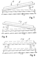
- FIG. 7 is a diagrammatic view illustrating the panel with only one side thereof at its raised position relative to the frame of the ventilating unit;
- FIG. 8 is a diagrammatic view illustrating the panel with only the other side thereof at its raised position relative to the frame of the ventilating unit;
- FIG. 9 is a diagrammatic view illustrating the panel with both sides thereof at their raised positions relative to the frame of the ventilating unit.
- FIG. 10 is a schematic view of the electrical control system for the drive motors of the present invention.
- FIG. 1 illustrates a selectively openable ventilation device 10 which includes a frame 12 mounted in a wall 14 of a vehicle, such as a school bus, van, or the like, and a movable panel member 16 .
- the frame 12 is generally rectangular with the middle portion thereof forming a ventilation opening 12 ′
- the panel 16 has a configuration corresponding generally to the ventilation opening 12 ′ so that when the panel member 16 is in its closed position abutting the frame 12 , as illustrated in FIG. 1, the ventilation opening 12 ′ is closed, and when the panel 16 is disposed in a raised position above the frame 12 , as will be explained in greater detail presently, the ventilation opening 12 ′ is open to permit ventilating air to pass into and/or out of the vehicle.
- FIG. 2 The mechanism for moving the panel 16 between its open and closed positions is illustrated in FIG. 2, and this mechanism includes two identical linkage assemblies 18 , one of which is connected to one side edge of the panel 16 and the other of which is attached to the opposite side edge of the panel 16 for a purpose to be described presently. Since the two linkage assemblies 18 are identical, like reference numerals have been used to identify the corresponding elements in each of the linkage assemblies 18 .
- Each linkage assembly 18 includes a conventional drive motor 20 having one of its ends pivotally connected to the frame 12 by pivot bracket 22 .
- the drive motor 20 may be any type of well known reversible motors, such as a hydraulic motor, pneumatic motor or the like. However, in the preferred embodiment of the present invention, the drive motor 20 is a reversible electric motor, such as a Model LA12-2 motor manufactured by Linak A-S, located in Denmark.
- the drive motor 20 includes a drive rod 24 that is moved in a longitudinal path into and out of the confines of the drive motor 20 .
- the extending end of the drive rod 24 has a crossbar 26 mounted therein to extend perpendicularly with respect to the axis of the drive rod 24 .
- Each of the linkage assemblies 18 also includes a pair of brackets 28 mounted within the confines of the panel 16 and formed with downwardly directed slots 30 , and the opposite end portions of the crossbar 26 extend through the slots 30 for movement therein.
- a pair of operating links 32 are each connected at one of its ends to the opposite ends, respectively, of the crossbar 26 by a lost motion slot 34 , and the other end of each of the operating links 32 is pivotally mounted to one side of the frame 12 by pivot bracket 36 .
- a latching assembly 38 is provided for each of the operating links 32 , and these latching assemblies 38 include a latching member 40 that is mounted for sliding movement on a linkage bracket 28 by slide pin 42 secured to the linkage bracket 28 and extending outwardly through a slot 44 in the latching member 40 .
- a coil spring 46 is secured at one of its ends to the linkage bracket 28 , and at its other end to one end of the latching member 40 , the coil spring 46 being arranged to normally bias the latching member 40 in a direction outwardly from the linkage bracket 28 .
- the outermost end of the latching member 40 is formed with a hook-shaped surface portion 48 , and the adjacent end of the operating link 32 is provided with a pin element 50 extending outwardly therefrom, all for a purpose to be explained in greater detail below.
- each of the operating links 32 is formed with a projection 52 extending outwardly therefrom, and the adjacent linkage bracket 28 is provided with a flange element 54 that is positioned to be engaged by the projection 52 when the operating link 32 is at its fully-extended or raised position.
- linkage assemblies 18 The operation of the linkage assemblies 18 is best illustrated in FIGS. 3-6, and while only one linkage assembly 18 is illustrated in these drawings, it will be understood that the other linkage assembly 18 operates in exactly the same manner.
- FIG. 3 illustrates the linkage assembly 18 at its position where the panel 16 is in abutment with the frame 12 to close the ventilation opening 12 ′ therein. It will be noted that the drive rod 24 of the drive motor 20 is in its retracted position, and the extending ends of the crossbar 26 are disposed in the innermost and uppermost portion of the slots 30 in the linkage brackets 28 .
- the ends of the crossbar 26 extend through the slots 30 to engage an upstanding flange portion 56 of the latching members 40 so that the latching members 40 are positioned at their retracted position relative to the linkage brackets 28 , and the springs 46 serve to retract the hook-shaped surface 48 in the opening mode to positively urge the hook-shaped surface 48 of the latching members 40 against the pin elements 50 whereby the hook-shaped surface portions act as a cam surface to urge, under the influence of the crossbar 26 , the pin elements 50 and the attached operating links 32 in a downward direction to cause the side edge of the panel 16 to be securely pressed into closing contact with the frame 12 and assist in causing the ventilation opening 12 ′ to be properly sealed.
- the appropriate one of the electric drive motors 20 is energized and causes the drive rod 24 to move outwardly from the drive motor 20 .
- the initial outward movement of the drive rod 24 causes the crossbar 26 to move downwardly in the slots 30 in the linkage brackets 28 , and, as a result, the coil springs 46 will cause the latching members 40 to move outwardly relative to the linkage brackets 28 until the hooked-shaped surface portion 48 clears the pin elements 50 to thereby release the operating links 32 .
- the electrical control circuit for operating the electrical drive motors 20 is schematically illustrated in FIG. 10 .
- the two drive motors 20 are mounted in the panel 16 , which is indicated by dotted lines in FIG. 10 .
- a pair of conventional double pole, double throw electrical switches 58 are mounted within the vehicle, preferably somewhere that is convenient to the operator of the vehicle, such as on the dash 62 which is indicated in dotted line in FIG. 10 .
- the two switches 58 are independently operated to permit the two drive motors to be controlled independently.
- a switch element 60 is in the full line position as shown in FIG.
- FIGS. 7-9 The overall operation of the present invention is diagrammatically illustrated in FIGS. 7-9.
- the ventilation unit 10 is disposed in the top wall of the vehicle, and one of the side edges of the panel 16 which is raised and lowered by a linkage assembly 18 is positioned to face forwardly of the vehicle while the other side edge of the panel 16 operated by a linkage assembly 18 faces rearwardly of the vehicle.
- the operator of the vehicle has a number of options in selecting a desired ventilation flow path, and each option is quickly and easily available to the operator.
- the right hand end of the ventilation unit 10 is facing forwardly of the vehicle to which it is attached, and if the operator wants to only admit outside ventilating air into the vehicle, the drive motor 20 of the linkage assembly 18 attached to the front side edge of the panel 16 is operated, and the front edge of the panel 16 is thereby raised relative to the frame 12 in the manner described above, whereupon the ventilation opening 12 ′ in the frame 12 is opened at the front edge thereof as illustrated in FIG. 7 so that ventilating air can pass into and out of the vehicle through the ventilation opening 12 ′.
- the disposition of the panel 16 as illustrated in FIG. 7, combined with the forward motion of the vehicle will combine to cause outside ventilating air to be forced into the vehicle through the ventilation opening 12 ′.
- the operator may also elect to energize the drive motor 20 of the linkage assembly 18 attached to the rear side edge of the panel 16 , whereupon only the rear side edge of the panel 16 is disposed in the raised position. If the vehicle is moving in a forward direction, the air flow over and around the ventilation unit 10 will tend to create a vacuum that will withdraw air from the inside of the vehicle and thereby set up a flow of ventilating air into the vehicle through conventional ventilating ducts in the vehicle itself and outwardly through the ventilating unit 10 .
- the operator can also raise both the front and rear side edges of the panel 16 as illustrated in FIG. 9, whereupon maximum ventilation is obtained around the entire periphery of the ventilation opening 12 ′ in the frame 12 .
- the independent operation of the two drive motors 20 and the linkage assemblies 18 provide the operator of the vehicle with a variety of options in obtaining a desired flow pattern of ventilating air through the vehicle, and the panel 16 can be quickly and easily raised at either or both side edges thereof by operating either or both of the switches 58 , and it is not necessary to go through an entire sequence of movements to obtain the desired position of the panel 16 as is the case with the known ventilation units discussed above.
Abstract
Description
Claims (6)
Priority Applications (2)
| Application Number | Priority Date | Filing Date | Title |
|---|---|---|---|
| US09/511,125 US6347484B1 (en) | 2000-02-22 | 2000-02-22 | Ventilation unit for vehicles |
| CA002335431A CA2335431C (en) | 2000-02-22 | 2001-02-12 | Ventilation unit for vehicles |
Applications Claiming Priority (1)
| Application Number | Priority Date | Filing Date | Title |
|---|---|---|---|
| US09/511,125 US6347484B1 (en) | 2000-02-22 | 2000-02-22 | Ventilation unit for vehicles |
Publications (1)
| Publication Number | Publication Date |
|---|---|
| US6347484B1 true US6347484B1 (en) | 2002-02-19 |
Family
ID=24033544
Family Applications (1)
| Application Number | Title | Priority Date | Filing Date |
|---|---|---|---|
| US09/511,125 Expired - Lifetime US6347484B1 (en) | 2000-02-22 | 2000-02-22 | Ventilation unit for vehicles |
Country Status (2)
| Country | Link |
|---|---|
| US (1) | US6347484B1 (en) |
| CA (1) | CA2335431C (en) |
Cited By (24)
| Publication number | Priority date | Publication date | Assignee | Title |
|---|---|---|---|---|
| US6572182B2 (en) | 2001-04-18 | 2003-06-03 | Transpec, Inc. | Motorized vent and escape hatch assembly |
| US20050224635A1 (en) * | 2003-07-22 | 2005-10-13 | Hein Jeffrey M | Dual action inlet door and method for use thereof |
| WO2005108727A1 (en) * | 2004-05-06 | 2005-11-17 | L.A.M. S.R.L. | A device for movement of aperture closing elements for vehicles, in particular vehicles for transport of people, and a closure device provided with the movement device |
| US20060230694A1 (en) * | 2005-04-18 | 2006-10-19 | Rubbermaid, Inc. | Roof panel assembly with skylight |
| US20090313920A1 (en) * | 2005-04-27 | 2009-12-24 | Serge Jaure | Type of shutter |
| ITBO20120431A1 (en) * | 2012-08-03 | 2014-02-04 | Scalabros S R L | ROOF RACK FOR VEHICLES |
| ITBO20120432A1 (en) * | 2012-08-03 | 2014-02-04 | Scalabros S R L | ROOF RACK FOR VEHICLES |
| EP2692562A1 (en) * | 2012-08-03 | 2014-02-05 | Scalabros S.r.l. | Roof hatch for vehicles |
| WO2015191029A1 (en) * | 2014-06-09 | 2015-12-17 | Atwood Mobile Products, Inc. | Shrouded roof vent for a vehicle |
| CN106256584A (en) * | 2015-06-17 | 2016-12-28 | 凯斯纽荷兰(中国)管理有限公司 | The system and method for the air stream in the enging cabin regulating off-road vehicle |
| US9551499B1 (en) * | 2006-10-20 | 2017-01-24 | Omni Containment Systems, Llc | Hinge assembly for supporting a fan on a roof |
| USD782941S1 (en) | 2014-06-09 | 2017-04-04 | Dometic Sweden Ab | Vent housing |
| USD806223S1 (en) | 2015-07-01 | 2017-12-26 | Dometic Sweden Ab | Fan |
| CN108382173A (en) * | 2018-02-09 | 2018-08-10 | 浙江工贸职业技术学院 | Skylight is automatically closed in a kind of automobile rainy day |
| US20180258677A1 (en) * | 2017-03-10 | 2018-09-13 | Bad Bass Industries, LLC | Hinge Allowing Opening Along More Than One Axis and Complete Disengagement of Hinge and Removal of Hinged Device |
| US10093152B2 (en) | 2014-06-09 | 2018-10-09 | Dometic Sweden Ab | Shrouded roof vent for a vehicle |
| USD832987S1 (en) | 2016-10-13 | 2018-11-06 | Dometic Sweden Ab | Roof fan shroud |
| US10400783B1 (en) | 2015-07-01 | 2019-09-03 | Dometic Sweden Ab | Compact fan for a recreational vehicle |
| US20190283682A1 (en) * | 2018-03-13 | 2019-09-19 | Ford Global Technologies, Llc | Roof accessory interface |
| US10960744B1 (en) * | 2018-11-19 | 2021-03-30 | Zoox, Inc. | Multi-directional vehicle roof cover system |
| US11027595B2 (en) | 2016-10-13 | 2021-06-08 | Dometic Sweden Ab | Roof fan assembly |
| US11203302B2 (en) * | 2018-06-13 | 2021-12-21 | Thule Sweden Ab | Vehicle carrier box |
| US20230116011A1 (en) * | 2021-10-12 | 2023-04-13 | Caterpillar Inc. | Secondary control system and method for mounting with service orientation |
| US11697324B2 (en) | 2019-05-21 | 2023-07-11 | Hyundai Motor Company | Roof vent |
Citations (11)
| Publication number | Priority date | Publication date | Assignee | Title |
|---|---|---|---|---|
| US2374618A (en) * | 1943-07-10 | 1945-04-24 | Perreton Arnold | Window sash support |
| US4412404A (en) * | 1982-04-19 | 1983-11-01 | Transpec, Inc. | Combined vent and escape hatch |
| US4420184A (en) * | 1981-12-04 | 1983-12-13 | American Sunroof Corporation | Pivotal-sliding roof panel apparatus |
| US4449325A (en) * | 1982-06-29 | 1984-05-22 | Consort Aluminium Limited | Adjustable window assembly |
| US4624076A (en) * | 1984-06-18 | 1986-11-25 | Schoeman Johannes F | Door opener |
| US4630029A (en) * | 1985-01-22 | 1986-12-16 | Walter Hayward | Display systems |
| US4866882A (en) * | 1988-04-29 | 1989-09-19 | Cappello Emanuel J | Stand-out window opening mechanism |
| US4929019A (en) * | 1988-01-19 | 1990-05-29 | Oy Parton Ab | Device for opening and closing the roof hatch of a vehicle |
| US5546705A (en) * | 1993-10-02 | 1996-08-20 | Huwil-Werke Gmbh | Support for holding a closing element |
| US5675940A (en) * | 1996-10-15 | 1997-10-14 | Bahar; Reuben | Skylight leakage barrier |
| US6070637A (en) * | 1997-07-31 | 2000-06-06 | Jancan; Marty | Horizontally openable window |
-
2000
- 2000-02-22 US US09/511,125 patent/US6347484B1/en not_active Expired - Lifetime
-
2001
- 2001-02-12 CA CA002335431A patent/CA2335431C/en not_active Expired - Fee Related
Patent Citations (11)
| Publication number | Priority date | Publication date | Assignee | Title |
|---|---|---|---|---|
| US2374618A (en) * | 1943-07-10 | 1945-04-24 | Perreton Arnold | Window sash support |
| US4420184A (en) * | 1981-12-04 | 1983-12-13 | American Sunroof Corporation | Pivotal-sliding roof panel apparatus |
| US4412404A (en) * | 1982-04-19 | 1983-11-01 | Transpec, Inc. | Combined vent and escape hatch |
| US4449325A (en) * | 1982-06-29 | 1984-05-22 | Consort Aluminium Limited | Adjustable window assembly |
| US4624076A (en) * | 1984-06-18 | 1986-11-25 | Schoeman Johannes F | Door opener |
| US4630029A (en) * | 1985-01-22 | 1986-12-16 | Walter Hayward | Display systems |
| US4929019A (en) * | 1988-01-19 | 1990-05-29 | Oy Parton Ab | Device for opening and closing the roof hatch of a vehicle |
| US4866882A (en) * | 1988-04-29 | 1989-09-19 | Cappello Emanuel J | Stand-out window opening mechanism |
| US5546705A (en) * | 1993-10-02 | 1996-08-20 | Huwil-Werke Gmbh | Support for holding a closing element |
| US5675940A (en) * | 1996-10-15 | 1997-10-14 | Bahar; Reuben | Skylight leakage barrier |
| US6070637A (en) * | 1997-07-31 | 2000-06-06 | Jancan; Marty | Horizontally openable window |
Cited By (32)
| Publication number | Priority date | Publication date | Assignee | Title |
|---|---|---|---|---|
| EP1457375A1 (en) * | 2001-04-18 | 2004-09-15 | Transpec, Inc. | Motorized vent and escape hatch assembly |
| US6572182B2 (en) | 2001-04-18 | 2003-06-03 | Transpec, Inc. | Motorized vent and escape hatch assembly |
| US20050224635A1 (en) * | 2003-07-22 | 2005-10-13 | Hein Jeffrey M | Dual action inlet door and method for use thereof |
| US7014144B2 (en) * | 2003-07-22 | 2006-03-21 | Honeywell International, Inc. | Dual action inlet door and method for use thereof |
| WO2005108727A1 (en) * | 2004-05-06 | 2005-11-17 | L.A.M. S.R.L. | A device for movement of aperture closing elements for vehicles, in particular vehicles for transport of people, and a closure device provided with the movement device |
| US20060230694A1 (en) * | 2005-04-18 | 2006-10-19 | Rubbermaid, Inc. | Roof panel assembly with skylight |
| US7721493B2 (en) | 2005-04-18 | 2010-05-25 | Rubbermaid Incorporated | Roof panel assembly with skylight |
| US20090313920A1 (en) * | 2005-04-27 | 2009-12-24 | Serge Jaure | Type of shutter |
| US9551499B1 (en) * | 2006-10-20 | 2017-01-24 | Omni Containment Systems, Llc | Hinge assembly for supporting a fan on a roof |
| ITBO20120431A1 (en) * | 2012-08-03 | 2014-02-04 | Scalabros S R L | ROOF RACK FOR VEHICLES |
| ITBO20120432A1 (en) * | 2012-08-03 | 2014-02-04 | Scalabros S R L | ROOF RACK FOR VEHICLES |
| EP2692562A1 (en) * | 2012-08-03 | 2014-02-05 | Scalabros S.r.l. | Roof hatch for vehicles |
| USD782940S1 (en) | 2014-06-09 | 2017-04-04 | Dometic Sweden Ab | Vent housing |
| USD782941S1 (en) | 2014-06-09 | 2017-04-04 | Dometic Sweden Ab | Vent housing |
| USD782939S1 (en) | 2014-06-09 | 2017-04-04 | Dometic Sweden Ab | Vent housing |
| WO2015191029A1 (en) * | 2014-06-09 | 2015-12-17 | Atwood Mobile Products, Inc. | Shrouded roof vent for a vehicle |
| US10093152B2 (en) | 2014-06-09 | 2018-10-09 | Dometic Sweden Ab | Shrouded roof vent for a vehicle |
| US10059192B2 (en) * | 2015-06-17 | 2018-08-28 | Cnh Industrial America Llc | System and method for adjusting air flow in an engine compartment of an off-road vehicle |
| CN106256584A (en) * | 2015-06-17 | 2016-12-28 | 凯斯纽荷兰(中国)管理有限公司 | The system and method for the air stream in the enging cabin regulating off-road vehicle |
| USD806223S1 (en) | 2015-07-01 | 2017-12-26 | Dometic Sweden Ab | Fan |
| US10400783B1 (en) | 2015-07-01 | 2019-09-03 | Dometic Sweden Ab | Compact fan for a recreational vehicle |
| USD832987S1 (en) | 2016-10-13 | 2018-11-06 | Dometic Sweden Ab | Roof fan shroud |
| USD841139S1 (en) | 2016-10-13 | 2019-02-19 | Dometic Sweden Ab | Roof fan shroud |
| US11027595B2 (en) | 2016-10-13 | 2021-06-08 | Dometic Sweden Ab | Roof fan assembly |
| US20180258677A1 (en) * | 2017-03-10 | 2018-09-13 | Bad Bass Industries, LLC | Hinge Allowing Opening Along More Than One Axis and Complete Disengagement of Hinge and Removal of Hinged Device |
| CN108382173A (en) * | 2018-02-09 | 2018-08-10 | 浙江工贸职业技术学院 | Skylight is automatically closed in a kind of automobile rainy day |
| US20190283682A1 (en) * | 2018-03-13 | 2019-09-19 | Ford Global Technologies, Llc | Roof accessory interface |
| US10787131B2 (en) * | 2018-03-13 | 2020-09-29 | Ford Global Technologies, Llc | Roof accessory interface |
| US11203302B2 (en) * | 2018-06-13 | 2021-12-21 | Thule Sweden Ab | Vehicle carrier box |
| US10960744B1 (en) * | 2018-11-19 | 2021-03-30 | Zoox, Inc. | Multi-directional vehicle roof cover system |
| US11697324B2 (en) | 2019-05-21 | 2023-07-11 | Hyundai Motor Company | Roof vent |
| US20230116011A1 (en) * | 2021-10-12 | 2023-04-13 | Caterpillar Inc. | Secondary control system and method for mounting with service orientation |
Also Published As
| Publication number | Publication date |
|---|---|
| CA2335431A1 (en) | 2001-08-22 |
| CA2335431C (en) | 2003-08-26 |
Similar Documents
| Publication | Publication Date | Title |
|---|---|---|
| US6347484B1 (en) | Ventilation unit for vehicles | |
| US2836457A (en) | Let-down type vehicle closure | |
| EP1628845B1 (en) | Collapsible air vent closure | |
| US6669278B2 (en) | Automotive vehicle roof system having multiple sunroofs | |
| KR101662547B1 (en) | Dual open panorama-sunroof | |
| JPH0769070A (en) | Multiple location retractable roof of car | |
| JP2001180282A (en) | Sunroof | |
| US7434873B2 (en) | Pop top trailer | |
| JPH02290719A (en) | Sliding roof device for vehicle | |
| EP0325380B1 (en) | A device for opening and closing the roof hatch of a vehicle | |
| JPH10140886A (en) | Expandable door handle | |
| WO2020109984A1 (en) | Convertible car | |
| JP2012086647A (en) | Automobile with cowl louver and cowl panel | |
| JP3546674B2 (en) | Power window control device | |
| US2070113A (en) | Motor vehicle | |
| JP4796968B2 (en) | Roof opening system for automobile | |
| US6412858B2 (en) | Motor vehicle roof with ventilator means | |
| CN114379339A (en) | Vehicle with a steering wheel | |
| US2667113A (en) | Ventilation system for vehicle bodies | |
| EP0409295A1 (en) | Sliding roof for a vehicle | |
| KR19990023913U (en) | Vehicle air vent cover device | |
| JP2002160517A (en) | Ventilator for vehicles | |
| JPH0339845B2 (en) | ||
| KR100994912B1 (en) | Air Conditioning Apparatus for a Car Seat | |
| JP2643071B2 (en) | Sunroof equipment for automobiles |
Legal Events
| Date | Code | Title | Description |
|---|---|---|---|
| AS | Assignment |
Owner name: SPECIALTY MANUFACTURING CO., INC., NORTH CAROLINA Free format text: ASSIGNMENT OF ASSIGNORS INTEREST;ASSIGNOR:SWANGER, ERIC D.;REEL/FRAME:010633/0482 Effective date: 20000202 |
|
| STCF | Information on status: patent grant |
Free format text: PATENTED CASE |
|
| FPAY | Fee payment |
Year of fee payment: 4 |
|
| AS | Assignment |
Owner name: THE ELLISON COMPANY, NORTH CAROLINA Free format text: CONFIRMATORY ASSIGNMENT;ASSIGNOR:SWANGER, ERIC D.;REEL/FRAME:017833/0658 Effective date: 20060623 |
|
| AS | Assignment |
Owner name: THE ELLISON COMPANY, INC., NORTH CAROLINA Free format text: CORRECTIVE ASSIGNMENT TO CORRECT THE ASSIGNEE NAME, CHANGING THE ELLISON COMPANY TO THE ELLISON COMPANY, INC. PREVIOUSLY RECORDED ON REEL 017833 FRAME 0658;ASSIGNOR:SWANGER, ERIC D.;REEL/FRAME:017858/0568 Effective date: 20060623 |
|
| AS | Assignment |
Owner name: SPECIALTY MANUFACTURING, INC., CALIFORNIA Free format text: ASSIGNMENT OF ASSIGNORS INTEREST;ASSIGNOR:ELLISON COMPANY, INC., THE;REEL/FRAME:018087/0466 Effective date: 20060627 |
|
| AS | Assignment |
Owner name: MERRILL LYNCH CAPITAL, A DIVISION OF MERRILL LYNCH Free format text: SECURITY AGREEMENT;ASSIGNOR:SPECIALTY MANUFACTURING, INC.;REEL/FRAME:017971/0357 Effective date: 20060627 |
|
| FPAY | Fee payment |
Year of fee payment: 8 |
|
| FPAY | Fee payment |
Year of fee payment: 12 |
|
| AS | Assignment |
Owner name: SPECIALTY MANUFACTURING INC., NORTH CAROLINA Free format text: PATENT RELEASE AND REASSIGNMENT OF REEL/FRAME NO. 017971/0357;ASSIGNOR:GE BUSINESS FINANCIAL SERVICES INC. (FORMERLY KNOWN AS MERRILL LYNCH CAPITAL, A DIVISION OF MERRILL LYNCH BUSINESS FINANCIAL SERVICES, INC.);REEL/FRAME:031343/0617 Effective date: 20130930 |
|
| AS | Assignment |
Owner name: BNP PARIBAS, AS ADMINISTRATIVE AGENT, NEW YORK Free format text: GRANT OF PATENT SECURITY INTEREST;ASSIGNOR:SPECIALTY MANUFACTURING, INC.;REEL/FRAME:031396/0189 Effective date: 20130930 |
|
| AS | Assignment |
Owner name: OCM FIE, LLC, AS ADMINISTRATIVE AGENT, NEW YORK Free format text: GRANT OF SECOND LIEN PATENT SECURITY AGREEMENT;ASSIGNOR:SPECIALTY MANUFACTURING, INC.;REEL/FRAME:031413/0738 Effective date: 20130930 |
|
| AS | Assignment |
Owner name: RANDALL MANUFACTURING LLC, MISSOURI Free format text: RELEASE BY SECURED PARTY;ASSIGNOR:BNP PARIBAS;REEL/FRAME:045234/0663 Effective date: 20180201 Owner name: SPECIALTY MANUFACTURING, INC., MISSOURI Free format text: RELEASE BY SECURED PARTY;ASSIGNOR:BNP PARIBAS;REEL/FRAME:045234/0663 Effective date: 20180201 Owner name: REAR VIEW SAFETY INC., MISSOURI Free format text: RELEASE BY SECURED PARTY;ASSIGNOR:OCM FIE, LLC;REEL/FRAME:045234/0627 Effective date: 20180201 Owner name: REAR VIEW SAFETY INC., MISSOURI Free format text: RELEASE BY SECURED PARTY;ASSIGNOR:BNP PARIBAS;REEL/FRAME:045234/0663 Effective date: 20180201 Owner name: IEM, INC., MISSOURI Free format text: RELEASE BY SECURED PARTY;ASSIGNOR:BNP PARIBAS;REEL/FRAME:045234/0663 Effective date: 20180201 Owner name: ROM ACQUISITION CORPORATION, MISSOURI Free format text: RELEASE BY SECURED PARTY;ASSIGNOR:OCM FIE, LLC;REEL/FRAME:045234/0627 Effective date: 20180201 Owner name: ELKHART BRASS MANUFACTURING COMPANY, INC., MISSOUR Free format text: RELEASE BY SECURED PARTY;ASSIGNOR:BNP PARIBAS;REEL/FRAME:045234/0663 Effective date: 20180201 Owner name: ROM ACQUISITION CORPORATION, MISSOURI Free format text: RELEASE BY SECURED PARTY;ASSIGNOR:BNP PARIBAS;REEL/FRAME:045234/0663 Effective date: 20180201 Owner name: RANDALL MANUFACTURING LLC, MISSOURI Free format text: RELEASE BY SECURED PARTY;ASSIGNOR:OCM FIE, LLC;REEL/FRAME:045234/0627 Effective date: 20180201 Owner name: SPECIALTY MANUFACTURING, INC., MISSOURI Free format text: RELEASE BY SECURED PARTY;ASSIGNOR:OCM FIE, LLC;REEL/FRAME:045234/0627 Effective date: 20180201 Owner name: FIRE RESEARCH CORP., MISSOURI Free format text: RELEASE BY SECURED PARTY;ASSIGNOR:OCM FIE, LLC;REEL/FRAME:045234/0627 Effective date: 20180201 Owner name: IEM, INC., MISSOURI Free format text: RELEASE BY SECURED PARTY;ASSIGNOR:OCM FIE, LLC;REEL/FRAME:045234/0627 Effective date: 20180201 Owner name: FIRE RESEARCH CORP., MISSOURI Free format text: RELEASE BY SECURED PARTY;ASSIGNOR:BNP PARIBAS;REEL/FRAME:045234/0663 Effective date: 20180201 Owner name: ELKHART BRASS MANUFACTURING COMPANY, INC., MISSOUR Free format text: RELEASE BY SECURED PARTY;ASSIGNOR:OCM FIE, LLC;REEL/FRAME:045234/0627 Effective date: 20180201 |
|
| AS | Assignment |
Owner name: GOLDMAN SACHS BANK USA, AS COLLATERAL AGENT, NEW Y Free format text: SECURITY INTEREST;ASSIGNOR:SPECIALTY MANUFACTURING, INC.;REEL/FRAME:044953/0187 Effective date: 20180201 Owner name: UBS AG, STAMFORD BRANCH, AS COLLATERAL AGENT, CONN Free format text: SECURITY INTEREST;ASSIGNOR:SPECIALTY MANUFACTURING, INC.;REEL/FRAME:044953/0231 Effective date: 20180201 |
|
| AS | Assignment |
Owner name: SPECIALTY MANUFACTURING, INC., CALIFORNIA Free format text: RELEASE OF FIRST LIEN SECURITY INTEREST IN PATENTS (RELEASES RF 044953/0187);ASSIGNOR:GOLDMAN SACHS BANK USA, AS COLLATERAL AGENT;REEL/FRAME:066613/0288 Effective date: 20240213 |
|
| AS | Assignment |
Owner name: SPECIALTY MANUFACTURING, INC., CALIFORNIA Free format text: RELEASE OF SECOND LIEN SECURITY INTEREST IN PATENTS (RELEASES RF 044953/0231);ASSIGNOR:UBS AG, STAMFORD BRANCH, AS COLLATERAL AGENT;REEL/FRAME:066624/0229 Effective date: 20240213 |