US6341675B1 - Tube-pressed brake - Google Patents
Tube-pressed brake Download PDFInfo
- Publication number
- US6341675B1 US6341675B1 US09/406,846 US40684699A US6341675B1 US 6341675 B1 US6341675 B1 US 6341675B1 US 40684699 A US40684699 A US 40684699A US 6341675 B1 US6341675 B1 US 6341675B1
- Authority
- US
- United States
- Prior art keywords
- tube
- pressure fluid
- pressure
- circuit
- pressure control
- Prior art date
- Legal status (The legal status is an assumption and is not a legal conclusion. Google has not performed a legal analysis and makes no representation as to the accuracy of the status listed.)
- Expired - Lifetime
Links
Images


Classifications
-
- F—MECHANICAL ENGINEERING; LIGHTING; HEATING; WEAPONS; BLASTING
- F16—ENGINEERING ELEMENTS AND UNITS; GENERAL MEASURES FOR PRODUCING AND MAINTAINING EFFECTIVE FUNCTIONING OF MACHINES OR INSTALLATIONS; THERMAL INSULATION IN GENERAL
- F16D—COUPLINGS FOR TRANSMITTING ROTATION; CLUTCHES; BRAKES
- F16D49/00—Brakes with a braking member co-operating with the periphery of a drum, wheel-rim, or the like
- F16D49/14—Brakes with a braking member co-operating with the periphery of a drum, wheel-rim, or the like shaped as a fluid-filled flexible member actuated by variation of the fluid pressure
-
- B—PERFORMING OPERATIONS; TRANSPORTING
- B60—VEHICLES IN GENERAL
- B60T—VEHICLE BRAKE CONTROL SYSTEMS OR PARTS THEREOF; BRAKE CONTROL SYSTEMS OR PARTS THEREOF, IN GENERAL; ARRANGEMENT OF BRAKING ELEMENTS ON VEHICLES IN GENERAL; PORTABLE DEVICES FOR PREVENTING UNWANTED MOVEMENT OF VEHICLES; VEHICLE MODIFICATIONS TO FACILITATE COOLING OF BRAKES
- B60T1/00—Arrangements of braking elements, i.e. of those parts where braking effect occurs specially for vehicles
- B60T1/02—Arrangements of braking elements, i.e. of those parts where braking effect occurs specially for vehicles acting by retarding wheels
- B60T1/06—Arrangements of braking elements, i.e. of those parts where braking effect occurs specially for vehicles acting by retarding wheels acting otherwise than on tread, e.g. employing rim, drum, disc, or transmission or on double wheels
- B60T1/067—Arrangements of braking elements, i.e. of those parts where braking effect occurs specially for vehicles acting by retarding wheels acting otherwise than on tread, e.g. employing rim, drum, disc, or transmission or on double wheels employing drum
-
- B—PERFORMING OPERATIONS; TRANSPORTING
- B60—VEHICLES IN GENERAL
- B60T—VEHICLE BRAKE CONTROL SYSTEMS OR PARTS THEREOF; BRAKE CONTROL SYSTEMS OR PARTS THEREOF, IN GENERAL; ARRANGEMENT OF BRAKING ELEMENTS ON VEHICLES IN GENERAL; PORTABLE DEVICES FOR PREVENTING UNWANTED MOVEMENT OF VEHICLES; VEHICLE MODIFICATIONS TO FACILITATE COOLING OF BRAKES
- B60T13/00—Transmitting braking action from initiating means to ultimate brake actuator with power assistance or drive; Brake systems incorporating such transmitting means, e.g. air-pressure brake systems
- B60T13/10—Transmitting braking action from initiating means to ultimate brake actuator with power assistance or drive; Brake systems incorporating such transmitting means, e.g. air-pressure brake systems with fluid assistance, drive, or release
- B60T13/12—Transmitting braking action from initiating means to ultimate brake actuator with power assistance or drive; Brake systems incorporating such transmitting means, e.g. air-pressure brake systems with fluid assistance, drive, or release the fluid being liquid
-
- F—MECHANICAL ENGINEERING; LIGHTING; HEATING; WEAPONS; BLASTING
- F16—ENGINEERING ELEMENTS AND UNITS; GENERAL MEASURES FOR PRODUCING AND MAINTAINING EFFECTIVE FUNCTIONING OF MACHINES OR INSTALLATIONS; THERMAL INSULATION IN GENERAL
- F16D—COUPLINGS FOR TRANSMITTING ROTATION; CLUTCHES; BRAKES
- F16D65/00—Parts or details
- F16D65/78—Features relating to cooling
- F16D2065/782—Features relating to cooling the brake-actuating fluid being used as a coolant
Definitions
- This invention relates to a tube-pressed brake suitable for use in a clutch, a brake or the like.
- Conventional tube-pressed brakes are each constructed of an outer frame, a tube arranged inside the outer frame, and a counterpart arranged inside the tube and rotatable relative to the tube.
- a pressure fluid is injected into the tube upon transmission of a torque, and is discharged upon allowing the brake to idle.
- FIG. 5 is a cross-sectional view showing a conventional tube-pressed brake as viewed from a front
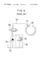
- FIG. 6 is a diagram illustrating an example of a fluid pressure circuit for the conventional tube-pressed brake.
- an outer frame 20 a pressure fluid supply hole 21 , and a tube 30 are depicted.
- the tube 30 is folded back along opposite ends of the outer frame 20 , between which a cut-off portion 23 is formed.
- the tube 30 is sealed and fixed at folded portions 31 thereof on the outer frame 20 by presser plates 40 and rivets 41 , respectively.
- Designated at numeral 32 are springs inserted within the tube 30 . These springs 32 urge the tube 30 outwardly such that, during idling with the pressure fluid discharged from the tube 30 , the tube 30 is prevented from contacting a brake drum (not shown) arranged inside the tube 30 .
- the pressure fluid is delivered by a pump 52 from a reservoir 53 to the pressure fluid supply hole 21 of the tube 30 via a solenoid-operated valve 60 through a line 50 .
- Numeral 55 indicates a pressure control circuit which includes a relief valve 54 .
- the pressure fluid is delivered to the tube 30 via the solenoid-operated valve 60 .
- the solenoid-operated valve 60 is changed over (into the position depicted in FIG. 6) such that the pressure fluid flows in an opposite direction through the line 50 and returns to the reservoir 53 .
- a tube-pressed brake of the above-described conventional construction is unable to release heat produced during transmission of a torque, so that a friction surface of a tube and a counterpart, such as a drum, become hot. This leads to the occurrence of a problem in durability and also to the development of an inconvenience that the heat resistance has to be heightened.
- the present invention provides a tube-pressed brake having a tube, said tube being inflatable by injection of a pressure fluid thereinto such that a torque can be transmitted to a counterpart, comprising a pressure fluid circuit for circulating said pressure fluid through an interior of said tube.
- the pressure fluid is allowed to circulate through the interior of the tube of the tube-pressed brake. This has made it possible to release heat, which is produced during transmission of a torque, to the outside of the brake. As a consequence, it has become possible to improve the durability of the tube and its counterpart, such as a drum, and hence to prolong their service life.
- FIG. 1 is a cross-sectional view of a tube-pressed brake according to an embodiment of the present invention as viewed from a front;
- FIG. 2 is a cross-sectional view of the tube-pressed brake taken along line II-O;
- FIG. 3 is a cross-sectional view of the tube-pressed brake taken along line III-O;
- FIG. 4 is a diagram showing a fluid circuit for the tube-pressed brake according to the embodiment of the present invention.
- FIG. 5 is a cross-sectional view of a conventional tube-pressed brake as viewed from a front
- FIG. 6 is a diagram illustrating an example of a fluid circuit for the conventional tube-pressed brake.
- FIGS. 1 through 4 With reference to the FIGS. 1 through 4, the tube-pressed brake 10 according to the embodiment of the present invention will hereinafter be described.
- an outer frame 20 there are shown an outer frame 20 , a pressure fluid supply hole 21 , a pressure fluid discharge hole 22 , a cut-off portion 23 of the outer frame 20 , a tube 30 , and folded portions 31 of the tube 30 .
- the tube 30 is folded back at the cut-off portion 23 of the outer frame 20 , and the tube 30 is fixed at folded portions 31 thereof on the outer frame 20 by presser plates 40 and rivets 41 , respectively.
- Designated at numeral 32 are springs inserted within the tube 30 . These springs 32 urge the tube 30 outwardly such that, when the pressure fluid is discharged from the tube 30 upon allowing the brake to idle, the tube 30 is prevented from slacking inward to avoid a contact between the tube 30 and a counterpart (not shown) such as a drum.
- a solenoid-operated valve 51 is arranged upstream the pressure fluid supply hole 21 of the tube 30 .
- another solenoid-operated valve 56 is also arranged downstream the pressure fluid discharge hole 22 .
- FIG. 4 also shows a pump 52 , a reservoir 53 , a pressure control circuit 55 including a relief valve 54 , and a line 50 .
- a pressure fluid circuit is formed of a main circuit and a pressure control circuit.
- the pressure fluid flows from the reservoir 53 to the pressure fluid supply hole 21 by way of the pump 52 and the solenoid-operated valve 51 , then enters the tube 30 from the pressure fluid supply hole 21 , and subsequent to circulation through an interior of the tube 30 , returns from the pressure fluid discharge hole 22 to the reservoir 53 via the solenoid-operated valve 56 .
- the pressure control circuit on the other hand, the pressure fluid flows from the reservoir 53 and further through the pump 52 , and then returns from a point, which is located between the solenoid-operated valve 51 and the pump 52 , to the reservoir 53 via the relief valve 54 .
- the pump 52 is driven by an engine or the like, whereby the fluid in the reservoir 53 is pumped up and delivered under pressure.
- the pressure of the pressure fluid so delivered under pressure is controlled to a desired constant pressure by the pressure control circuit 55 which includes the relief valve 54 .
- the solenoid-operated valve 51 as the first pressure control device, the pressure-controlled pressure fluid is allowed to reach the interior of the tube 30 through the pressure fluid supply hole 21 .
- the pressure fluid By opening the solenoid-operated valve 56 arranged as the second pressure control device downstream the pressure fluid discharged hole 22 , the pressure fluid is discharged through the pressure fluid discharge hole 22 and is allowed to return to the reservoir 53 through the line 50 .
- the solenoid-operated valves 51 , 56 By appropriately opening or closing the solenoid-operated valves 51 , 56 , the pressure fluid inflates the tube 30 such that a binding torque is transmitted to a counterpart such as a drum and at the same time, the pressure fluid is discharged through the pressure fluid discharge hole 22 in an amount equal to an amount of a fresh supply of the pressure fluid required to cool the interior of the tube 30 .
- the pressure fluid is supplied through the pressure fluid supply hole 21 at the same rate as the discharge rate of the pressure fluid.
- the pressure fluid is caused to circulate through the tube 30 .
- This makes it possible to release heat, which is produced at the friction surface or the like of the tube 30 as a result of transmission of a torque, to the outside of the brake and to appropriately cool the interior of the tube 30 .
- the durability of the brake can therefore be improved.
- the solenoid-operated valve 51 is closed and the solenoid-operated valve 56 is opened.
- the pressure fluid inside the tube 30 is hence allowed to return from the pressure fluid discharge hole 22 to the reservoir 53 via the solenoid-operated valve 56 .
- the pressure inside the tube 30 drops, thereby releasing the brake.
- the drive means for the pump 52 is not limited to the engine, and a desired drive means such as an electric motor may be used.
- the first and second pressure control devices may be operated either manually or electrically. These pressure control devices can be of any desired type, such as solenoid-operated valves of the normal closed or normal open type, solenoid-operated 2 -port valves, 3 -port proportional valves, or control valves actuated by pilot pressures or actuators.
Abstract
A tube-pressed brake has a tube, which is inflatable by injection of a pressure fluid thereinto such that a torque can be transmitted to a counterpart. The tube-pressed brake comprises a pressure fluid circuit for circulating the pressure fluid through an interior of the tube. The tube may be provided with a pressure fluid supply hole and a pressure fluid discharge hole, and the pressure fluid circuit may be provided with a first pressure control device arranged upstream the pressure fluid supply hole and also with a second pressure control valve arranged downstream the pressure fluid discharge hole. The pressure fluid circuit may comprise a main circuit and a pressure control circuit. Through the main circuit, the pressure fluid is allowed to successively flow through a reservoir, a pump, the first pressure control device, the tube, the second pressure control device and the reservoir in this order. The pressure control circuit allows the pressure fluid to flow from a point of the main circuit, the point being located between the pump and the first pressure control device, to the reservoir via a relief valve.
Description
a) Field of the Invention
This invention relates to a tube-pressed brake suitable for use in a clutch, a brake or the like.
b) Description of the Related Art
Conventional tube-pressed brakes are each constructed of an outer frame, a tube arranged inside the outer frame, and a counterpart arranged inside the tube and rotatable relative to the tube. A pressure fluid is injected into the tube upon transmission of a torque, and is discharged upon allowing the brake to idle.
FIG. 5 is a cross-sectional view showing a conventional tube-pressed brake as viewed from a front, and FIG. 6 is a diagram illustrating an example of a fluid pressure circuit for the conventional tube-pressed brake. In these drawings, an outer frame 20, a pressure fluid supply hole 21, and a tube 30 are depicted. The tube 30 is folded back along opposite ends of the outer frame 20, between which a cut-off portion 23 is formed. The tube 30 is sealed and fixed at folded portions 31 thereof on the outer frame 20 by presser plates 40 and rivets 41, respectively.
Designated at numeral 32 are springs inserted within the tube 30. These springs 32 urge the tube 30 outwardly such that, during idling with the pressure fluid discharged from the tube 30, the tube 30 is prevented from contacting a brake drum (not shown) arranged inside the tube 30.
As is understood from the circuit diagram of FIG. 6, the pressure fluid is delivered by a pump 52 from a reservoir 53 to the pressure fluid supply hole 21 of the tube 30 via a solenoid-operated valve 60 through a line 50. Numeral 55 indicates a pressure control circuit which includes a relief valve 54. Upon transmission of a torque, the pressure fluid is delivered to the tube 30 via the solenoid-operated valve 60. Upon idling, on the other hand, the solenoid-operated valve 60 is changed over (into the position depicted in FIG. 6) such that the pressure fluid flows in an opposite direction through the line 50 and returns to the reservoir 53.
There is an important demand for providing clutch elements or brake elements with improved heat resistance and durability. A tube-pressed brake of the above-described conventional construction is unable to release heat produced during transmission of a torque, so that a friction surface of a tube and a counterpart, such as a drum, become hot. This leads to the occurrence of a problem in durability and also to the development of an inconvenience that the heat resistance has to be heightened.
To meet the above-described demand, the present invention provides a tube-pressed brake having a tube, said tube being inflatable by injection of a pressure fluid thereinto such that a torque can be transmitted to a counterpart, comprising a pressure fluid circuit for circulating said pressure fluid through an interior of said tube.
According to the present invention, the pressure fluid is allowed to circulate through the interior of the tube of the tube-pressed brake. This has made it possible to release heat, which is produced during transmission of a torque, to the outside of the brake. As a consequence, it has become possible to improve the durability of the tube and its counterpart, such as a drum, and hence to prolong their service life.
FIG. 1 is a cross-sectional view of a tube-pressed brake according to an embodiment of the present invention as viewed from a front;
FIG. 2 is a cross-sectional view of the tube-pressed brake taken along line II-O;
FIG. 3 is a cross-sectional view of the tube-pressed brake taken along line III-O;
FIG. 4 is a diagram showing a fluid circuit for the tube-pressed brake according to the embodiment of the present invention;
FIG. 5 is a cross-sectional view of a conventional tube-pressed brake as viewed from a front; and
FIG. 6 is a diagram illustrating an example of a fluid circuit for the conventional tube-pressed brake.
With reference to the FIGS. 1 through 4, the tube-pressed brake 10 according to the embodiment of the present invention will hereinafter be described. In these drawings, there are shown an outer frame 20, a pressure fluid supply hole 21, a pressure fluid discharge hole 22, a cut-off portion 23 of the outer frame 20, a tube 30, and folded portions 31 of the tube 30. As is illustrated in FIG. 1, the tube 30 is folded back at the cut-off portion 23 of the outer frame 20, and the tube 30 is fixed at folded portions 31 thereof on the outer frame 20 by presser plates 40 and rivets 41, respectively.
Designated at numeral 32 are springs inserted within the tube 30. These springs 32 urge the tube 30 outwardly such that, when the pressure fluid is discharged from the tube 30 upon allowing the brake to idle, the tube 30 is prevented from slacking inward to avoid a contact between the tube 30 and a counterpart (not shown) such as a drum.
Operation of the tube-pressed brake according to the embodiment of the present invention will next be described with reference to FIG. 4. As a first pressure control device, a solenoid-operated valve 51 is arranged upstream the pressure fluid supply hole 21 of the tube 30. As a second pressure control device, another solenoid-operated valve 56 is also arranged downstream the pressure fluid discharge hole 22.
FIG. 4 also shows a pump 52, a reservoir 53, a pressure control circuit 55 including a relief valve 54, and a line 50.
A pressure fluid circuit is formed of a main circuit and a pressure control circuit. In the main circuit, the pressure fluid flows from the reservoir 53 to the pressure fluid supply hole 21 by way of the pump 52 and the solenoid-operated valve 51, then enters the tube 30 from the pressure fluid supply hole 21, and subsequent to circulation through an interior of the tube 30, returns from the pressure fluid discharge hole 22 to the reservoir 53 via the solenoid-operated valve 56. In the pressure control circuit, on the other hand, the pressure fluid flows from the reservoir 53 and further through the pump 52, and then returns from a point, which is located between the solenoid-operated valve 51 and the pump 52, to the reservoir 53 via the relief valve 54.
The pump 52 is driven by an engine or the like, whereby the fluid in the reservoir 53 is pumped up and delivered under pressure. The pressure of the pressure fluid so delivered under pressure is controlled to a desired constant pressure by the pressure control circuit 55 which includes the relief valve 54. By appropriately opening the solenoid-operated valve 51 as the first pressure control device, the pressure-controlled pressure fluid is allowed to reach the interior of the tube 30 through the pressure fluid supply hole 21.
By opening the solenoid-operated valve 56 arranged as the second pressure control device downstream the pressure fluid discharged hole 22, the pressure fluid is discharged through the pressure fluid discharge hole 22 and is allowed to return to the reservoir 53 through the line 50. By appropriately opening or closing the solenoid-operated valves 51,56, the pressure fluid inflates the tube 30 such that a binding torque is transmitted to a counterpart such as a drum and at the same time, the pressure fluid is discharged through the pressure fluid discharge hole 22 in an amount equal to an amount of a fresh supply of the pressure fluid required to cool the interior of the tube 30. As a result, the pressure fluid is supplied through the pressure fluid supply hole 21 at the same rate as the discharge rate of the pressure fluid. Accordingly, the pressure fluid is caused to circulate through the tube 30. This makes it possible to release heat, which is produced at the friction surface or the like of the tube 30 as a result of transmission of a torque, to the outside of the brake and to appropriately cool the interior of the tube 30. The durability of the brake can therefore be improved.
To release the brake, the solenoid-operated valve 51 is closed and the solenoid-operated valve 56 is opened. The pressure fluid inside the tube 30 is hence allowed to return from the pressure fluid discharge hole 22 to the reservoir 53 via the solenoid-operated valve 56. As a result, the pressure inside the tube 30 drops, thereby releasing the brake.
The drive means for the pump 52 is not limited to the engine, and a desired drive means such as an electric motor may be used. The first and second pressure control devices may be operated either manually or electrically. These pressure control devices can be of any desired type, such as solenoid-operated valves of the normal closed or normal open type, solenoid-operated 2-port valves, 3-port proportional valves, or control valves actuated by pilot pressures or actuators.
This application claims the priority of Japanese Patent Application No. HEI 10-275774 filed Sep. 29, 1998, which is incorporated herein by reference.
Claims (3)
1. A tube-pressed brake having a tube, said tube being inflatable by injection of a pressure fuid thereinto such that a torque can be transmitted to a counterpart, comprising a pressure fluid circuit for circulating said pressure fluid through an interior of said tube,
wherein said tube is provided with a pressure fluid supply hole and a pressure fluid discharge hole, said pressure fluid entering in through said pressure fluid supply hole and exiting through said pressure fluid discharge hole, and said pressure fluid circuit is provided with a first pressure control valve arranged upstream of said pressure fluid supply hole and a second pressure control valve arrange downstream of said pressure fluid discharge hole.
2. A tube-pressed brake according to claim 1 , wherein said pressure fluid can be caused to circulate through said tube at a rate sufficient to cool an interior of said tube.
3. A tube-pressed brake having a tube, said tube being inflatable by injection of a pressure fluid thereinto such that a torque can be transmitted to a counterpart, comprising a pressure fluid circuit for circulating said pressure fluid through an interior of said tube,
wherein said pressure fluid circuit comprises:
a main circuit, through which said pressure fluid is allowed to successively flow through a reservoir, a pump, a first pressure control device, said tube, a second pressure control device and said reservoir in this order; and
a pressure control circuit for allowing said pressure fluid to flow from a point of said main circuit, said point being located between said pump and said first pressure control device, to said reservoir via a relief valve.
Applications Claiming Priority (2)
| Application Number | Priority Date | Filing Date | Title |
|---|---|---|---|
| JP10-275774 | 1998-09-29 | ||
| JP10275774A JP2000104762A (en) | 1998-09-29 | 1998-09-29 | Tube pressurizing type brake |
Publications (1)
| Publication Number | Publication Date |
|---|---|
| US6341675B1 true US6341675B1 (en) | 2002-01-29 |
Family
ID=17560220
Family Applications (1)
| Application Number | Title | Priority Date | Filing Date |
|---|---|---|---|
| US09/406,846 Expired - Lifetime US6341675B1 (en) | 1998-09-29 | 1999-09-29 | Tube-pressed brake |
Country Status (2)
| Country | Link |
|---|---|
| US (1) | US6341675B1 (en) |
| JP (1) | JP2000104762A (en) |
Cited By (2)
| Publication number | Priority date | Publication date | Assignee | Title |
|---|---|---|---|---|
| CN102678786A (en) * | 2012-05-28 | 2012-09-19 | 北京信息科技大学 | Rotary braking device |
| WO2016124308A1 (en) * | 2015-02-06 | 2016-08-11 | Daimler Ag | Braking system |
Families Citing this family (1)
| Publication number | Priority date | Publication date | Assignee | Title |
|---|---|---|---|---|
| US11524523B2 (en) * | 2019-06-12 | 2022-12-13 | Toyota Motor North America, Inc. | Omni-wheel brake devices and methods for braking an omni-wheel |
Citations (8)
| Publication number | Priority date | Publication date | Assignee | Title |
|---|---|---|---|---|
| US2952276A (en) * | 1958-04-07 | 1960-09-13 | Jr Charles P Warman | Low volume clutch tube |
| US3450242A (en) * | 1967-02-07 | 1969-06-17 | Stoeckicht Alexander W | Fluid pressure engaged friction coupling |
| US3631943A (en) * | 1970-03-23 | 1972-01-04 | Eaton Yale & Towne | Fluid-cooled torque-transmitting device |
| US4411347A (en) * | 1981-07-06 | 1983-10-25 | The Falk Corporation | Pneumatic clutch |
| US5020649A (en) * | 1989-08-17 | 1991-06-04 | General Electric Canada Inc. | Clutch or brake inching arrangement |
| US5086899A (en) | 1991-07-17 | 1992-02-11 | Eaton Corporation | Coupling assembly component |
| US5178248A (en) * | 1991-11-06 | 1993-01-12 | Eaton Corporation | Coupling assembly |
| US5366055A (en) * | 1993-04-02 | 1994-11-22 | Eaton Corporation | Coupling assembly component |
-
1998
- 1998-09-29 JP JP10275774A patent/JP2000104762A/en active Pending
-
1999
- 1999-09-29 US US09/406,846 patent/US6341675B1/en not_active Expired - Lifetime
Patent Citations (8)
| Publication number | Priority date | Publication date | Assignee | Title |
|---|---|---|---|---|
| US2952276A (en) * | 1958-04-07 | 1960-09-13 | Jr Charles P Warman | Low volume clutch tube |
| US3450242A (en) * | 1967-02-07 | 1969-06-17 | Stoeckicht Alexander W | Fluid pressure engaged friction coupling |
| US3631943A (en) * | 1970-03-23 | 1972-01-04 | Eaton Yale & Towne | Fluid-cooled torque-transmitting device |
| US4411347A (en) * | 1981-07-06 | 1983-10-25 | The Falk Corporation | Pneumatic clutch |
| US5020649A (en) * | 1989-08-17 | 1991-06-04 | General Electric Canada Inc. | Clutch or brake inching arrangement |
| US5086899A (en) | 1991-07-17 | 1992-02-11 | Eaton Corporation | Coupling assembly component |
| US5178248A (en) * | 1991-11-06 | 1993-01-12 | Eaton Corporation | Coupling assembly |
| US5366055A (en) * | 1993-04-02 | 1994-11-22 | Eaton Corporation | Coupling assembly component |
Cited By (2)
| Publication number | Priority date | Publication date | Assignee | Title |
|---|---|---|---|---|
| CN102678786A (en) * | 2012-05-28 | 2012-09-19 | 北京信息科技大学 | Rotary braking device |
| WO2016124308A1 (en) * | 2015-02-06 | 2016-08-11 | Daimler Ag | Braking system |
Also Published As
| Publication number | Publication date |
|---|---|
| JP2000104762A (en) | 2000-04-11 |
Similar Documents
| Publication | Publication Date | Title |
|---|---|---|
| JPH11501885A (en) | Automotive hydraulic systems and methods | |
| AU560917B2 (en) | Friction couple cooling system responsive to actuation thereof | |
| JPH01257712A (en) | Controller for hydraulic driving type cooling fan | |
| JP3381188B2 (en) | Bypass valve for heat exchanger | |
| US6341675B1 (en) | Tube-pressed brake | |
| US7231764B2 (en) | Exchange and/or scavenging device for a circuit comprising at least one hydraulic motor | |
| JPH0324305A (en) | Warm-up controller for fluid pressure transmission | |
| GB2295206A (en) | Thermally activated two-way valve | |
| BR0100629B1 (en) | Control method of a supercharger of an internal combustion engine. | |
| US4271937A (en) | Valves for hydraulic brakes | |
| JP2002168330A (en) | Hydraulic control device of automatic transmission | |
| US11021146B2 (en) | Hydraulic control circuit for a clutch actuator and cooling of a hybrid-powertrain | |
| JPH05263766A (en) | Hydraulic system for hydraulic machine | |
| US5105929A (en) | Hydraulic modulation valve | |
| US6347844B1 (en) | Solenoid valve device | |
| US4746276A (en) | Gear pump having conditional dry valve closure structure | |
| JP2958986B2 (en) | Control device for automatic transmission for vehicles | |
| CA1133796A (en) | Pressure regulating hydraulic circuit and valve | |
| JPH0432244B2 (en) | ||
| US6408995B2 (en) | Method for flushing the casing of a hydraulic motor | |
| JPS62294788A (en) | Oil pump | |
| US6840361B1 (en) | Torque converter clutch solenoid assembly | |
| EP0459993A1 (en) | Hydraulic parking brake control system. | |
| JP3584734B2 (en) | Clutch hydraulic control circuit | |
| JPS6124752Y2 (en) |
Legal Events
| Date | Code | Title | Description |
|---|---|---|---|
| AS | Assignment |
Owner name: NSK-WARNER K.K., JAPAN Free format text: ASSIGNMENT OF ASSIGNORS INTEREST;ASSIGNOR:KOIKE, YASUHITO;REEL/FRAME:010459/0458 Effective date: 19991119 |
|
| STCF | Information on status: patent grant |
Free format text: PATENTED CASE |
|
| FEPP | Fee payment procedure |
Free format text: PAYOR NUMBER ASSIGNED (ORIGINAL EVENT CODE: ASPN); ENTITY STATUS OF PATENT OWNER: LARGE ENTITY |
|
| FPAY | Fee payment |
Year of fee payment: 4 |
|
| FPAY | Fee payment |
Year of fee payment: 8 |
|
| FPAY | Fee payment |
Year of fee payment: 12 |