US6325379B1 - Shaft assembly having improved seal - Google Patents
Shaft assembly having improved seal Download PDFInfo
- Publication number
- US6325379B1 US6325379B1 US09/186,922 US18692298A US6325379B1 US 6325379 B1 US6325379 B1 US 6325379B1 US 18692298 A US18692298 A US 18692298A US 6325379 B1 US6325379 B1 US 6325379B1
- Authority
- US
- United States
- Prior art keywords
- shaft
- circumferential surface
- assembly
- annular
- housing
- Prior art date
- Legal status (The legal status is an assumption and is not a legal conclusion. Google has not performed a legal analysis and makes no representation as to the accuracy of the status listed.)
- Expired - Fee Related
Links
Images


Classifications
-
- F—MECHANICAL ENGINEERING; LIGHTING; HEATING; WEAPONS; BLASTING
- F16—ENGINEERING ELEMENTS AND UNITS; GENERAL MEASURES FOR PRODUCING AND MAINTAINING EFFECTIVE FUNCTIONING OF MACHINES OR INSTALLATIONS; THERMAL INSULATION IN GENERAL
- F16J—PISTONS; CYLINDERS; SEALINGS
- F16J15/00—Sealings
- F16J15/002—Sealings comprising at least two sealings in succession
-
- F—MECHANICAL ENGINEERING; LIGHTING; HEATING; WEAPONS; BLASTING
- F16—ENGINEERING ELEMENTS AND UNITS; GENERAL MEASURES FOR PRODUCING AND MAINTAINING EFFECTIVE FUNCTIONING OF MACHINES OR INSTALLATIONS; THERMAL INSULATION IN GENERAL
- F16C—SHAFTS; FLEXIBLE SHAFTS; ELEMENTS OR CRANKSHAFT MECHANISMS; ROTARY BODIES OTHER THAN GEARING ELEMENTS; BEARINGS
- F16C33/00—Parts of bearings; Special methods for making bearings or parts thereof
- F16C33/72—Sealings
- F16C33/76—Sealings of ball or roller bearings
- F16C33/80—Labyrinth sealings
-
- F—MECHANICAL ENGINEERING; LIGHTING; HEATING; WEAPONS; BLASTING
- F16—ENGINEERING ELEMENTS AND UNITS; GENERAL MEASURES FOR PRODUCING AND MAINTAINING EFFECTIVE FUNCTIONING OF MACHINES OR INSTALLATIONS; THERMAL INSULATION IN GENERAL
- F16J—PISTONS; CYLINDERS; SEALINGS
- F16J15/00—Sealings
- F16J15/16—Sealings between relatively-moving surfaces
- F16J15/32—Sealings between relatively-moving surfaces with elastic sealings, e.g. O-rings
- F16J15/3248—Sealings between relatively-moving surfaces with elastic sealings, e.g. O-rings provided with casings or supports
- F16J15/3252—Sealings between relatively-moving surfaces with elastic sealings, e.g. O-rings provided with casings or supports with rigid casings or supports
- F16J15/3256—Sealings between relatively-moving surfaces with elastic sealings, e.g. O-rings provided with casings or supports with rigid casings or supports comprising two casing or support elements, one attached to each surface, e.g. cartridge or cassette seals
- F16J15/3264—Sealings between relatively-moving surfaces with elastic sealings, e.g. O-rings provided with casings or supports with rigid casings or supports comprising two casing or support elements, one attached to each surface, e.g. cartridge or cassette seals the elements being separable from each other
-
- F—MECHANICAL ENGINEERING; LIGHTING; HEATING; WEAPONS; BLASTING
- F16—ENGINEERING ELEMENTS AND UNITS; GENERAL MEASURES FOR PRODUCING AND MAINTAINING EFFECTIVE FUNCTIONING OF MACHINES OR INSTALLATIONS; THERMAL INSULATION IN GENERAL
- F16J—PISTONS; CYLINDERS; SEALINGS
- F16J15/00—Sealings
- F16J15/44—Free-space packings
- F16J15/447—Labyrinth packings
- F16J15/4472—Labyrinth packings with axial path
-
- F—MECHANICAL ENGINEERING; LIGHTING; HEATING; WEAPONS; BLASTING
- F16—ENGINEERING ELEMENTS AND UNITS; GENERAL MEASURES FOR PRODUCING AND MAINTAINING EFFECTIVE FUNCTIONING OF MACHINES OR INSTALLATIONS; THERMAL INSULATION IN GENERAL
- F16J—PISTONS; CYLINDERS; SEALINGS
- F16J15/00—Sealings
- F16J15/54—Other sealings for rotating shafts
Definitions
- Shaft assemblies such as motors and speed reducers generally include a housing in which a shaft is rotatably disposed.
- Motors generally include means for rotationally driving the shaft, which extends out of the housing through a bore.
- Speed reducers generally include a driven input shaft that rotationally drives one or more output shafts through gearing that controls the rotational speed of the output shaft(s). The input and output shafts extend into and out of the housing through respective bores.
- Such assemblies often include a lip seal at the housing bore that extends between the housing and the shaft.
- the lip seal typically includes a rigid outer portion secured within the bore by an interference fit between the seal's outer circumferential surface and the bore's inner circumference.
- An elastomeric portion extends inward from the rigid outer portion to engage the shaft. This elastomeric lip bends axially inward toward the shaft assembly's interior, thus preventing the escape of lubricant from the interior area while providing an effective seal preventing entrance of exterior contaminants.
- the present invention recognizes and addresses disadvantages of prior art construction and methods.
- a shaft assembly comprising a housing having a bore formed therein.
- a shaft is disposed rotatably in the housing and within the bore.
- a seal assembly extends between the shaft and a circumferential surface of the bore.
- the seal assembly includes a first annular seal member rotationally fixed to one of the shaft and the housing and extends therefrom to engage the other of the shaft and the housing.
- a second annular seal member is rotationally fixed to the other of the shaft and the housing axially outward of the point at which the first member engages the other of the shaft and the housing.
- a third annular seal member is rotationally fixed to one of the shaft and the housing and extends therefrom to the second member.
- a shaft assembly in certain other preferred embodiments of the present invention, includes a housing having a bore form therein.
- a shaft is disposed rotatably in the housing and within the bore.
- a seal assembly extends between the shaft and a circumferential surface of the bore and includes a first annular seal member having a rigid outer portion rotationally fixed to one of the shaft and the housing and an elastomeric inner portion engaging the other of the shaft and the housing. The inner portion deflects axially inward, with respect to the shaft, as it extends from the rigid outer portion to engage the other of the shaft and the housing.
- a second annular seal member is rotationally fixed to the other of the shaft and the housing axially outward of the point at which the elastomeric inner portion engages the other of the shaft and the housing and extends radially outward from the other of the shaft and the housing so that the second member covers the elastomeric inner portion.
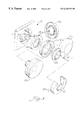
- FIG. 1 is an exploded perspective view of preferred embodiment of a shaft assembly according to the present invention
- FIG.2 is a partial cross-sectional view of a shaft assembly according to a preferred embodiment of the present invention.
- FIG. 3 is a partial cross-sectional view of the shaft assembly as in FIG. 2;
- FIG. 4 is a partial cross-sectional view of the shaft assembly as in FIG. 2;
- FIG. 5 is an exploded view of a shaft assembly according to a preferred embodiment of the present invention.
- FIG. 6 is a partial cross-sectional view of the shaft assembly as in FIG. 5;
- FIG. 7 is a partial cross-sectional view of the shaft assembly as in FIG. 5;
- FIG. 8 is a partial cross-sectional view of a shaft assembly according to a preferred embodiment of the present invention.
- FIG. 9 is a partial exploded view of a shaft assembly according to a preferred embodiment of the present invention.
- FIG. 10 is a partial perspective view of the shaft assembly as in FIG. 9.
- FIG. 11 is a partial cross-sectional view of the shaft assembly as in FIG. 9 .
- a speed reducer 10 includes a housing 12 and an output shaft 14 extending through a bore 16 in the housing.
- the output shaft is driven by an input shaft surrounded by a bell portion 17 of housing 12 .
- speed reducers are shown in the illustrated embodiments herein, it should be understood that this is for exemplary purposes only and that any suitable shaft assembly may be employed within the present invention.
- Seal 18 extends between shaft 14 and the inner circumference of bore 16 .
- Seal 18 includes a rigid outer portion 20 secured to the inner circumference of bore 16 by an interference fit and an elastomeric portion 22 extending from rigid portion 20 to shaft 14 .
- Rigid portion 20 may be formed from any suitable material, for example steel or hard polymer materials.
- Elastomeric portion 22 may be formed from any suitable elastomer material. Elastomeric portion 22 deflects axially inward, with respect to shaft 14 , toward an interior area 24 of speed reducer 10 as portion 22 extends from rigid portion 20 to engage shaft 14 .
- seal 18 is able to retain lubricant in area 24 while effectively preventing entrance of external contaminants.
- an auxiliary seal comprised of a second annular seal member 26 and a third annular seal member 28 is placed over shaft 14 .
- a hollow tool 30 is then placed over shaft 14 and hammered axially inward, as indicated by arrow 32 , to drive the second and third members into position as shown in FIG. 4 .
- An inner circumferential surface 36 of second member 26 establishes an interference fit with shaft 14 , and second member 26 therefore rotates with the shaft.
- An outer circumferential surface 38 sufficiently clears an inner circumferential 40 of third member 28 to allow relative rotation between the second and third members.
- An outer circumferential surface 42 of third member 28 forms an interference fit with the internal circumference of bore 16 .
- An annular lip portion 44 of third member 28 abuts a radially extending edge 46 of bore 16 .
- third member 28 and annular seal 18 are rotationally fixed to housing 12 , while second member 26 is rotationally fixed to shaft 14 .
- Third member 28 includes a first annular portion 48 extending between housing 12 and second member 26 and a second annular portion 50 extending from the housing to the shaft, thereby forming a groove that receives second member 26 .
- the interfaces between second annular portion 50 and shaft 14 , between third member 28 and second member 26 , and between second member 26 and seal 18 form a labyrinth between the exterior area and the point at which elastomeric portion 22 engages the shaft.
- the labyrinth protects the flexible lip portion of seal 18 from dust and other debris and from direct contact with pressurized water used to clean the speed reducer.
- third member 28 in a second embodiment includes a radially extending flange 52 so that the third member may be secured to housing 12 by bolts 54 that extend through holes 56 and threadedly engage tapped holes (not shown) in housing 12 .
- outer circumferential surface 42 of first annular portion 48 need not form an interference fit with the inner circumference of bore 16 .
- second member 26 and third member 28 are formed by a hard plastic material such as DELRIN.
- seal assembly formed by seal 18 and the auxiliary seal may be constructed in any suitable manner and that the embodiments illustrated in the Figures are provided for exemplary purpose only.
- an elastomeric inner portion of seal 18 when present, need not deflect axially inward.
- first and third annular members are rotationally fixed to the housing, and the second member is rotationally fixed to the shaft, it should be understood that these arrangements may be reversed.
- a lip seal such as shown in FIGS. 2-4 is fixed to the housing bore and extends radially inward to engage the shaft.
- a second annular member is rotationally fixed to the shaft axially outward of the elastomeric portion and extends radially outward from the shaft to cover the elastomeric portion. That is, in comparison to the embodiment shown in FIG. 4, third member 28 is omitted, and second member 26 may be extended radially outward.
- a speed reducer 10 in another preferred embodiment of the present invention shown in FIG. 5, includes a shaft 14 extending from a bore 16 of housing 12 .
- an originally installed seal 18 a is removed as indicated by arrow 58 and is replaced by a seal assembly comprising a first seal member 18 b, a second seal member 26 and a third seal member 28 .
- lip seal 18 b and second member 26 are placed on shaft 14 and tapped into position by a first tool 30 a as indicated by arrow 60 .
- Tool 30 a includes a central stem portion 62 that is received within a central bore 64 of shaft 14 to center the tool.
- a cup-shaped outer portion 66 then abuts second member 26 as shown in phantom in FIG. 6 .
- Hammer blows received at the back of tool 30 a thus push lip seal 18 b and second member 26 into position about shaft 14 .
- lip seal 18 b includes a rigid outer portion 20 and an elastomeric inner portion 22 that deflects axially inward as it extends from the rigid outer portion to engage the shaft. Lubricant may be maintained in an interior area 24 defined axially inward of seal 18 b.
- Second member 26 includes a first annular portion 66 extending between housing 12 and outer portion 20 of lip seal 18 b. Annular portion 66 defines an outer circumferential surface 68 received by bore 16 in an interference fit to rotationally fix second member 26 to the housing. The outer portion of the lip seal is, in turn, received by annular portion 66 in an interference fit. Thus, the lip seal may be pressed into annular portion 66 prior to mounting onto shaft 14 so that the lip seal and second member may be installed together.
- a second annular portion 70 of second member 26 defines a first inner circumferential surface 72 and a second inner circumferential surface 74 axially and radially outward of surface 72 .
- a machine shaft (not shown) is inserted into the bore of shaft 14 and is secured by set screws 76 .
- third annular member 28 were to be placed on shaft 14 at the same time as seal 18 b and second member 26 , it would cover the set screws and prevent their tightening onto the machine shaft. Accordingly, following the placement of seal 18 b and second member 26 on shaft 14 , third member 28 is placed over the machine shaft, which is then inserted into the bore of shaft 14 and secured to shaft 14 by the set screws. An operator may then slide third member 28 up to second member 26 and drive it into position by a tool 30 b.
- Tool 30 b includes a cut out portion 78 to receive the machine shaft and/or shaft 14 so that the tool may be placed against third member 28 as indicated by arrow 80 .
- Third member 28 rotates with shaft 14 , while second member 26 and lip seal 18 b are fixed to the housing.
- Third member 28 defines an inner circumference 81 that forms an interference fit with shaft 14 as member 28 is tapped onto the shaft by hammer blows to tool 30 b. It also includes a first annular portion 82 defining an outer circumferential surface 84 and a second annular portion 86 defining an outer circumferential surface 88 . Referring also to FIG. 8, as shown at the right hand side of gear reducer 10 , first annular portion 82 is received within inner circumferential surface 72 of second member 26 , and second annular portion 86 is received within surface 74 .
- the second and third members form interengaging grooves, and a labyrinth is formed between second member 26 and third member 28 and between third member 28 and seal 18 b from the exterior to the point at which seal 18 b engages shaft 14 .
- speed reducer 10 includes a central shaft 14 extending entirely though housing 12 so that the reducer may be positioned at a desired axial point on a machine shaft. That is, the speed reducer may be slidably moved on the machine shaft to properly position the speed reducer with respect to an input drive shaft (not shown). If, however, the machine shaft does not extend entirely through shaft 14 , an end cap 90 may be used to cover bore 16 and the open end of shaft 14 .
- Cap 90 includes an annular flange portion 92 surrounding a central portion 94 .
- Flange 92 includes an inwardly curving edge that is received within a gap defined between housing 12 and an annular lip 96 of annular portion 86 of second member 26 .
- cap 90 is axially fixed to the housing through the engagement of opposing lips formed by the cap and the seal assembly.
- the opposing lips on the cap and seal need not be continuous.
- the cap lip may comprise fingers received in spaced apart recesses in the housing or seal.
- the cap is preferably made from a flexible polymer material so that it may be removed.
- cap 90 protects annular lip portion 22 .
- cap 90 may be used to cover bore 16 even where third member 28 is present, as indicated in phantom at the right hand side of FIG. 8 .
- a speed reducer 10 includes an output shaft 14 disposed in a housing 12 .
- one or two ends may be connected to a machine shaft.
- Speed reducers such as illustrated in these and other figures herein, should be well understood in this art and are therefore not discussed in detail. It should be understood, however, that any suitable means for attaching the machine shaft to the output shaft may be used.
- the interior bore of shaft 14 is tapered, with the diameter expanding outward towards the shaft's end.
- An attachment collar 98 includes a central section 100 received in the shaft bore and having an outer circumferential surface 102 defining a taper that corresponds to the shaft taper.
- Collar 98 defines a radial cut 104 so that compression of the collar reduces the diameter of the collar's central bore 106 .
- the diameter of bore 106 is reduced as the outer tapered surface 102 of collar 98 slides down against the inner tapered surface of shaft 14 , thus securing a machine shaft (not shown) to shaft 14 .
- Collar 98 is rotationally fixed to shaft 14 by friction or other means.
- Collar 98 includes an annular flange 107 having holes through which three bolts 108 extend. Bolts 108 threadedly engage holes in a ring 110 axially retained on shaft 14 by a clip 112 . As bolts 108 are tightened into ring 110 , collar 98 is pulled axially inward into shaft 14 , thus tightening the collar onto the machine shaft.
- An annular seal 114 is rotationally fixed to housing 12 in bore 16 and retains lubricant within interior area 24 of gear reducer 10 .
- an annular ring 116 is received about ring 110 and flange 107 .
- Ring 116 is attached to housing 12 by screws 118 received in threaded holes 120 tapped into housing 12 .
- Ring 116 may be made, for example, from a metal or a hard polymer material such as DELRIN.
- ring 116 is attached to the housing block axially and radially outward of bore 16 , it may also be considered an extension of the bore from the block so that flange 107 and ring 110 form annular members creating a labyrinth between the exterior area and seal 114 .
- the present invention may be embodied in a variety of shaft assemblies in which a rotatable shaft is disposed in a housing and within a bore in the housing extending between the exterior area and an interior area.
- the present invention is not limited to motors and speed reducers, and the embodiments depicted are presented by way of example only and are not intended as limitations upon the present invention.
- the present invention is not limited to these embodiments since modifications can be made. Therefore, it is contemplated that any and all such embodiments are included in the present invention as may fall within the literal or equivalent scope of the appended claims.
Abstract
Description
Claims (23)
Priority Applications (1)
| Application Number | Priority Date | Filing Date | Title |
|---|---|---|---|
| US09/186,922 US6325379B1 (en) | 1998-11-06 | 1998-11-06 | Shaft assembly having improved seal |
Applications Claiming Priority (1)
| Application Number | Priority Date | Filing Date | Title |
|---|---|---|---|
| US09/186,922 US6325379B1 (en) | 1998-11-06 | 1998-11-06 | Shaft assembly having improved seal |
Publications (1)
| Publication Number | Publication Date |
|---|---|
| US6325379B1 true US6325379B1 (en) | 2001-12-04 |
Family
ID=22686848
Family Applications (1)
| Application Number | Title | Priority Date | Filing Date |
|---|---|---|---|
| US09/186,922 Expired - Fee Related US6325379B1 (en) | 1998-11-06 | 1998-11-06 | Shaft assembly having improved seal |
Country Status (1)
| Country | Link |
|---|---|
| US (1) | US6325379B1 (en) |
Cited By (2)
| Publication number | Priority date | Publication date | Assignee | Title |
|---|---|---|---|---|
| US20030102632A1 (en) * | 2001-11-30 | 2003-06-05 | Oprea Duta | Oil seal journal texturing and method thereof |
| US9822818B1 (en) | 2016-07-13 | 2017-11-21 | Baldor Electric Company | Bearing assembly with combination set screw and concentric shaft locking mechanism |
Citations (41)
| Publication number | Priority date | Publication date | Assignee | Title |
|---|---|---|---|---|
| US2003000A (en) * | 1930-12-10 | 1935-05-28 | Wagner Electric Corp | Seal for dynamo electric machines |
| US2571352A (en) * | 1945-03-29 | 1951-10-16 | Christiane Ganna Fast | Shaft seal |
| US3325175A (en) | 1965-02-05 | 1967-06-13 | Dodge Mfg Corp | Shaft seal with multiple lips |
| US3499654A (en) | 1966-01-17 | 1970-03-10 | Reliance Electric Co | Bearing-shaft sealing structure |
| US3810636A (en) | 1972-02-14 | 1974-05-14 | Reliance Electric Co | Bearing sealing structure |
| US3934953A (en) | 1974-05-03 | 1976-01-27 | Reliance Electric Company | Shaft bearing and method of assembling the same |
| US3942849A (en) | 1974-09-23 | 1976-03-09 | Reliance Electric Company | Auxiliary sealing structure for a shaft bearing |
| US4049281A (en) | 1974-10-07 | 1977-09-20 | Garlock Inc. | Unitized dual lip seal method |
| US4079947A (en) * | 1976-09-23 | 1978-03-21 | R. A. Lister & Company Limited | Liquid sealing device |
| EP0051170A1 (en) | 1980-10-31 | 1982-05-12 | RIV-SKF OFFICINE DI VILLAR PEROSA S.p.A | A sealing assembly including axial and radial lips and a labyrinth |
| US4348067A (en) | 1980-03-03 | 1982-09-07 | Reliance Electric Company | Bearing seal |
| US4411437A (en) | 1982-07-14 | 1983-10-25 | Reliance Electric Company | Seal with face-to-face flat metal sealing washers |
| GB2136891A (en) | 1983-02-12 | 1984-09-26 | Nippon Seiko Kk | Sealing device assembly |
| US4575265A (en) | 1980-05-27 | 1986-03-11 | Reliance Electric Company | Seal for shaft bearings |
| US4580789A (en) * | 1984-10-23 | 1986-04-08 | Ludlow Industries, Inc. | Shaft seal construction for bin level indicators |
| US4592666A (en) | 1982-06-03 | 1986-06-03 | Forsheda Ab | Sealing device for sealing a bearing |
| US4632404A (en) | 1984-07-09 | 1986-12-30 | Skf Gmbh | Seal for rolling bearing |
| US4763904A (en) | 1986-10-06 | 1988-08-16 | Reliance Electric Company | Sealing apparatus |
| US4792242A (en) | 1987-01-28 | 1988-12-20 | Riv-Skf Officine Di Villar Perosa S.P.A. | Tight bearing suitable for exceptionally heavy duty conditions |
| US4832511A (en) | 1988-08-16 | 1989-05-23 | Reliance Electric Company | High efficiency seal devices for shaft bearings |
| US4863292A (en) | 1988-03-03 | 1989-09-05 | Fag Kugelfischer Georg Schafer (Kgaa) | Seal for antifriction bearings |
| US4875786A (en) | 1988-12-29 | 1989-10-24 | Reliance Electric Company | Snap-ring with pin release seal |
| FR2631672A1 (en) | 1988-05-17 | 1989-11-24 | Roulements Soc Nouvelle | Rotating seal in contact with a metal support framework |
| US4906111A (en) | 1986-10-06 | 1990-03-06 | Martinie Howard W | Auxiliary sealing system |
| US4943068A (en) * | 1987-07-20 | 1990-07-24 | Mather Seal Company | Unitized exclusion seal |
| EP0388258A1 (en) | 1989-03-14 | 1990-09-19 | S.N.R. Roulements | Sealing between two coaxial parts |
| US5011301A (en) | 1986-10-06 | 1991-04-30 | Reliance Electric Company | Auxiliary sealing system |
| US5022659A (en) | 1988-12-27 | 1991-06-11 | The Timken Company | Seal assembly for antifriction bearings |
| US5201533A (en) | 1992-07-20 | 1993-04-13 | General Motors Corporation | Unitized seal with extra sealing contact and method of making |
| US5207436A (en) | 1992-07-13 | 1993-05-04 | General Motors Corporation | Low friction unitized seal |
| US5259628A (en) | 1992-07-23 | 1993-11-09 | Reliance Electric Industrial Company | Seal assembly |
| US5387040A (en) | 1993-04-30 | 1995-02-07 | Reliance Electric Industrial Company | Sealing system |
| US5489156A (en) | 1994-12-19 | 1996-02-06 | Reliance Electric Industrial Co. | Bearing assembly utilizing improved clamping arrangement |
| US5529403A (en) | 1994-12-19 | 1996-06-25 | Reliance Electric Industrial Company | Bearing assembly |
| US5536090A (en) | 1995-03-15 | 1996-07-16 | Reliance Electric Industrial Company | Expansion bearing having improved lubrication arrangement |
| US5690471A (en) * | 1995-09-29 | 1997-11-25 | Aisin Seiki K.K. | Water pump |
| US5704719A (en) * | 1996-07-01 | 1998-01-06 | Emerson Power Transmission Corp. | Street sweeper bearing with wear resistant resiliently biased face seal |
| US5967524A (en) * | 1993-05-21 | 1999-10-19 | Jm Clipper Corporation | Hybrid seal device |
| US5996542A (en) * | 1997-06-21 | 1999-12-07 | Perkins Engines Company Limited | Rotary shaft sealing system |
| US6050571A (en) * | 1997-01-17 | 2000-04-18 | Ina Walzlager Schaeffler Ohg | Sealing arrangement for a cardan spider bushing |
| US6059292A (en) * | 1997-05-08 | 2000-05-09 | Reliance Electric Industrial Company | Speed reducer apparatus having auxiliary seal assembly |
-
1998
- 1998-11-06 US US09/186,922 patent/US6325379B1/en not_active Expired - Fee Related
Patent Citations (42)
| Publication number | Priority date | Publication date | Assignee | Title |
|---|---|---|---|---|
| US2003000A (en) * | 1930-12-10 | 1935-05-28 | Wagner Electric Corp | Seal for dynamo electric machines |
| US2571352A (en) * | 1945-03-29 | 1951-10-16 | Christiane Ganna Fast | Shaft seal |
| US3325175A (en) | 1965-02-05 | 1967-06-13 | Dodge Mfg Corp | Shaft seal with multiple lips |
| US3499654A (en) | 1966-01-17 | 1970-03-10 | Reliance Electric Co | Bearing-shaft sealing structure |
| US3810636A (en) | 1972-02-14 | 1974-05-14 | Reliance Electric Co | Bearing sealing structure |
| US3934953A (en) | 1974-05-03 | 1976-01-27 | Reliance Electric Company | Shaft bearing and method of assembling the same |
| US3942849A (en) | 1974-09-23 | 1976-03-09 | Reliance Electric Company | Auxiliary sealing structure for a shaft bearing |
| US4049281A (en) | 1974-10-07 | 1977-09-20 | Garlock Inc. | Unitized dual lip seal method |
| US4079947A (en) * | 1976-09-23 | 1978-03-21 | R. A. Lister & Company Limited | Liquid sealing device |
| US4348067A (en) | 1980-03-03 | 1982-09-07 | Reliance Electric Company | Bearing seal |
| US4776709A (en) | 1980-05-27 | 1988-10-11 | Reliance Electric Company | Seal for shaft bearings |
| US4575265A (en) | 1980-05-27 | 1986-03-11 | Reliance Electric Company | Seal for shaft bearings |
| EP0051170A1 (en) | 1980-10-31 | 1982-05-12 | RIV-SKF OFFICINE DI VILLAR PEROSA S.p.A | A sealing assembly including axial and radial lips and a labyrinth |
| US4592666A (en) | 1982-06-03 | 1986-06-03 | Forsheda Ab | Sealing device for sealing a bearing |
| US4411437A (en) | 1982-07-14 | 1983-10-25 | Reliance Electric Company | Seal with face-to-face flat metal sealing washers |
| GB2136891A (en) | 1983-02-12 | 1984-09-26 | Nippon Seiko Kk | Sealing device assembly |
| US4632404A (en) | 1984-07-09 | 1986-12-30 | Skf Gmbh | Seal for rolling bearing |
| US4580789A (en) * | 1984-10-23 | 1986-04-08 | Ludlow Industries, Inc. | Shaft seal construction for bin level indicators |
| US4763904A (en) | 1986-10-06 | 1988-08-16 | Reliance Electric Company | Sealing apparatus |
| US5011301A (en) | 1986-10-06 | 1991-04-30 | Reliance Electric Company | Auxiliary sealing system |
| US4906111A (en) | 1986-10-06 | 1990-03-06 | Martinie Howard W | Auxiliary sealing system |
| US4792242A (en) | 1987-01-28 | 1988-12-20 | Riv-Skf Officine Di Villar Perosa S.P.A. | Tight bearing suitable for exceptionally heavy duty conditions |
| US4943068A (en) * | 1987-07-20 | 1990-07-24 | Mather Seal Company | Unitized exclusion seal |
| US4863292A (en) | 1988-03-03 | 1989-09-05 | Fag Kugelfischer Georg Schafer (Kgaa) | Seal for antifriction bearings |
| FR2631672A1 (en) | 1988-05-17 | 1989-11-24 | Roulements Soc Nouvelle | Rotating seal in contact with a metal support framework |
| US4832511A (en) | 1988-08-16 | 1989-05-23 | Reliance Electric Company | High efficiency seal devices for shaft bearings |
| US5022659A (en) | 1988-12-27 | 1991-06-11 | The Timken Company | Seal assembly for antifriction bearings |
| US4875786A (en) | 1988-12-29 | 1989-10-24 | Reliance Electric Company | Snap-ring with pin release seal |
| EP0388258A1 (en) | 1989-03-14 | 1990-09-19 | S.N.R. Roulements | Sealing between two coaxial parts |
| US5207436A (en) | 1992-07-13 | 1993-05-04 | General Motors Corporation | Low friction unitized seal |
| US5201533A (en) | 1992-07-20 | 1993-04-13 | General Motors Corporation | Unitized seal with extra sealing contact and method of making |
| US5259628A (en) | 1992-07-23 | 1993-11-09 | Reliance Electric Industrial Company | Seal assembly |
| US5387040A (en) | 1993-04-30 | 1995-02-07 | Reliance Electric Industrial Company | Sealing system |
| US5967524A (en) * | 1993-05-21 | 1999-10-19 | Jm Clipper Corporation | Hybrid seal device |
| US5529403A (en) | 1994-12-19 | 1996-06-25 | Reliance Electric Industrial Company | Bearing assembly |
| US5489156A (en) | 1994-12-19 | 1996-02-06 | Reliance Electric Industrial Co. | Bearing assembly utilizing improved clamping arrangement |
| US5536090A (en) | 1995-03-15 | 1996-07-16 | Reliance Electric Industrial Company | Expansion bearing having improved lubrication arrangement |
| US5690471A (en) * | 1995-09-29 | 1997-11-25 | Aisin Seiki K.K. | Water pump |
| US5704719A (en) * | 1996-07-01 | 1998-01-06 | Emerson Power Transmission Corp. | Street sweeper bearing with wear resistant resiliently biased face seal |
| US6050571A (en) * | 1997-01-17 | 2000-04-18 | Ina Walzlager Schaeffler Ohg | Sealing arrangement for a cardan spider bushing |
| US6059292A (en) * | 1997-05-08 | 2000-05-09 | Reliance Electric Industrial Company | Speed reducer apparatus having auxiliary seal assembly |
| US5996542A (en) * | 1997-06-21 | 1999-12-07 | Perkins Engines Company Limited | Rotary shaft sealing system |
Non-Patent Citations (2)
| Title |
|---|
| Catalog 4000 US, pp. 722, 723, 1991, United States. |
| Reliance Electric Company, 2 pages from catalog, 1996, United States. |
Cited By (2)
| Publication number | Priority date | Publication date | Assignee | Title |
|---|---|---|---|---|
| US20030102632A1 (en) * | 2001-11-30 | 2003-06-05 | Oprea Duta | Oil seal journal texturing and method thereof |
| US9822818B1 (en) | 2016-07-13 | 2017-11-21 | Baldor Electric Company | Bearing assembly with combination set screw and concentric shaft locking mechanism |
Similar Documents
| Publication | Publication Date | Title |
|---|---|---|
| US5716277A (en) | Seal for a universal joint trunnion | |
| EP1898132A1 (en) | Sealing device | |
| US5454647A (en) | Seal for package bearing | |
| CA2083565A1 (en) | Shaft-wall seal with elastomerically protected reinforcement rings | |
| EP3184864B1 (en) | Sealing structure | |
| ES2161121B1 (en) | STREAM WITH A SECTION THAT INCLUDES ANNULAR FOLDINGS AND CLAMPING AREAS | |
| EP1281882A4 (en) | Sealing device | |
| KR870001428A (en) | Ring seal | |
| EP0926408A3 (en) | Sealing apparatus | |
| CA2152991A1 (en) | Seal for rolling bearings | |
| US5529403A (en) | Bearing assembly | |
| JP4471079B2 (en) | Sealing device | |
| CA2472166A1 (en) | Externally mountable spiral adaptor | |
| CA2102472A1 (en) | Seal Arrangement | |
| US6325379B1 (en) | Shaft assembly having improved seal | |
| US20090011841A1 (en) | Thrust washer for universal joint cross | |
| US6282768B1 (en) | Tool and seal cover for shaft assembly | |
| US7182346B2 (en) | Multistage oil seal against different cutting fluids for a machine tool motor | |
| EP1759882A3 (en) | Wheel hub rolling element bearing assembly with sealing arrangement | |
| US6171197B1 (en) | Transmission coupling device | |
| US1631557A (en) | External bearing-adjusting means | |
| CA2170792A1 (en) | Anti-leakage device | |
| AU2006235185B2 (en) | Plastic ring for removeably fixing a round shank chisel in a chisel bush | |
| JP2018529050A (en) | Protective ring, seal structure, and journal cloth assembly | |
| JPH03117727A (en) | Protecting device for rotary joint |
Legal Events
| Date | Code | Title | Description |
|---|---|---|---|
| AS | Assignment |
Owner name: RELIANCE ELECTRIC INDUSTRIAL COMPANY, OHIO Free format text: ASSIGNMENT OF ASSIGNORS INTEREST;ASSIGNOR:RAPP, ROBERT J.;REEL/FRAME:009572/0781 Effective date: 19981105 |
|
| FEPP | Fee payment procedure |
Free format text: PAYOR NUMBER ASSIGNED (ORIGINAL EVENT CODE: ASPN); ENTITY STATUS OF PATENT OWNER: LARGE ENTITY |
|
| FPAY | Fee payment |
Year of fee payment: 4 |
|
| AS | Assignment |
Owner name: BNP PARIBAS, NEW YORK Free format text: SECURITY AGREEMENT;ASSIGNOR:RELIANCE ELECTRIC COMPANY;REEL/FRAME:019140/0013 Effective date: 20070131 |
|
| AS | Assignment |
Owner name: RELIANCE ELECTRIC TECHNOLOGIES, LLC, OHIO Free format text: ASSIGNMENT OF ASSIGNORS INTEREST;ASSIGNOR:RELIANCE ELECTRIC INDUSTRIAL COMPANY;REEL/FRAME:020571/0539 Effective date: 20000324 |
|
| REMI | Maintenance fee reminder mailed | ||
| LAPS | Lapse for failure to pay maintenance fees | ||
| STCH | Information on status: patent discontinuation |
Free format text: PATENT EXPIRED DUE TO NONPAYMENT OF MAINTENANCE FEES UNDER 37 CFR 1.362 |
|
| FP | Lapsed due to failure to pay maintenance fee |
Effective date: 20091204 |