US63243A - Island - Google Patents
Island Download PDFInfo
- Publication number
- US63243A US63243A US63243DA US63243A US 63243 A US63243 A US 63243A US 63243D A US63243D A US 63243DA US 63243 A US63243 A US 63243A
- Authority
- US
- United States
- Prior art keywords
- spindle
- shaft
- latch
- machine
- screw
- Prior art date
- Legal status (The legal status is an assumption and is not a legal conclusion. Google has not performed a legal analysis and makes no representation as to the accuracy of the status listed.)
- Expired - Lifetime
Links
- 241000220010 Rhode Species 0.000 description 1
- 238000013459 approach Methods 0.000 description 1
- 238000010276 construction Methods 0.000 description 1
- 230000001419 dependent effect Effects 0.000 description 1
- 230000000694 effects Effects 0.000 description 1
- 210000001364 upper extremity Anatomy 0.000 description 1
Images
Classifications
-
- B—PERFORMING OPERATIONS; TRANSPORTING
- B23—MACHINE TOOLS; METAL-WORKING NOT OTHERWISE PROVIDED FOR
- B23G—THREAD CUTTING; WORKING OF SCREWS, BOLT HEADS, OR NUTS, IN CONJUNCTION THEREWITH
- B23G1/00—Thread cutting; Automatic machines specially designed therefor
- B23G1/02—Thread cutting; Automatic machines specially designed therefor on an external or internal cylindrical or conical surface, e.g. on recesses
- B23G1/04—Machines with one working-spindle
-
- F—MECHANICAL ENGINEERING; LIGHTING; HEATING; WEAPONS; BLASTING
- F16—ENGINEERING ELEMENTS AND UNITS; GENERAL MEASURES FOR PRODUCING AND MAINTAINING EFFECTIVE FUNCTIONING OF MACHINES OR INSTALLATIONS; THERMAL INSULATION IN GENERAL
- F16B—DEVICES FOR FASTENING OR SECURING CONSTRUCTIONAL ELEMENTS OR MACHINE PARTS TOGETHER, e.g. NAILS, BOLTS, CIRCLIPS, CLAMPS, CLIPS OR WEDGES; JOINTS OR JOINTING
- F16B5/00—Joining sheets or plates, e.g. panels, to one another or to strips or bars parallel to them
- F16B5/02—Joining sheets or plates, e.g. panels, to one another or to strips or bars parallel to them by means of fastening members using screw-thread
- F16B5/0275—Joining sheets or plates, e.g. panels, to one another or to strips or bars parallel to them by means of fastening members using screw-thread the screw-threaded element having at least two axially separated threaded portions
Definitions
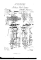
- Figure I is a side elevation of a machine for shaving, niching, and reshaving the heads of screw-blanks.
- Figure 2 is an end elevation.
- Figure 3 is a plan.
- Figure 4 is a longitudinal section, particularly showing the improvement te which this patent relates.
- the invention which is the subject of this patent is applicable to that class of machines for making screws which combine a. uic-lier and ashaver in one.
- the drawings represent the full machine which I employ, and which eontainscertain features of construction and operation which are common to many ⁇ other machines for similar purposes.
- the invention herein described consists in the means employed for causing the spindle, in the jaws of which the screw-blank is griped, to be alternately rotated and brought to a state of rest, to comply with the necessary conditions under which suoli screw-blank must be shaved, nicked, and reshaved.
- two drivingpullcys are commonly used, one of which is .connected with the spindle, to rotate it, and also to put into action the mechanism for shaving the head of the blank, while the other is connected with and operates the mechanism for cutting the nick in such head; the driving-belt beingshifted from one pulley to the other when thc changes are to be made.
- A is the bed which gives support to the various parts et' the machine. Motion is given to the pulley I), in the direction of the arrow, by means of a belt passing around the saine, and from which all the various movements et' the machine are derived.
- D is the spindle, mounted in suitable bearings, B B1, and, so far asthe means are concerned for griping the blank, is not unlike the spindles in common usc in other machines. It is, however, peculiar in this, that it is connected with the shaft D', driven by the pulley I), (figs.
- the rearendot' the spindle also ,enters the hub of the pulley, but tits so loosely as to create no friction between its surface and the inner surface of the hub.
- the rear end ot' the spindle D is provided with a transverse slot, g, in which is litted a movable latch, f, the slot being of suhcient depth to allow such latch to be entirely sheathed in the spindle when th; springj', which tends to force it outward, is compressed.
- the axis ofthe shaft Dl is made hollow, and. is fitted with a rod, b, (iig. 4.)
- the forward end of this rod is connected with the latch c in any convenienty way, so that, by the application of pressure to the rear cud of it which protrudes beyond the' shaft D, (as shown in iig. 1,) the latch will be forced further into the slot g, and the connection between the spindle and the driving power bc broken.
- Z is the shaft upon which the various cams for eecting the diicrent changes of movement are mounted.
- This shaft is so timed that it will revolve once for every thirty-two revolutions of the driving-gear, O, a'nd it carries a wheel, Z, which has a projectingl piece, h, upon its side.
- a fulcrum is also attached to the side ofthe standard B2 a fulcrum, to which is pivoted the lever m, the face of which, near its upper extremity, bears against the end of the rod I), and its lower end is hinged to the shaft t', which is itted to slide endwise in bearings made in the standards B and B2 of the frame.
- the shaft t' carries a projecting armer stud, j, against the surface of which the projection 7L on the cam-wheel Z acts, in the course of the revolution of the latter, and causes thereby the lever m to perform its function as above described. So long as lthe face of the stud z' con- .tinues in contact with the projecting surface ot' J., the spindle D will b at rest; but so soon as the same, in the course of the revolution of thc shaft Z, is moved away from the stud-pin, the springf will act to re-estahlish the connection between the spindle and the driving power.
Landscapes
- Engineering & Computer Science (AREA)
- General Engineering & Computer Science (AREA)
- Mechanical Engineering (AREA)
- Processing Of Stones Or Stones Resemblance Materials (AREA)
Description
NICHOLAS B. HADLEY, CF PROVIDENCE, RHODE ISLAND, ASSIGNCII TC TI-IE lN'lERNi-YFICNAL SCREW COMFANY.
Letters Patent No. 63,243, dated M'a'rct 26, 1867.
IMTBOVEMENT IN MACHINERY FOR NICKING SCREWS.
TO ALLl WHO Il) MAY CONCERN:
Beit known that I, NICHOLAS B. I-IADLEY, of thc city and county of Providence, in the State ol" Rhode Island, have invented a new and usei'ul Improvement in Machines for Nicking and Dressing the Heads of Screw- Blanks; and I do hereby declare that the following specification, taken in connection with the drawings making a, part of the same, is a full, clear, and exact description thereof.
Figure I is a side elevation of a machine for shaving, niching, and reshaving the heads of screw-blanks.
Figure 2 is an end elevation.
Figure 3 is a plan.
Figure 4 is a longitudinal section, particularly showing the improvement te which this patent relates.
Figures 5 and 6 are details of the same.
The invention which is the subject of this patent is applicable to that class of machines for making screws which combine a. uic-lier and ashaver in one. The drawings represent the full machine which I employ, and which eontainscertain features of construction and operation which are common to many `other machines for similar purposes. The invention herein described consists in the means employed for causing the spindle, in the jaws of which the screw-blank is griped, to be alternately rotated and brought to a state of rest, to comply with the necessary conditions under which suoli screw-blank must be shaved, nicked, and reshaved. As, however, this part of my invention may be used independently of any other improvements existing in the machine, and may be also applied to any other screw machine of this class, I shall confine myself, in the present specification, to a description of so much ot' the machine as I deem necessary7 to communicate a clear understanding of the particular invention herein claimed.
In other machines for performing the operations of shaving and niching` the head of a screw-blank, two drivingpullcys are commonly used, one of which is .connected with the spindle, to rotate it, and also to put into action the mechanism for shaving the head of the blank, while the other is connected with and operates the mechanism for cutting the nick in such head; the driving-belt beingshifted from one pulley to the other when thc changes are to be made.
One of the chief objections which has been expressed against such combined machines is, that the proper relative operation of these two sets of mechanism to each other cannot he relied upon with certainty, inasmuch as the same is dependent upon the question whether the belt shifts promptly and without slippage from one pulley to the other.
In the accompanying drawings, A is the bed which gives support to the various parts et' the machine. Motion is given to the pulley I), in the direction of the arrow, by means of a belt passing around the saine, and from which all the various movements et' the machine are derived. D is the spindle, mounted in suitable bearings, B B1, and, so far asthe means are concerned for griping the blank, is not unlike the spindles in common usc in other machines. It is, however, peculiar in this, that it is connected with the shaft D', driven by the pulley I), (figs. I and 4,) by means of a springlatch, so that at the proper times, when the two are united, the spindle D will turn withthe shaft D', but when the two are unlatched the spindle will be left at rest. rIhe arrangement is shown moreiclearly in g. d, where it will be seen that the axes of the spindle D and the shaft D are coincident. rIhe toothed wheel, O, (ligs. l, 2, 3,) which communicates motion, in a way hereinafter to be referred to, to the principal cam-shaft governing the unlatching of the spindle, the opening and closing` of the griping jaws, and the bringing?r up ot' the picking saw to the head of the blank, and which also drives the shaft II, upon which the nicking saw is mounted in this instance, is provided with a sleeve, O', (iig. 4,) to which the hub ot' the pulley I) is secured. The end ot' this sleeve is made with a ratchet face, or is provided with equivalent notches, to receive the latch which is connected with the spindle D. The rearendot' the spindle also ,enters the hub of the pulley, but tits so loosely as to create no friction between its surface and the inner surface of the hub. The rear end ot' the spindle D is provided with a transverse slot, g, in which is litted a movable latch, f, the slot being of suhcient depth to allow such latch to be entirely sheathed in the spindle when th; springj', which tends to force it outward, is compressed. So long as the springj" is permitted to act, the 'y latch c will he engaged with a notch or notches in the end ot' the sleeve, and thc spindle will parta-he of its motion; but when the latch is pushed into the slot g so far that its face does not protrude beyond the end of the spindle, all connection between the spindle and the parts in motion will be broken, and the spindle will rest in its bearings. In order to break this connection at the proper time in the operation of the machine, the
following devices and combinations are in this instance employed: The axis ofthe shaft Dl is made hollow, and. is fitted with a rod, b, (iig. 4.) The forward end of this rod is connected with the latch c in any convenienty way, so that, by the application of pressure to the rear cud of it which protrudes beyond the' shaft D, (as shown in iig. 1,) the latch will be forced further into the slot g, and the connection between the spindle and the driving power bc broken.
rJhe precise arrangement of 'thc parts as here described is not essential. Various ways maybe employed for performing?r the same result, but so longr as they involve the use of a movable latch, or its equivalent, they will be within the principle which characterizes my invention.
In the organized machine, as I have arranged it, the connection between the spindle D and its moving,r power is broken by the following means:
In fig. l, Z is the shaft upon which the various cams for eecting the diicrent changes of movement are mounted. This shaft is so timed that it will revolve once for every thirty-two revolutions of the driving-gear, O, a'nd it carries a wheel, Z, which has a projectingl piece, h, upon its side. There is also attached to the side ofthe standard B2 a fulcrum, to which is pivoted the lever m, the face of which, near its upper extremity, bears against the end of the rod I), and its lower end is hinged to the shaft t', which is itted to slide endwise in bearings made in the standards B and B2 of the frame. The shaft t' carries a projecting armer stud, j, against the surface of which the projection 7L on the cam-wheel Z acts, in the course of the revolution of the latter, and causes thereby the lever m to perform its function as above described. So long as lthe face of the stud z' con- .tinues in contact with the projecting surface ot' J., the spindle D will b at rest; but so soon as the same, in the course of the revolution of thc shaft Z, is moved away from the stud-pin, the springf will act to re-estahlish the connection between the spindle and the driving power. It will thus be seen that, while the operation of shaving the head of the screw-blank is to be performed, the spindle D will be revolved; but that when the saw is called into action to cut the nick, the spindle will be at rest, but will recommence its rotation so soon as the saw is withdrawn and the cutter approaches to reshave the head, and this will be done while the driving-pulley is revolving continuously. y
It is obvious that the arrangement here shown for operating thc latch c through the rod 6 may be greatly varied, and that the same result can be produced by combining the rod b with any portion ot` the machine which has a motion at the time when the connection is desired to be broken, as, for instance, with th/e rocker-shaft which carries the shaving tool, or with the moving` carriage which carries the niclcing saw, and so arranged, by a suitable system ot" connecting levers, that as the cutter retreats, or as-tlre saw advances, the rod will be eotemporaneously moved in the proper direction to effect the disconnection. The arrangement which I have shown, however, I consider to bc the bestand simplest for the purpose.
What I claim as my invention, and desire Ato secure by Letters Iatent, is y Unitingr the spindle D with its driving power by means of the movable latch connection e, or its equivalent/arranged and operating substantially as described for the purposes specified.
NICHOLAS Il. HADLEY. Witnesses:
GEORGE Bl BARRows, WILLIAM4 W. Riemen.
Publications (1)
| Publication Number | Publication Date |
|---|---|
| US63243A true US63243A (en) | 1867-03-26 |
Family
ID=2132776
Family Applications (1)
| Application Number | Title | Priority Date | Filing Date |
|---|---|---|---|
| US63243D Expired - Lifetime US63243A (en) | Island |
Country Status (1)
| Country | Link |
|---|---|
| US (1) | US63243A (en) |
-
0
- US US63243D patent/US63243A/en not_active Expired - Lifetime
Similar Documents
| Publication | Publication Date | Title |
|---|---|---|
| US63243A (en) | Island | |
| US371654A (en) | dundeedale | |
| US15907A (en) | Gimlet-handle | |
| US641380A (en) | Automatic machine-chuck. | |
| US13307A (en) | And mortising hubs | |
| US247593A (en) | Edwin allen | |
| US7499A (en) | Improvement in machines for cutting screws | |
| US177976A (en) | Improvement in machines for threading screws | |
| US323892A (en) | wesson | |
| US15467A (en) | bailey | |
| US499979A (en) | field | |
| US81295A (en) | bob in son | |
| US17734A (en) | Machine fob tapping nuts | |
| US80855A (en) | George f | |
| US409909A (en) | Machine for cutting wooden dishes | |
| US61113A (en) | steeetee | |
| US7389A (en) | Apparatus for setting logs in sawmills | |
| US5794A (en) | Improvement in screw-threading machines | |
| US89528A (en) | Improved machine for making screws | |
| US67520A (en) | Improvement in machines | |
| US116880A (en) | Improvement in machines for making screws | |
| US16858A (en) | Machine for unmaking rope or cordage | |
| US446211A (en) | schweizee | |
| US8456A (en) | sloan | |
| US120015A (en) | Improvement in lathe-chucks |