US6317651B1 - Trajectory generation system - Google Patents
Trajectory generation system Download PDFInfo
- Publication number
- US6317651B1 US6317651B1 US09/276,880 US27688099A US6317651B1 US 6317651 B1 US6317651 B1 US 6317651B1 US 27688099 A US27688099 A US 27688099A US 6317651 B1 US6317651 B1 US 6317651B1
- Authority
- US
- United States
- Prior art keywords
- joint
- vector
- manipulator
- requested
- cartesian
- Prior art date
- Legal status (The legal status is an assumption and is not a legal conclusion. Google has not performed a legal analysis and makes no representation as to the accuracy of the status listed.)
- Expired - Lifetime
Links
Images


Classifications
-
- B—PERFORMING OPERATIONS; TRANSPORTING
- B25—HAND TOOLS; PORTABLE POWER-DRIVEN TOOLS; MANIPULATORS
- B25J—MANIPULATORS; CHAMBERS PROVIDED WITH MANIPULATION DEVICES
- B25J9/00—Program-controlled manipulators
- B25J9/16—Program controls
- B25J9/1656—Program controls characterised by programming, planning systems for manipulators
- B25J9/1664—Program controls characterised by programming, planning systems for manipulators characterised by motion, path, trajectory planning
-
- G—PHYSICS
- G05—CONTROLLING; REGULATING
- G05B—CONTROL OR REGULATING SYSTEMS IN GENERAL; FUNCTIONAL ELEMENTS OF SUCH SYSTEMS; MONITORING OR TESTING ARRANGEMENTS FOR SUCH SYSTEMS OR ELEMENTS
- G05B2219/00—Program-control systems
- G05B2219/30—Nc systems
- G05B2219/40—Robotics, robotics mapping to robotics vision
- G05B2219/40495—Inverse kinematics model controls trajectory planning and servo system
-
- G—PHYSICS
- G05—CONTROLLING; REGULATING
- G05B—CONTROL OR REGULATING SYSTEMS IN GENERAL; FUNCTIONAL ELEMENTS OF SUCH SYSTEMS; MONITORING OR TESTING ARRANGEMENTS FOR SUCH SYSTEMS OR ELEMENTS
- G05B2219/00—Program-control systems
- G05B2219/30—Nc systems
- G05B2219/49—Nc machine tool, till multiple
- G05B2219/49384—Control of oscillatory movement like filling a weld, weaving
Definitions
- the present invention relates generally to control methods and systems for robotic manipulators. More particularly, the invention relates to a system for generating robotic manipulator trajectories.
- Performing Cartesian control of robotic manipulators involves interpolating a Cartesian trajectory (position, velocity and acceleration) and converting this Cartesian trajectory into an equivalent joint space state.
- the position conversion is performed using the inverse kinematics mapping of the manipulator.
- the conventional method of computing the joint velocities is by taking the difference between consecutive joint positions and dividing it by the interpolation period. This approach inherently jeopardizes path accuracy at low servo update rates and high accelerations. Furthermore, it can produce non-smooth trajectories.
- the present invention provides a trajectory generation system to operate a robot in response to a motion command.
- the robot is a multi-jointed manipulator with an end-effector that traverses a trajectory.
- a Cartesian trajectory generator converts the motion command into a requested Cartesian positions vector and a requested Cartesian velocities vector.
- a Jacobian matrix of the manipulator defines the relationship between the manipulator joint velocities vector and the manipulator Cartesian velocities vector.
- a requested joint velocities vector is computed from the requested Cartesian velocities vector by means of the inverse of the Jacobian matrix.
- a requested joint positions vector is computed from the requested Cartesian velocities vector by means of inverse kinematics.
- the requested joint velocities vector and requested joint positions vector define a planned state vector for the manipulator.
- FIG. 1 is a two-dimensional view of a stick figure representation of a robotic manipulator
- FIG. 2 is an entity relationship diagram of the components of the presently preferred embodiment
- FIG. 3 is a waveform diagram illustrating a trapezoidal waveform used for weaving
- FIG. 4 is a three dimensional graph of a complex path having a superposed waveform
- FIG. 5 is a three dimensional diagram of the relationship of previous and current weave frames
- FIG. 6 is a datagram illustrating backward recursion of the computed path velocity
- FIGS. 7A-7B is a flow chart illustrating an embodiment of the trajectory generation system.
- FIG. 1 Illustrated in FIG. 1 is a typical multi-jointed robotic manipulator 10 having six degrees of freedom.
- the manipulator 10 extends from a base end 12 to an end effector (not shown) connected to a flange 14 .
- Links 16 , 18 , 20 , 22 , and 24 are coupled from the base end 12 to the flange 14 by joints 26 , 28 , 30 , 32 , 34 , and 36 .
- the manipulator is generally controlled by a motion system that includes hardware and software components for computing trajectories and inputting and displaying data.
- the joints are represented by zo through z5.
- the flange is represented by subscript “F” and the base is represented by subscript “W”.
- the position and orientation of the end effector are typically described relative to some convenient coordinate system.
- some convenient coordinate system For example, for the manipulator 10 it might be convenient to use a fixed Cartesian coordinate system having an origin at a desired location, an x-axis and a y-axis which define a horizontal plane parallel to the base end 12 , and a z-axis perpendicular to the horizontal plane.
- a Cartesian Trajectory Generator 44 receives a motion request 42 directing that the end effector execute a specific motion.
- the Cartesian Trajectory Generator 44 converts the motion request 42 into a requested Cartesian state vector that is comprised of a requested Cartesian velocity vector and a requested Cartesian position vector, steps 72 .
- an Inverse Kinematics determiner 46 computes an equivalent requested joint position vector from the requested Cartesian position vector.
- an inverse Jacobian matrix 48 representing the manipulator configuration is derived.
- the scope of the invention includes pseudo-inverse matrices as well as exact inverses of the Jacobian.
- the manipulator Jacobian matrix 50 from which the inverse is derived, relates the joint velocities to Cartesian velocities at a given configuration:
- ⁇ dot over (X) ⁇ is the vector of Cartesian velocities and ⁇ dot over (q) ⁇ is the vector of joint velocities.
- the requested joint velocity vector is computed using the inverse Jacobian matrix 48. This method results in improved path accuracy at low servo update rates if the servo system is capable of receiving position and velocity state vectors and interpolating from one state vector to the next.
- the Jacobian matrix of a robotic manipulator is the matrix that defines the relationship between the joint velocities and Cartesian velocities.
- the vector of joint velocities is comprised of n elements, where n is the number of joints in the robot.
- the vector of Cartesian velocities is comprised of 6 elements, 3 translational and 3 rotational velocities.
- the Jacobian is square, the number of rows is equal to the number of columns, and generally there is a one-to-one relationship between joint and Cartesian velocities.
- the Jacobian matrix that is not invertible, sometimes resulting in an over-determined system.
- an over-determined system would be manipulators having only 5 joints, wherein control can be exerted only over five degrees of freedom.
- the Jacobian representing a 5 joint manipulator is a 6 ⁇ 5 matrix.
- a 5 joint manipulator is an over-determined system.
- To compute an inverse of a 6 ⁇ 5 Jacobian one degree of freedom must be ignored.
- the spin about the tool approach vector is not controlled, however the scope of the invention includes not controlling other state variables.
- the trajectory generator controls the tool approach vector, which represents 2 degrees of freedom and the Cartesian location (x, y, and z).
- Tool Tool J Tool Tool ⁇ ⁇ ( q . 1 q . 2 q . 3 q . 4 q . 5 )
- the presently preferred embodiment of the invention allows weaving on complex path shapes as well as on blended moves. Weaving is the operation of superposing a wave form on the nominal robot path (illustrated in FIGS. 3 and 4 ).
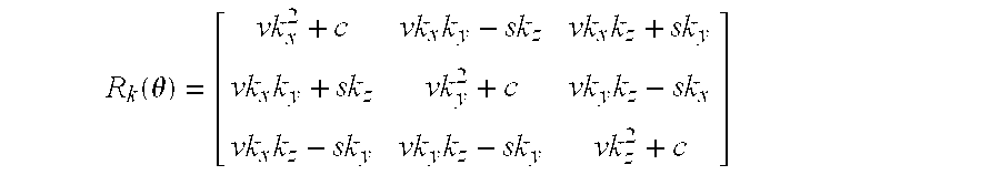
- a weave direction is computed from the tool approach vector and the nominal path direction. When dealing with linear Cartesian moves, the path direction does not change and the weave direction stays constant along the path. However, when dealing with contoured paths, such as blends or spline segments, the path direction changes dynamically. A mechanism is required that allows the weave direction along the path to be changed so that it stays perpendicular to the path. To achieve this a rotation matrix is computed to permit a transformation from the previous path direction to the new path direction. An angle-axis approach is employed to compute the rotation matrix. At step 82, the axis of rotation is determined by the following cross product:
- the path directions are obtained by normalizing the Cartesian velocities, they are not computed explicitly. Since the two path directions are unit vectors, the norm of the axis K is equal to sin( ⁇ ), where ⁇ is the angle, about K, between PrevPath and CurrPath.
- R k ⁇ ( ⁇ ) [ vk x 2 + c vk x ⁇ k y - sk z vk x ⁇ k z + sk y vk x ⁇ k y + sk z vk y 2 + c vk y ⁇ k z - sk x vk x ⁇ k z - sk y vk y ⁇ k z - sk y vk y vk y ⁇ k z - sk y vk z 2 + c ]
- the new weave frame is then computed from the previous weave frame by pre-multiplying it by R k ( ⁇ ), ie:
- CurrWvFr is the current weave frame and PrevWvFr is the previous weave frame.
- the joints of the machine When performing a Cartesian move, the joints of the machine will follow a non-linear path in joint space.
- the joint values must remain within predetermined limits throughout the course of a move, it is not sufficient for the initial and end positions to be within the manipulator's workspace. It is possible that during the middle of a move, the kinematics of the machine will drive the joint values to beyond the specified limits, causing a joint limit violation.
- a manipulator may attempt a circular move where not all of the arc is contained in the workspace.
- the stopping position using full joint deceleration is computed during every interpolation cycle, step 84 .
- Whether the machine can come smoothly to a full stop without violating the joint limits is computed given the machine's actual position, actual velocity, and using joint acceleration limits for the machine. If the computation indicates that the joint limits would be violated, the current interpolation cycle is rejected, and all joints are commanded to come to a stop.
- the Jacobian matrix of a robotic manipulator depends, in general, on the configuration of the machine. Hence, the relationship between the Cartesian and joint velocities is non-linear. During a Cartesian linear move, a constant Cartesian speed may translate to joint speeds that are within the joint speed limits at some times and positions, and violate those limits at other times and positions. This is particularly true when the machine approaches a singular configuration during a Cartesian move. In that case, small Cartesian velocities translate into very large joint velocities.
- the presently preferred embodiment of the invention provides a solution that maintains the path shape while staying within the machine joint speed limit constraints. The solution consists of the following steps in every interpolation period, step 86 of FIG. 7 :
- the machine is most likely in or near a singular configuration. Rather than allow the machine to attempt a large change in position, the joint motions are constrained to be less than a certain maximum given the machine capabilities, step 87 . That is, the change in the joint position is limited to:
- ⁇ dot over (q) ⁇ max is the maximum joint speed and ⁇ t is the interpolation period. is effectively a saturation filter or clamping on the maximum change in joint position per interpolation cycle.
- the presently preferred embodiment of the invention includes an alternative means of ensuring a smooth transition from one side of a singularity to the other.
- the embodiment includes a means for performing a move that is in the null space of the robot Jacobian matrix when the machine is in a singular configuration, 88 .
- a robotic manipulator loses one or more degrees freedom. This sometimes happens because 2 or more joint axes line up. They effectively become one joint. Attempting to proceed directly through a singularity usually results in one or more joints attempting large, instantaneous moves. Examples of when a singularity occurs include when two or more of a machine's joints are aligned and when the determinant of the Jacobian is approximately zero.
- a move is performed that is in the null space of the robot Jacobian matrix when the machine is in a singular configuration.
- the joints of the machine are moved to appropriate destination values that permit the machine to smoothly exit the singularity.
- the joints of the machine are moved in such a way as to keep the Cartesian position of the end effector fixed while changing the joint angles to where they will be when the machine exits the singularity. This results in joint moves that do not affect the end-effector location and orientation.
- a null space move with respect to this position will move joints 4 and 6 in opposite directions so that the end-effector preserves its location and orientation at any instant during the move.
- the motion segment may be too small to allow for acceleration to full speed.
- three small motion segments have been requested.
- the machine In order for the machine to safely decelerate to a stop, further assume that the machine must begin decelerating during the second motion segment. This requirement limits the maximum speed achieved during the path, since deceleration must begin during the second motion segment.
- a fourth motion request is received which has considerable length, it may no longer be necessary to begin decelerating during the second motion segment. As a result, a faster speed along the path can be attained. Therefore, the addition of a new motion segment may change the achievable speeds during previous motion segments. It is therefore necessary to re-examine all previous motion segments when a new motion segment is requested, step 80. This process is called ‘Backward Recursion’.
- a maximum initial speed is proposed based on the achievable deceleration, the allowable speed at the transition, and the requested velocity. This proposed speed is then used as the maximum final speed of the previous motion, and the process is repeated.
- Such a method has the benefit of allowing motions to achieve a higher speed and still decelerate to a stop even though each individual motion segment may be short. This is particularly useful for machine tool programs where entire paths are programmed as a series of short linear motion segments.
- the necessary equations for computing the maximum initial speed are based on the particular type of profile for the motion segments. Effectively, the achievable initial speed for the current motion segment is determined based on achieving the requested final speed at full deceleration. This initial speed is set as the maximum final speed of the previous motion after performing a conversion operation for the cases where the speed of the current motion is in different units from the speed of the previous motion.
- backward recursion process is used to determine the maximum achievable final speed as limited by path analysis, the requested speed of the motions, and the required deceleration distance.
Landscapes
- Engineering & Computer Science (AREA)
- Robotics (AREA)
- Mechanical Engineering (AREA)
- Manipulator (AREA)
- Numerical Control (AREA)
Abstract
Description

Claims (12)
Priority Applications (1)
| Application Number | Priority Date | Filing Date | Title |
|---|---|---|---|
| US09/276,880 US6317651B1 (en) | 1999-03-26 | 1999-03-26 | Trajectory generation system |
Applications Claiming Priority (1)
| Application Number | Priority Date | Filing Date | Title |
|---|---|---|---|
| US09/276,880 US6317651B1 (en) | 1999-03-26 | 1999-03-26 | Trajectory generation system |
Publications (1)
| Publication Number | Publication Date |
|---|---|
| US6317651B1 true US6317651B1 (en) | 2001-11-13 |
Family
ID=23058461
Family Applications (1)
| Application Number | Title | Priority Date | Filing Date |
|---|---|---|---|
| US09/276,880 Expired - Lifetime US6317651B1 (en) | 1999-03-26 | 1999-03-26 | Trajectory generation system |
Country Status (1)
| Country | Link |
|---|---|
| US (1) | US6317651B1 (en) |
Cited By (52)
| Publication number | Priority date | Publication date | Assignee | Title |
|---|---|---|---|---|
| KR19990059516A (en) * | 1997-12-30 | 1999-07-26 | 구자홍 | Method and Apparatus for Controlling a Robot Manipulator |
| US6678582B2 (en) * | 2002-05-30 | 2004-01-13 | Kuka Roboter Gmbh | Method and control device for avoiding collisions between cooperating robots |
| KR20040034167A (en) * | 2002-10-21 | 2004-04-28 | 창원대학교 공작기계기술연구센터 | The method of control- ling straight-line movement of vertical multi-joint six-axis manipulator |
| US20040107026A1 (en) * | 2002-09-26 | 2004-06-03 | Reis Gmbh & Co. Maschinenfabrik Obernburg | Method for monitoring a device used to guide an energy source such as a handling device |
| US6768489B2 (en) | 2001-12-28 | 2004-07-27 | Electronics And Telecommunications Research Institute | Method for controlling a posture of an articulated object in an animation production |
| US20040232866A1 (en) * | 2003-05-12 | 2004-11-25 | Siemens Aktiengesellschaft | Method for monitoring a machine |
| US20050125100A1 (en) * | 2003-11-05 | 2005-06-09 | Stoddard Kenneth A. | Method and device for controlling robot |
| US20050131563A1 (en) * | 2001-12-28 | 2005-06-16 | Raimund Kram | Automation system and method for rmovement control of at least one movable machine element |
| DE102004007558A1 (en) * | 2004-02-17 | 2005-09-08 | Josef Moser | Multi-axle system with gripping elements, e.g. for PCB, comprising individually and independently driven arms |
| US20050246062A1 (en) * | 2004-04-30 | 2005-11-03 | Andreas Keibel | Method for controlling a machine, particularly an industrial robot |
| US20060271241A1 (en) * | 2005-05-31 | 2006-11-30 | The Boeing Company | Kinematic singular point compensation systems and methods |
| US20060293790A1 (en) * | 2005-05-31 | 2006-12-28 | Michael Gienger | Controlling the trajectory of an effector |
| US20070255454A1 (en) * | 2006-04-27 | 2007-11-01 | Honda Motor Co., Ltd. | Control Of Robots From Human Motion Descriptors |
| US7339382B1 (en) | 2004-11-11 | 2008-03-04 | Systems & Materials Research Corporation | Apparatuses and methods for nondestructive microwave measurement of dry and wet film thickness |
| US20080243387A1 (en) * | 2004-09-15 | 2008-10-02 | Christoph Schinerl | Method for Preventing a Collision |
| US20090175540A1 (en) * | 2007-12-21 | 2009-07-09 | Honda Motor Co., Ltd. | Controlled human pose estimation from depth image streams |
| US20090299526A1 (en) * | 2006-05-13 | 2009-12-03 | Christof Ditscher | Device and method for processing a robot control program |
| US20110087375A1 (en) * | 2009-10-13 | 2011-04-14 | Kuka Roboter Gmbh | Method And Device For Controlling A Manipulator |
| US20120239192A1 (en) * | 2011-03-15 | 2012-09-20 | Kabushiki Kaisha Yaskawa Denki | Robot system |
| US20120303161A1 (en) * | 2011-05-25 | 2012-11-29 | Honda Motor Co., Ltd. | Robot controller |
| US20130013110A1 (en) * | 2010-01-14 | 2013-01-10 | Syddansk Universitet | Method of finding feasible joint trajectories for an n-dof robot with rotation in-variant process (n>5) |
| US20130131864A1 (en) * | 2010-05-14 | 2013-05-23 | Staubli Faverges | Method for controlling an automated work cell |
| US8541970B2 (en) | 2005-05-19 | 2013-09-24 | Intuitive Surgical Operations, Inc. | Software center and highly configurable robotic systems for surgery and other uses |
| WO2013181507A1 (en) * | 2012-06-01 | 2013-12-05 | Intuitive Surgical Operations, Inc. | Systems and methods for commanded reconfiguration of a surgical manipulator using the null-space |
| WO2014028557A1 (en) | 2012-08-15 | 2014-02-20 | Intuitive Surgical Operations, Inc. | Phantom degrees of freedom for manipulating the movement of mechanical bodies |
| US8774969B2 (en) | 2008-12-17 | 2014-07-08 | Kuka Laboratories Gmbh | Method for allowing a manipulator to cover a predetermined trajectory, and control device for carrying out said method |
| US20140277738A1 (en) * | 2009-06-30 | 2014-09-18 | Intuitive Surgical Operations, Inc. | Control of medical robotic system manipulator about kinematic singularities |
| US8983195B2 (en) | 2012-09-28 | 2015-03-17 | Industrial Technology Research Institute | Smoothing method and apparatus for time data sequences |
| CN104717935A (en) * | 2012-08-15 | 2015-06-17 | 直观外科手术操作公司 | Systems and methods for canceling articulation using null space |
| US20150285621A1 (en) * | 2014-04-07 | 2015-10-08 | John Weber Schultz | Non-Contact Determination of Coating Thickness |
| US20160018816A1 (en) * | 2005-06-08 | 2016-01-21 | Brooks Automation, Inc. | Scalable motion control system |
| US9259280B2 (en) | 1999-09-17 | 2016-02-16 | Intuitive Surgical Operations, Inc. | Phantom degrees of freedom in joint estimation and control |
| CN105415363A (en) * | 2015-12-23 | 2016-03-23 | 珠海格力电器股份有限公司 | Displacement device, robot and robot singular point processing method |
| US9295525B2 (en) | 1999-09-17 | 2016-03-29 | Intuitive Surgical Operations, Inc. | Phantom degrees of freedom for manipulating the movement of surgical systems |
| US9345544B2 (en) | 1999-09-17 | 2016-05-24 | Intuitive Surgical Operations, Inc. | Systems and methods for avoiding collisions between manipulator arms using a null-space |
| EP2684648A4 (en) * | 2011-03-08 | 2016-09-07 | Kobe Steel Ltd | CONTROL DEVICE, CONTROL METHOD, AND CONTROL PROGRAM FOR ARTICULATED ROBOT |
| US9492235B2 (en) | 1999-09-17 | 2016-11-15 | Intuitive Surgical Operations, Inc. | Manipulator arm-to-patient collision avoidance using a null-space |
| US9517106B2 (en) | 1999-09-17 | 2016-12-13 | Intuitive Surgical Operations, Inc. | Systems and methods for commanded reconfiguration of a surgical manipulator using the null-space |
| US20170265948A1 (en) * | 1999-04-07 | 2017-09-21 | Intuitive Surgical Operations, Inc. | Medical Robotic System with Dynamically Adjustable Slave Manipulator Characteristics |
| US10065311B1 (en) * | 2016-06-08 | 2018-09-04 | X Development Llc | Singularity handling for robot jogging |
| US10377038B2 (en) * | 2016-03-17 | 2019-08-13 | Kabushiki Kaisha Yaskawa Denki | Robot controller and robot control method |
| CN110653805A (en) * | 2019-10-10 | 2020-01-07 | 西安科技大学 | Task constraint path planning method for seven-degree-of-freedom redundant manipulator in Cartesian space |
| US11229494B2 (en) * | 2019-10-24 | 2022-01-25 | Verb Surgical Inc. | Regulating joint space velocity of a surgical robotic arm |
| CN114131612A (en) * | 2021-12-20 | 2022-03-04 | 中国科学院长春光学精密机械与物理研究所 | Real-time forward trajectory planning method of redundant manipulator based on NURBS curve interpolation algorithm |
| US20220105632A1 (en) * | 2019-01-30 | 2022-04-07 | Nec Corporation | Control device, control method, and recording medium |
| CN115056230A (en) * | 2022-07-15 | 2022-09-16 | 海南大学 | A Pseudo-inverse-based Repetitive Motion Planning Method for a Three-Wheel Omnidirectional Mobile Manipulator |
| US11667035B2 (en) * | 2019-07-01 | 2023-06-06 | Wisconsin Alumni Research Foundation | Path-modifying control system managing robot singularities |
| CN116494250A (en) * | 2023-06-26 | 2023-07-28 | 极限人工智能(北京)有限公司 | Manipulator control method, controller, medium and system based on speed compensation |
| CN116652933A (en) * | 2023-04-17 | 2023-08-29 | 实时侠智能控制技术有限公司 | Industrial robot singular point avoidance method, device and drag teaching system |
| WO2024041648A1 (en) * | 2022-08-26 | 2024-02-29 | 北京东土科技股份有限公司 | Trajectory planning method and apparatus for robot end |
| CN118288297A (en) * | 2024-06-06 | 2024-07-05 | 北京人形机器人创新中心有限公司 | A robot motion control method, system, electronic device and storage medium |
| US20240307138A1 (en) * | 2021-07-06 | 2024-09-19 | Verb Surgical Inc. | Projection of user interface pose command to reduced degree of freedom space for a surgical robot |
Citations (7)
| Publication number | Priority date | Publication date | Assignee | Title |
|---|---|---|---|---|
| US4243923A (en) * | 1979-01-22 | 1981-01-06 | Massachusetts Institute Of Technology | Servo-controlled mobility device |
| US4604716A (en) * | 1982-12-10 | 1986-08-05 | Hitachi, Ltd. | Method and apparatus for controlling a robot |
| US4887222A (en) * | 1987-07-01 | 1989-12-12 | Hitachi, Ltd. | Method for controlling operation of industrial robot |
| US5159249A (en) * | 1989-05-16 | 1992-10-27 | Dalila Megherbi | Method and apparatus for controlling robot motion at and near singularities and for robot mechanical design |
| US5435489A (en) * | 1994-01-13 | 1995-07-25 | Bell Helicopter Textron Inc. | Engine exhaust gas deflection system |
| US5481111A (en) * | 1994-01-03 | 1996-01-02 | Philips Electronics North America Corporation | Electron microscope having a goniometer controlled from the image frame of reference |
| US6092004A (en) * | 1996-01-24 | 2000-07-18 | Mitsubishi Denki Kabushiki Kaisha | Robot speed computing apparatus and method |
-
1999
- 1999-03-26 US US09/276,880 patent/US6317651B1/en not_active Expired - Lifetime
Patent Citations (7)
| Publication number | Priority date | Publication date | Assignee | Title |
|---|---|---|---|---|
| US4243923A (en) * | 1979-01-22 | 1981-01-06 | Massachusetts Institute Of Technology | Servo-controlled mobility device |
| US4604716A (en) * | 1982-12-10 | 1986-08-05 | Hitachi, Ltd. | Method and apparatus for controlling a robot |
| US4887222A (en) * | 1987-07-01 | 1989-12-12 | Hitachi, Ltd. | Method for controlling operation of industrial robot |
| US5159249A (en) * | 1989-05-16 | 1992-10-27 | Dalila Megherbi | Method and apparatus for controlling robot motion at and near singularities and for robot mechanical design |
| US5481111A (en) * | 1994-01-03 | 1996-01-02 | Philips Electronics North America Corporation | Electron microscope having a goniometer controlled from the image frame of reference |
| US5435489A (en) * | 1994-01-13 | 1995-07-25 | Bell Helicopter Textron Inc. | Engine exhaust gas deflection system |
| US6092004A (en) * | 1996-01-24 | 2000-07-18 | Mitsubishi Denki Kabushiki Kaisha | Robot speed computing apparatus and method |
Non-Patent Citations (1)
| Title |
|---|
| Marsh, "Structure of Measurement Jacobian Matrices for Power Systems", IEE Proceedings, vol. 136, Pt. C, No. 6, pp. 407-413, Nov. 1989. * |
Cited By (127)
| Publication number | Priority date | Publication date | Assignee | Title |
|---|---|---|---|---|
| KR19990059516A (en) * | 1997-12-30 | 1999-07-26 | 구자홍 | Method and Apparatus for Controlling a Robot Manipulator |
| US10820949B2 (en) | 1999-04-07 | 2020-11-03 | Intuitive Surgical Operations, Inc. | Medical robotic system with dynamically adjustable slave manipulator characteristics |
| US20170265948A1 (en) * | 1999-04-07 | 2017-09-21 | Intuitive Surgical Operations, Inc. | Medical Robotic System with Dynamically Adjustable Slave Manipulator Characteristics |
| US9949799B2 (en) | 1999-09-17 | 2018-04-24 | Intuitive Surgical Operations, Inc. | Phantom degrees of freedom for manipulating the movement of surgical systems |
| US9517106B2 (en) | 1999-09-17 | 2016-12-13 | Intuitive Surgical Operations, Inc. | Systems and methods for commanded reconfiguration of a surgical manipulator using the null-space |
| US9757203B2 (en) | 1999-09-17 | 2017-09-12 | Intuitive Surgical Operations, Inc. | Manipulator arm-to-patient collision avoidance using a null-space |
| US9861447B2 (en) | 1999-09-17 | 2018-01-09 | Intuitive Surgical Operations, Inc. | Phantom degrees of freedom for manipulating the movement of mechanical bodies |
| US9259280B2 (en) | 1999-09-17 | 2016-02-16 | Intuitive Surgical Operations, Inc. | Phantom degrees of freedom in joint estimation and control |
| US9949801B2 (en) | 1999-09-17 | 2018-04-24 | Intuitive Surgical Operations, Inc. | Systems and methods for commanded reconfiguration of a surgical manipulator using the null-space |
| US9272416B2 (en) | 1999-09-17 | 2016-03-01 | Intuitive Surgical Operations, Inc. | Phantom degrees of freedom for manipulating the movement of mechanical bodies |
| US9295525B2 (en) | 1999-09-17 | 2016-03-29 | Intuitive Surgical Operations, Inc. | Phantom degrees of freedom for manipulating the movement of surgical systems |
| US9675422B2 (en) | 1999-09-17 | 2017-06-13 | Intuitive Surgical Operations, Inc. | Systems and methods for avoiding collisions between manipulator arms using a null-space |
| US9345544B2 (en) | 1999-09-17 | 2016-05-24 | Intuitive Surgical Operations, Inc. | Systems and methods for avoiding collisions between manipulator arms using a null-space |
| US9492235B2 (en) | 1999-09-17 | 2016-11-15 | Intuitive Surgical Operations, Inc. | Manipulator arm-to-patient collision avoidance using a null-space |
| US9675421B2 (en) | 1999-09-17 | 2017-06-13 | Intuitive Surgical Operations, Inc. | Systems and methods for cancellation of joint motion using the null-space |
| US9585726B2 (en) | 1999-09-17 | 2017-03-07 | Intuitive Surgical Operations, Inc. | Phantom degrees of freedom in joint estimation and control |
| US10052167B2 (en) | 1999-09-17 | 2018-08-21 | Intuitive Surgical Operations, Inc. | Phantom degrees of freedom in joint estimation and control |
| US6768489B2 (en) | 2001-12-28 | 2004-07-27 | Electronics And Telecommunications Research Institute | Method for controlling a posture of an articulated object in an animation production |
| US8155781B2 (en) * | 2001-12-28 | 2012-04-10 | Siemens Aktiengesellschaft | Automation system and method for movement control of at least one moveable machine element |
| US20050131563A1 (en) * | 2001-12-28 | 2005-06-16 | Raimund Kram | Automation system and method for rmovement control of at least one movable machine element |
| US6678582B2 (en) * | 2002-05-30 | 2004-01-13 | Kuka Roboter Gmbh | Method and control device for avoiding collisions between cooperating robots |
| US20040107026A1 (en) * | 2002-09-26 | 2004-06-03 | Reis Gmbh & Co. Maschinenfabrik Obernburg | Method for monitoring a device used to guide an energy source such as a handling device |
| US7054791B2 (en) * | 2002-09-26 | 2006-05-30 | Reis Gmbh & Co. Maschinenfabrik Obernburg | Method for monitoring a device used to guide an energy source such as a handling device |
| KR20040034167A (en) * | 2002-10-21 | 2004-04-28 | 창원대학교 공작기계기술연구센터 | The method of control- ling straight-line movement of vertical multi-joint six-axis manipulator |
| DE10321241B4 (en) * | 2003-05-12 | 2005-09-29 | Siemens Ag | Monitoring method for a machine and objects corresponding thereto |
| DE10321241A1 (en) * | 2003-05-12 | 2004-12-09 | Siemens Ag | Monitoring procedure for a machine |
| US20040232866A1 (en) * | 2003-05-12 | 2004-11-25 | Siemens Aktiengesellschaft | Method for monitoring a machine |
| US7421314B2 (en) | 2003-11-05 | 2008-09-02 | Kuka Roboter Gmbh | Method and device for controlling robot |
| US20050125100A1 (en) * | 2003-11-05 | 2005-06-09 | Stoddard Kenneth A. | Method and device for controlling robot |
| DE10351670A1 (en) * | 2003-11-05 | 2005-06-30 | Kuka Roboter Gmbh | Method and device for controlling robots |
| EP1529605A3 (en) * | 2003-11-05 | 2008-12-17 | KUKA Roboter GmbH | Method and system for control of robots |
| DE102004007558A1 (en) * | 2004-02-17 | 2005-09-08 | Josef Moser | Multi-axle system with gripping elements, e.g. for PCB, comprising individually and independently driven arms |
| DE102004007558B4 (en) * | 2004-02-17 | 2012-06-21 | Josef Moser | Movement device with sinusoidal movement sequence |
| US20050246062A1 (en) * | 2004-04-30 | 2005-11-03 | Andreas Keibel | Method for controlling a machine, particularly an industrial robot |
| DE102004021468A1 (en) * | 2004-04-30 | 2005-11-24 | Kuka Roboter Gmbh | Method for controlling a machine, in particular an industrial robot |
| EP1591209A3 (en) * | 2004-04-30 | 2009-11-25 | KUKA Roboter GmbH | Method of controlling a machine, in particular an industrial robot |
| US8577591B2 (en) * | 2004-09-15 | 2013-11-05 | WFL Millturn Technologies GmbH & Co. KG. | Method for preventing a collision between a part movable along an axis and an obstacle |
| US20080243387A1 (en) * | 2004-09-15 | 2008-10-02 | Christoph Schinerl | Method for Preventing a Collision |
| US7339382B1 (en) | 2004-11-11 | 2008-03-04 | Systems & Materials Research Corporation | Apparatuses and methods for nondestructive microwave measurement of dry and wet film thickness |
| US7705610B2 (en) | 2004-11-11 | 2010-04-27 | System & Material Research Corporation | Apparatuses and methods for nondestructive microwave measurement of dry and wet film thickness |
| US20090066344A1 (en) * | 2004-11-11 | 2009-03-12 | Systems And Materials Research Corporation | Apparatuses and methods for nondestructive microwave measurement of dry and wet film thickness |
| US10123844B2 (en) | 2005-05-19 | 2018-11-13 | Intuitive Surgical Operations, Inc. | Software center and highly configurable robotic systems for surgery and other uses |
| US10512513B2 (en) | 2005-05-19 | 2019-12-24 | Intuitive Surgical Operations, Inc. | Software center and highly configurable robotic systems for surgery and other uses |
| US8624537B2 (en) | 2005-05-19 | 2014-01-07 | Intuitive Surgical Operations, Inc. | Software center and highly configurable robotic systems for surgery and other uses |
| US12029513B2 (en) | 2005-05-19 | 2024-07-09 | Intuitive Surgical Operations, Inc. | Software center and highly configurable robotic systems for surgery and other uses |
| US11534251B2 (en) | 2005-05-19 | 2022-12-27 | Intuitive Surgical Operations, Inc. | Software center and highly configurable robotic systems for surgery and other uses |
| US8749190B2 (en) | 2005-05-19 | 2014-06-10 | Intuitive Surgical Operations, Inc. | Software center and highly configurable robotic systems for surgery and other uses |
| US8749189B2 (en) | 2005-05-19 | 2014-06-10 | Intuitive Surgical Operations, Inc. | Software center and highly configurable robotic systems for surgery and other uses |
| US9554859B2 (en) | 2005-05-19 | 2017-01-31 | Intuitive Surgical Operations, Inc. | Software center and highly configurable robotic systems for surgery and other uses |
| US8786241B2 (en) | 2005-05-19 | 2014-07-22 | Intuitive Surgical Operations, Inc. | Software center and highly configurable robotic systems for surgery and other uses |
| US8816628B2 (en) | 2005-05-19 | 2014-08-26 | Intuitive Surgical Operations, Inc. | Software center and highly configurable robotic systems for surgery and other uses |
| US8823308B2 (en) | 2005-05-19 | 2014-09-02 | Intuitive Surgical Operations, Inc. | Software center and highly configurable robotic systems for surgery and other uses |
| US9687310B2 (en) | 2005-05-19 | 2017-06-27 | Intuitive Surgical Operations, Inc. | Software center and highly configurable robotic systems for surgery and other uses |
| US8541970B2 (en) | 2005-05-19 | 2013-09-24 | Intuitive Surgical Operations, Inc. | Software center and highly configurable robotic systems for surgery and other uses |
| US10117714B2 (en) | 2005-05-19 | 2018-11-06 | Intuitive Surgical Operations, Inc. | Software center and highly configurable robotic systems for surgery and other uses |
| US10194998B2 (en) | 2005-05-19 | 2019-02-05 | Intuitive Surgical Operations, Inc. | Software center and highly configurable robotic systems for surgery and other uses |
| US10512514B2 (en) | 2005-05-19 | 2019-12-24 | Intuitive Surgical Operations, Inc. | Software center and highly configurable robotic systems for surgery and other uses |
| US8509951B2 (en) * | 2005-05-31 | 2013-08-13 | Honda Research Institute Europe Gmbh | Controlling the trajectory of an effector |
| US7571027B2 (en) | 2005-05-31 | 2009-08-04 | The Boeing Company | Kinematic singular point compensation systems and methods |
| US20060271241A1 (en) * | 2005-05-31 | 2006-11-30 | The Boeing Company | Kinematic singular point compensation systems and methods |
| CN101218074B (en) * | 2005-05-31 | 2012-07-04 | 波音公司 | Dynamic singularity compensation system and method |
| WO2006130664A3 (en) * | 2005-05-31 | 2007-02-01 | Boeing Co | Kinematic singular point compensation systems and methods |
| US20060293790A1 (en) * | 2005-05-31 | 2006-12-28 | Michael Gienger | Controlling the trajectory of an effector |
| US10488851B2 (en) * | 2005-06-08 | 2019-11-26 | Brooks Automation, Inc. | Scalable motion control system |
| US20160018816A1 (en) * | 2005-06-08 | 2016-01-21 | Brooks Automation, Inc. | Scalable motion control system |
| US20070255454A1 (en) * | 2006-04-27 | 2007-11-01 | Honda Motor Co., Ltd. | Control Of Robots From Human Motion Descriptors |
| US8924021B2 (en) * | 2006-04-27 | 2014-12-30 | Honda Motor Co., Ltd. | Control of robots from human motion descriptors |
| US8332067B2 (en) * | 2006-05-13 | 2012-12-11 | Kuka Roboter Gmbh | Device and method for processing a robot control program |
| US20090299526A1 (en) * | 2006-05-13 | 2009-12-03 | Christof Ditscher | Device and method for processing a robot control program |
| US11439472B2 (en) * | 2007-08-29 | 2022-09-13 | Intuitive Surgical Operations, Inc. | Medical robotic system with dynamically adjustable slave manipulator characteristics |
| US20090175540A1 (en) * | 2007-12-21 | 2009-07-09 | Honda Motor Co., Ltd. | Controlled human pose estimation from depth image streams |
| US9098766B2 (en) | 2007-12-21 | 2015-08-04 | Honda Motor Co., Ltd. | Controlled human pose estimation from depth image streams |
| US9063539B2 (en) | 2008-12-17 | 2015-06-23 | Kuka Laboratories Gmbh | Method and device for command input in a controller of a manipulator |
| US8774969B2 (en) | 2008-12-17 | 2014-07-08 | Kuka Laboratories Gmbh | Method for allowing a manipulator to cover a predetermined trajectory, and control device for carrying out said method |
| US20140277738A1 (en) * | 2009-06-30 | 2014-09-18 | Intuitive Surgical Operations, Inc. | Control of medical robotic system manipulator about kinematic singularities |
| US9417621B2 (en) * | 2009-06-30 | 2016-08-16 | Intuitive Surgical Operations, Inc. | Control of medical robotic system manipulator about kinematic singularities |
| CN102039596B (en) * | 2009-10-13 | 2015-12-16 | 库卡实验仪器有限公司 | Control the method and apparatus of executor |
| CN102039596A (en) * | 2009-10-13 | 2011-05-04 | 库卡罗伯特有限公司 | Method and device for controlling a manipulator |
| US8843237B2 (en) * | 2009-10-13 | 2014-09-23 | Kuka Laboratories Gmbh | Method and device for controlling a manipulator |
| US20110087375A1 (en) * | 2009-10-13 | 2011-04-14 | Kuka Roboter Gmbh | Method And Device For Controlling A Manipulator |
| US8972056B2 (en) * | 2010-01-14 | 2015-03-03 | Syddansk Universitet | Method of finding feasible joint trajectories for an n-dof robot with rotation invariant process (n>5) |
| US20130013110A1 (en) * | 2010-01-14 | 2013-01-10 | Syddansk Universitet | Method of finding feasible joint trajectories for an n-dof robot with rotation in-variant process (n>5) |
| US20130131864A1 (en) * | 2010-05-14 | 2013-05-23 | Staubli Faverges | Method for controlling an automated work cell |
| EP2684648A4 (en) * | 2011-03-08 | 2016-09-07 | Kobe Steel Ltd | CONTROL DEVICE, CONTROL METHOD, AND CONTROL PROGRAM FOR ARTICULATED ROBOT |
| US20120239192A1 (en) * | 2011-03-15 | 2012-09-20 | Kabushiki Kaisha Yaskawa Denki | Robot system |
| US20120303161A1 (en) * | 2011-05-25 | 2012-11-29 | Honda Motor Co., Ltd. | Robot controller |
| US8670869B2 (en) * | 2011-05-25 | 2014-03-11 | Honda Motor Co., Ltd. | Robot controller |
| WO2013181507A1 (en) * | 2012-06-01 | 2013-12-05 | Intuitive Surgical Operations, Inc. | Systems and methods for commanded reconfiguration of a surgical manipulator using the null-space |
| US10682191B2 (en) | 2012-06-01 | 2020-06-16 | Intuitive Surgical Operations, Inc. | Systems and methods for commanded reconfiguration of a surgical manipulator using the null-space |
| US10194997B2 (en) | 2012-06-01 | 2019-02-05 | Intuitive Surgical Operations, Inc. | Manipulator arm-to-patient collision avoidance using a null-space |
| WO2014028557A1 (en) | 2012-08-15 | 2014-02-20 | Intuitive Surgical Operations, Inc. | Phantom degrees of freedom for manipulating the movement of mechanical bodies |
| EP2884936A4 (en) * | 2012-08-15 | 2016-04-27 | Intuitive Surgical Operations | Phantom degrees of freedom for manipulating the movement of surgical systems |
| CN104717935B (en) * | 2012-08-15 | 2018-04-06 | 直观外科手术操作公司 | A system that uses null space to cancel joint motion |
| EP2885114A4 (en) * | 2012-08-15 | 2016-06-29 | Intuitive Surgical Operations | DEGREES OF FREEDOM GHOSTS FOR HANDLING MOVEMENT OF MECHANICAL BODIES |
| CN108524001B (en) * | 2012-08-15 | 2021-06-29 | 直观外科手术操作公司 | System for cancelling joint motion by utilizing null space |
| CN104718054A (en) * | 2012-08-15 | 2015-06-17 | 直观外科手术操作公司 | Virtual degree of freedom for controlling movement of mechanical body |
| EP2884937A4 (en) * | 2012-08-15 | 2016-04-13 | Intuitive Surgical Operations | SYSTEMS AND METHODS FOR ANNULATING MOVEMENT OF ARTICULATION USING EMPTY SPACE |
| CN108524001A (en) * | 2012-08-15 | 2018-09-14 | 直观外科手术操作公司 | Cancel the system of joint motions using kernel |
| CN104717935A (en) * | 2012-08-15 | 2015-06-17 | 直观外科手术操作公司 | Systems and methods for canceling articulation using null space |
| KR20150043405A (en) * | 2012-08-15 | 2015-04-22 | 인튜어티브 서지컬 오퍼레이션즈 인코포레이티드 | Phantom degrees of freedom for manipulating the movement of mechanical bodies |
| EP2884935A4 (en) * | 2012-08-15 | 2016-06-22 | Intuitive Surgical Operations | DEGREES OF FREEDOM GHOSTS IN THE ESTIMATION AND CONTROL OF JOINT |
| US8983195B2 (en) | 2012-09-28 | 2015-03-17 | Industrial Technology Research Institute | Smoothing method and apparatus for time data sequences |
| US10203202B2 (en) * | 2014-04-07 | 2019-02-12 | John Weber Schultz | Non-contact determination of coating thickness |
| US20150285621A1 (en) * | 2014-04-07 | 2015-10-08 | John Weber Schultz | Non-Contact Determination of Coating Thickness |
| CN105415363A (en) * | 2015-12-23 | 2016-03-23 | 珠海格力电器股份有限公司 | Displacement device, robot and robot singular point processing method |
| US10377038B2 (en) * | 2016-03-17 | 2019-08-13 | Kabushiki Kaisha Yaskawa Denki | Robot controller and robot control method |
| US10065311B1 (en) * | 2016-06-08 | 2018-09-04 | X Development Llc | Singularity handling for robot jogging |
| US20220105632A1 (en) * | 2019-01-30 | 2022-04-07 | Nec Corporation | Control device, control method, and recording medium |
| US11667035B2 (en) * | 2019-07-01 | 2023-06-06 | Wisconsin Alumni Research Foundation | Path-modifying control system managing robot singularities |
| CN110653805A (en) * | 2019-10-10 | 2020-01-07 | 西安科技大学 | Task constraint path planning method for seven-degree-of-freedom redundant manipulator in Cartesian space |
| US12324644B2 (en) * | 2019-10-24 | 2025-06-10 | Verb Surgical Inc. | Regulating joint space velocity of a surgical robotic arm |
| CN114599302A (en) * | 2019-10-24 | 2022-06-07 | 威博外科公司 | Adjusting the Joint Space Velocity of a Surgical Robot Arm |
| US20220142724A1 (en) * | 2019-10-24 | 2022-05-12 | Verb Surgical Inc. | Regulating joint space velocity of a surgical robotic arm |
| US11229494B2 (en) * | 2019-10-24 | 2022-01-25 | Verb Surgical Inc. | Regulating joint space velocity of a surgical robotic arm |
| US20240245477A1 (en) * | 2019-10-24 | 2024-07-25 | Verb Surgical Inc. | Regulating joint space velocity of a surgical robotic arm |
| US11918312B2 (en) * | 2019-10-24 | 2024-03-05 | Verb Surgical Inc. | Regulating joint space velocity of a surgical robotic arm |
| US12514662B2 (en) * | 2021-07-06 | 2026-01-06 | Verb Surgical Inc. | Projection of user interface pose command to reduced degree of freedom space for a surgical robot |
| US20240307138A1 (en) * | 2021-07-06 | 2024-09-19 | Verb Surgical Inc. | Projection of user interface pose command to reduced degree of freedom space for a surgical robot |
| CN114131612B (en) * | 2021-12-20 | 2024-01-30 | 中国科学院长春光学精密机械与物理研究所 | Redundant mechanical arm real-time look-ahead track planning method based on NURBS curve interpolation algorithm |
| CN114131612A (en) * | 2021-12-20 | 2022-03-04 | 中国科学院长春光学精密机械与物理研究所 | Real-time forward trajectory planning method of redundant manipulator based on NURBS curve interpolation algorithm |
| CN115056230B (en) * | 2022-07-15 | 2024-04-09 | 海南大学 | A repetitive motion planning method for a three-wheeled omnidirectional mobile manipulator based on pseudo-inversion |
| CN115056230A (en) * | 2022-07-15 | 2022-09-16 | 海南大学 | A Pseudo-inverse-based Repetitive Motion Planning Method for a Three-Wheel Omnidirectional Mobile Manipulator |
| WO2024041648A1 (en) * | 2022-08-26 | 2024-02-29 | 北京东土科技股份有限公司 | Trajectory planning method and apparatus for robot end |
| CN116652933A (en) * | 2023-04-17 | 2023-08-29 | 实时侠智能控制技术有限公司 | Industrial robot singular point avoidance method, device and drag teaching system |
| CN116494250B (en) * | 2023-06-26 | 2023-11-03 | 极限人工智能(北京)有限公司 | Mechanical arm control method, controller, medium and system based on speed compensation |
| CN116494250A (en) * | 2023-06-26 | 2023-07-28 | 极限人工智能(北京)有限公司 | Manipulator control method, controller, medium and system based on speed compensation |
| CN118288297A (en) * | 2024-06-06 | 2024-07-05 | 北京人形机器人创新中心有限公司 | A robot motion control method, system, electronic device and storage medium |
Similar Documents
| Publication | Publication Date | Title |
|---|---|---|
| US6317651B1 (en) | Trajectory generation system | |
| EP3566822B1 (en) | Robot joint space point-to-point movement trajectory planning method | |
| Shiller et al. | Robot path planning with obstacles, actuator, gripper, and payload constraints | |
| Kim et al. | Minimum-time path planning for robot arms and their dynamics | |
| US8600554B2 (en) | System and method for robot trajectory generation with continuous accelerations | |
| EP0086950B1 (en) | Method of controlling an industrial robot | |
| US5214749A (en) | Dynamic control of a robot with its center of mass decoupled from an end effector by a redundant linkage | |
| US20100234999A1 (en) | Multi-joint robot and control program thereof | |
| CN115284293B (en) | Multi-mode path planning system and method for space station manipulator adapting to complex tasks | |
| CN111890349A (en) | A four-degree-of-freedom manipulator motion planning method | |
| WO1995023054A1 (en) | Manipulator controller | |
| CN112262026B (en) | Acceleration adjustment device and storage medium | |
| WO2002066210A1 (en) | Robot control device | |
| US20240238974A1 (en) | Method and device for determining a time-optimal trajectory | |
| Hayward et al. | Introduction to RCCL: A robot control &C& library | |
| JP3204042B2 (en) | Robot trajectory generator | |
| Lin et al. | Parameterizable and jerk-limited trajectories with blending for robot motion planning and spherical cartesian waypoints | |
| Tyapin et al. | Long arm manipulator path interpolation using 4th order b-splines | |
| Gao et al. | Adaptive velocity planning for 6-DOF Robots with fixed tracks | |
| KR20040034167A (en) | The method of control- ling straight-line movement of vertical multi-joint six-axis manipulator | |
| JPH05297916A (en) | Track control method for robot | |
| Mihali et al. | An Application of Robotic Optimization: Design for a Tire Changing Robot | |
| Hollerbach et al. | An experimental study of hierarchical control laws for grasping and manipulation using a two-fingered planar hand | |
| Chauhan et al. | Development of Spatial Path Tracking Algorithm and Controller for a 6‐SPS Stewart Parallel Manipulator: A Simulation and Experimental Study | |
| Rajan et al. | Foundation Studies for an alternate approach to motion planning of dynamic systems |
Legal Events
| Date | Code | Title | Description |
|---|---|---|---|
| AS | Assignment |
Owner name: TRELLIS SOFTWARE & CONTROLS, INC., MICHIGAN Free format text: ASSIGNMENT OF ASSIGNORS INTEREST;ASSIGNORS:GERSTENBERGER, MICHAEL D.;MARTIN, DAVID M.;MIRZA, KHALID;AND OTHERS;REEL/FRAME:010050/0775;SIGNING DATES FROM 19990514 TO 19990607 |
|
| STCF | Information on status: patent grant |
Free format text: PATENTED CASE |
|
| AS | Assignment |
Owner name: KUKA ROBOTER GMBH, GERMANY Free format text: ASSIGNMENT OF ASSIGNORS INTEREST;ASSIGNOR:KUKA DEVELOPMENT LABORATORIES, INC.;REEL/FRAME:012351/0653 Effective date: 20011030 |
|
| AS | Assignment |
Owner name: KUKA DEVELOPMENT LABORATORIES, INC., MICHIGAN Free format text: CHANGE OF NAME;ASSIGNOR:TRELLIS SOFTWARE & CONTROLS, INC.;REEL/FRAME:012534/0396 Effective date: 20010125 |
|
| CC | Certificate of correction | ||
| FEPP | Fee payment procedure |
Free format text: PAYOR NUMBER ASSIGNED (ORIGINAL EVENT CODE: ASPN); ENTITY STATUS OF PATENT OWNER: LARGE ENTITY |
|
| FPAY | Fee payment |
Year of fee payment: 4 |
|
| FPAY | Fee payment |
Year of fee payment: 8 |
|
| FPAY | Fee payment |
Year of fee payment: 12 |