US6288788B1 - Printer using liquid crystal display for contact printing - Google Patents
Printer using liquid crystal display for contact printing Download PDFInfo
- Publication number
- US6288788B1 US6288788B1 US08/954,797 US95479797A US6288788B1 US 6288788 B1 US6288788 B1 US 6288788B1 US 95479797 A US95479797 A US 95479797A US 6288788 B1 US6288788 B1 US 6288788B1
- Authority
- US
- United States
- Prior art keywords
- lcd
- image
- printer
- sheet
- photosensitive
- Prior art date
- Legal status (The legal status is an assumption and is not a legal conclusion. Google has not performed a legal analysis and makes no representation as to the accuracy of the status listed.)
- Expired - Fee Related
Links
Images

Classifications
-
- H—ELECTRICITY
- H04—ELECTRIC COMMUNICATION TECHNIQUE
- H04N—PICTORIAL COMMUNICATION, e.g. TELEVISION
- H04N1/00—Scanning, transmission or reproduction of documents or the like, e.g. facsimile transmission; Details thereof
- H04N1/46—Colour picture communication systems
- H04N1/50—Picture reproducers
- H04N1/506—Reproducing the colour component signals picture-sequentially, e.g. with reproducing heads spaced apart from one another in the subscanning direction
- H04N1/508—Reproducing the colour component signals picture-sequentially, e.g. with reproducing heads spaced apart from one another in the subscanning direction using the same reproducing head for two or more colour components
Definitions
- the present invention relates to the printing of images produced from Liquid Crystal Displays (LCDs). More specifically, the present invention relates to contact printing using Liquid Crystal Displays.
- LCDs Liquid Crystal Displays
- a liquid crystal display As a shutter.
- the image bearing surface of a LCD is optically focused onto a sheet bearing a light sensitive emulsion.
- a source of light is provided behind the LCD to illuminate an image on the surface of the LCD.
- the media supports three types of color-sensitive chemistries that form the color image.
- a display to create color images using a monochrome LCD and various colors of light. The monochrome LCD is sequentially loaded with separated color planes of a source image, and the corresponding light is used to illuminate a color printing media
- U.S. Pat. No. 4,811,089 discloses the use of a linear electrostatic head or ink jet head to write separate color records to an electrostatic mask. Red, green and blue light sources are then used to illuminate each mask to expose color-sensitive media.
- U.S. Pat. No. 4,935,820 uses a white light source to illuminate a LCD.
- the LCD carries color separate information, and a dichroic mirror is used to provide the appropriate light color for each separation. Because the dichroic mirror absorbs the other two unused portions of the white light, the system is energy inefficient.
- This patent, '820 is used to expose media with very low light sensitivity, which is stated as “. . . in the range of 103 ergs/c 2 to 107 ergs/cm 2 .” Such a media requires a very high output light source such as “. . . a 220 watt Tin Halide Arc Lamp type SN 220 manufactured by Phillips.”
- the LCD must also se high-efficiency liquid crystals, specifically called out as a smectic liquid crystal.
- U.S. Pat. No. 5,337,068 discloses the use of a monochrome LCD, and a multiple sets of red, green and blue lamps to create color images on the monochrome display. Separate color information is written to multiple areas simultaneously at a rapid rate to project all three colors through common pixels. Appropriate lamps are activated simultaneously in separate areas as data are written to each area. Multiple lamps are required for each color of the separate areas and multiple lamps are energized simultaneously during display. An optic is needed to focus an image onto the light-sensitive media
- a contact printer comprising:
- a liquid crystal display for presenting an image for printing
- a feature of this invention is that costly optic elements are eliminated and the volume of the printer is reduced.
- Another feature of this invention is that the printer can be made compact and thus portable.
- the printer uses a display having a structure that permits direct printing onto a light sensitive media.
- FIG. 1 is a top sectional view of a printer in accordance with the present invention
- FIG. 2 is an electrical schematic of the printer of FIG. 1 in accordance with the present invention.
- FIG. 3 is a front sectional view showing portions of the printer in FIG. 1;
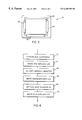
- FIG. 4 is a flow chart of the operation of the printer in FIG. 1 .
- printer link 28 provides for communication to other apparatus, such as an electronic camera that stores digital images.
- Printer link 28 can be a two-connection serial port, an infrared sensor or other standard communication interfaces. An image is received, processed and printed by printer electronics 16 .
- FIG. 2 is an electrical schematic of part of printer electronics 16 and shows the transfer of an image from a data stream to a print.
- Data is received by data receiver 54 , and is operated on by processor 52 .
- Processor 52 stores a received image in memory, 50 .
- Processor 52 transmits the image in memory 50 through display driver 56 to LCD 18 .
- the LCD 18 is driven to present an image to be presented against a pressed photosensitive sheet for contact printing of such image.
- LCD 18 is a monochrome display such as Sharp Corp. model LM64P101.
- Display 18 has 640 horizontal square pixels in 480 vertical lines on 0.23 millimeter spacing to form a display having a 7.43 inch diagonal.
- This LCD display is currently used to display black and white data.
- data are loaded in parallel units of 8 bits that represent on and off conditions for each pixel.
- the display is written in 38,400 8 bit words in 11.7 milliseconds.
- Data can be written to the display by a method set forth in above identified co-pending U.S. patent application Ser. No. 08/824,694.
- Data for a given color plane are written 256 times, each time representing an increased exposure time. At the end of the 256 times, a continuous tone color plane will be written from the source image data.
- LCD display 18 is sequentially illuminated by one of three separate lamps; red fluorescent lamp 20 , green fluorescent lamp 22 and blue fluorescent lamp 24 which are disposed around integrating bar 26 .
- the fluorescent lamps are individually and sequentially actuated by processor 52 for each color plane.
- One integrating bar 26 can be used for all three lamps 20 , 22 , and 24 if the lamps are disposed around three of the sides of integrating bar 26 as shown in FIG. 3 .
- Each lamp is oriented to emit a specific color of light into integrating bar 26 .
- Fluorescent lamps 20 , 22 and 24 are conventional fluorescent lamps using an ultra-violet (254 nm) glow discharge from an excited mercury vapor. Phosphor coatings on the inside of the lamps support phosphors that emit in one of the three primary colors red, green and blue.
- Lamp 20 emits red fluorescent light and can be Harison lamp HMB4-150B, doped with the “R” phosphor. Such a lamp is 4.1 mm in diameter, 150 mm long and emits 8000 candela/m 2 .
- Lamp 22 has the same part number and dimensions but is coated with “G” phosphors to emit green light.
- lamp 24 is the same mechanical package and part number, but coated with the “B” phosphor to emit blue light.
- Using phosphors dedicated to a single color in each lamp permits the energy delivered to a lamp to be concentrated on the emission of a single color required for a given printed color plane of the image.
- Using multiple lamps for each color as in U.S. Pat. No. 5,337,068 requires many more lamps, and more energy will be used than using a unitary lamp for each color. If one or more white light lamps are used, 2 ⁇ 3 of the energy is wasted by filtering out the other two colors.
- Energizing three separate lamps at separate times for each of three separate color planes reduces power requirements and provides sufficient illumination to permit the development of a portable, battery powered printer.
- the processor 52 drives the LCD 18 and sequentially controls the colored light sources for causing three separate color images to be presented against a pressed photosensitive sheet 42 for contact printing of such image.
- FIG. 4 is a flow chart of the process that is used to create a print according to the present invention.
- processor 52 turns on red fluorescent lamp 20 .
- processor 52 writes red image data to liquid crystal display 18 from memory 50 .
- processor switches illumination power to green fluorescent lamp 22 .
- step four, 66 processor loads green data into liquid crystal display 18 from memory 50 .
- step 5 , 68 processor 52 switches illumination power to blue fluorescent lamp 24 .
- step six, 70 processor 52 writes blue image data to liquid crystal display 18 .
- the sequential illumination for specific colors reduces peak power demand on the printer.
- Processor 52 writes the color plane associated with the illuminant color to liquid crystal display 18 .
- Printer 12 is provided with a supply structure 39 which contains a stack of photosensitive media sheets 38 to receive the image illuminated on LCD display 18 . These sheets are light sensitive and are loaded into the camera and stored in light sensitive manner as is known in the art. Springs 39 a continuously urge the supply and hence the stack of photosensitive sheets to move such that the top photosensitive sheet 42 of the media sheet stack 38 is pressed against the LCD.
- Photosensitive sheets can be found in current art as instant silver halide sheets or pressure sensitive microencapsulated crushable color particles such as disclosed in U.S. Pat. Nos. 4,768,050; 5,049,902; and 5,122,432. Alternatively, images can be stored on photographic film and then stored and chemically processed at a later time.
- Such displays generate highly collimated beams of light from each pixel of light emitted by LCD 18 .
- the glass substrate to the front of the display is relatively thin, so that the surface of the front of the display is relatively well focused.
- Using a display with relatively large pixels, such as the 0.23 mm pixels on the Sharp display permits the elimination of a focusing optic.
- the image does have some light bleed between adjacent pixels. This is not a problem if the display has a significantly greater resolution than the image being printed. For instance the 640 by 480 pixel resolution of the display is more than suitable for lower resolution images such as a 320 by 240 pixel image.
- pixel size, pixel count, degree of light collimation, and the front cover thickness of LCD 18 can be selected to permit contact printing from the display using lower-resolution images.
- exposed photosensitive sheet 42 is urged by picker 32 using picker drive 34 into processing rollers 40 under the control of printer electronics 16 .
- Processing rollers 40 are driven by roller drive 36 under control of printer electronics 16 and receive urged photosensitive sheet 42 .
- Processing rollers 40 or other means are used to apply pressure to photosensitive sheet 42 to process and stabilize the latent image on the surface of photosensitive sheet 42 .
- a pod of chemicals at the beginning of photosensitive sheet 42 is burst by processing rollers 40 .
- the chemicals are spread across the image of photosensitive sheet 42 as photosensitive sheet 42 passes through processing rollers 40 .
- Said chemicals operate on the latent image to create a permanent colored dye image on photosensitive sheet 42 .
- the rollers apply pressure to micro-beads containing the latent image. Burst micro-beads release dye chemistries onto photosensitive sheet 42 to create a permanent color image.
Landscapes
- Engineering & Computer Science (AREA)
- Multimedia (AREA)
- Signal Processing (AREA)
- Printers Or Recording Devices Using Electromagnetic And Radiation Means (AREA)
Abstract
Description
Claims (5)
Priority Applications (1)
| Application Number | Priority Date | Filing Date | Title |
|---|---|---|---|
| US08/954,797 US6288788B1 (en) | 1997-10-21 | 1997-10-21 | Printer using liquid crystal display for contact printing |
Applications Claiming Priority (1)
| Application Number | Priority Date | Filing Date | Title |
|---|---|---|---|
| US08/954,797 US6288788B1 (en) | 1997-10-21 | 1997-10-21 | Printer using liquid crystal display for contact printing |
Publications (1)
| Publication Number | Publication Date |
|---|---|
| US6288788B1 true US6288788B1 (en) | 2001-09-11 |
Family
ID=25495942
Family Applications (1)
| Application Number | Title | Priority Date | Filing Date |
|---|---|---|---|
| US08/954,797 Expired - Fee Related US6288788B1 (en) | 1997-10-21 | 1997-10-21 | Printer using liquid crystal display for contact printing |
Country Status (1)
| Country | Link |
|---|---|
| US (1) | US6288788B1 (en) |
Cited By (6)
| Publication number | Priority date | Publication date | Assignee | Title |
|---|---|---|---|---|
| US20050187883A1 (en) * | 1999-08-31 | 2005-08-25 | American Express Travel Related Services Company, Inc. | Methods and apparatus for conducting electronic transactions using biometrics |
| US20070290948A1 (en) * | 2002-08-30 | 2007-12-20 | Hitachi, Ltd. | Plasma display apparatus and method of driving a plasma display panel |
| US20090095811A1 (en) * | 2005-07-28 | 2009-04-16 | Samsung Electronics Co., Ltd. | Methods for controlling access to data stored in smart cards and related devices |
| WO2015128838A3 (en) * | 2014-02-27 | 2015-12-17 | Macauley Robert M | Distributed printing social network |
| CN107736008A (en) * | 2015-06-24 | 2018-02-23 | 帕布洛·艾班纳·雷佐拉 | Compact numerical model analysis developing apparatus |
| US10012864B2 (en) | 2015-04-17 | 2018-07-03 | Travis KNIFFIN | Apparatus, system, and method for developing photos from digital images |
Citations (5)
| Publication number | Priority date | Publication date | Assignee | Title |
|---|---|---|---|---|
| US4811089A (en) | 1987-04-23 | 1989-03-07 | The Mead Corporation | High resolution full color exposure device using an electronically generated mask |
| US4935820A (en) | 1988-01-29 | 1990-06-19 | Minnesota Mining And Manufacturing Company | Imaging slow photographic media with liquid crystal shutters |
| US5337068A (en) * | 1989-12-22 | 1994-08-09 | David Sarnoff Research Center, Inc. | Field-sequential display system utilizing a backlit LCD pixel array and method for forming an image |
| US5760882A (en) * | 1996-06-20 | 1998-06-02 | Eastman Kodak Company | Contact printer and method of making a filter for a contact printer |
| US5860036A (en) * | 1997-06-10 | 1999-01-12 | Eastman Kodak Company | Controlling display useable in printers |
-
1997
- 1997-10-21 US US08/954,797 patent/US6288788B1/en not_active Expired - Fee Related
Patent Citations (5)
| Publication number | Priority date | Publication date | Assignee | Title |
|---|---|---|---|---|
| US4811089A (en) | 1987-04-23 | 1989-03-07 | The Mead Corporation | High resolution full color exposure device using an electronically generated mask |
| US4935820A (en) | 1988-01-29 | 1990-06-19 | Minnesota Mining And Manufacturing Company | Imaging slow photographic media with liquid crystal shutters |
| US5337068A (en) * | 1989-12-22 | 1994-08-09 | David Sarnoff Research Center, Inc. | Field-sequential display system utilizing a backlit LCD pixel array and method for forming an image |
| US5760882A (en) * | 1996-06-20 | 1998-06-02 | Eastman Kodak Company | Contact printer and method of making a filter for a contact printer |
| US5860036A (en) * | 1997-06-10 | 1999-01-12 | Eastman Kodak Company | Controlling display useable in printers |
Cited By (8)
| Publication number | Priority date | Publication date | Assignee | Title |
|---|---|---|---|---|
| US20050187883A1 (en) * | 1999-08-31 | 2005-08-25 | American Express Travel Related Services Company, Inc. | Methods and apparatus for conducting electronic transactions using biometrics |
| US20070290948A1 (en) * | 2002-08-30 | 2007-12-20 | Hitachi, Ltd. | Plasma display apparatus and method of driving a plasma display panel |
| US20090095811A1 (en) * | 2005-07-28 | 2009-04-16 | Samsung Electronics Co., Ltd. | Methods for controlling access to data stored in smart cards and related devices |
| US7815110B2 (en) * | 2005-07-28 | 2010-10-19 | Samsung Electronics Co., Ltd. | Methods for controlling access to data stored in smart cards and related devices |
| WO2015128838A3 (en) * | 2014-02-27 | 2015-12-17 | Macauley Robert M | Distributed printing social network |
| US10012864B2 (en) | 2015-04-17 | 2018-07-03 | Travis KNIFFIN | Apparatus, system, and method for developing photos from digital images |
| CN107736008A (en) * | 2015-06-24 | 2018-02-23 | 帕布洛·艾班纳·雷佐拉 | Compact numerical model analysis developing apparatus |
| US10451964B2 (en) * | 2015-06-24 | 2019-10-22 | Pablo IBAÑEZ RAZOLA | Compact hybrid digital-analogue developing machine |
Similar Documents
| Publication | Publication Date | Title |
|---|---|---|
| US5860036A (en) | Controlling display useable in printers | |
| US5953103A (en) | Color printer | |
| US5128773A (en) | Compact video printer employing a liquid crystal panel | |
| JPH11231278A (en) | Projection type display | |
| US4816846A (en) | Method and apparatus for direct color printing | |
| JP2002207258A (en) | Method and apparatus for printing image with plural formats by using space optical modulator | |
| US6288788B1 (en) | Printer using liquid crystal display for contact printing | |
| US6016157A (en) | Printer using multiple light sources and monochrome LCD | |
| US5214457A (en) | Reflective overhead projector with light-to-light converter | |
| US5970215A (en) | Printing variable density pixels on a photosensitive medium | |
| US5982407A (en) | Color printer | |
| US5949469A (en) | Fluorescent light source for liquid crystal display printing | |
| US6734889B2 (en) | Color printer comprising a linear grating spatial light modulator | |
| US6862108B2 (en) | Optical printer with micromirror device | |
| JPH05165108A (en) | Color printer and fluorescent writing device | |
| US5835809A (en) | Filter for correcting for fluorescent light in color printing | |
| JP2525740B2 (en) | Image capture device | |
| JPH11242298A (en) | Printing device | |
| US20070153080A1 (en) | High-speed continuous film writer | |
| US6788327B2 (en) | Transfer apparatus | |
| EP0512924A2 (en) | Optical exposure system for color video printer | |
| US20040070739A1 (en) | Method and apparatus for printing photographs from digital images using existing DPE mini labs | |
| JP2000309124A (en) | Optical printer | |
| US20060256685A1 (en) | Recording system for light-sensitive sheet | |
| EP0516352A2 (en) | Apparatus and method of successively recording information carried by electro-magnetic radiation beam |
Legal Events
| Date | Code | Title | Description |
|---|---|---|---|
| AS | Assignment |
Owner name: EASTMAN KODAK COMPANY, NEW YORK Free format text: ASSIGNMENT OF ASSIGNORS INTEREST;ASSIGNORS:STEPHENSON, STANLEY W.;QUATTRINI, THOMAS J.;REEL/FRAME:008860/0620;SIGNING DATES FROM 19971017 TO 19971020 |
|
| FEPP | Fee payment procedure |
Free format text: PAYOR NUMBER ASSIGNED (ORIGINAL EVENT CODE: ASPN); ENTITY STATUS OF PATENT OWNER: LARGE ENTITY |
|
| FPAY | Fee payment |
Year of fee payment: 4 |
|
| FEPP | Fee payment procedure |
Free format text: PAYER NUMBER DE-ASSIGNED (ORIGINAL EVENT CODE: RMPN); ENTITY STATUS OF PATENT OWNER: LARGE ENTITY Free format text: PAYOR NUMBER ASSIGNED (ORIGINAL EVENT CODE: ASPN); ENTITY STATUS OF PATENT OWNER: LARGE ENTITY |
|
| FPAY | Fee payment |
Year of fee payment: 8 |
|
| AS | Assignment |
Owner name: CITICORP NORTH AMERICA, INC., AS AGENT, NEW YORK Free format text: SECURITY INTEREST;ASSIGNORS:EASTMAN KODAK COMPANY;PAKON, INC.;REEL/FRAME:028201/0420 Effective date: 20120215 |
|
| REMI | Maintenance fee reminder mailed | ||
| LAPS | Lapse for failure to pay maintenance fees | ||
| STCH | Information on status: patent discontinuation |
Free format text: PATENT EXPIRED DUE TO NONPAYMENT OF MAINTENANCE FEES UNDER 37 CFR 1.362 |
|
| FP | Lapsed due to failure to pay maintenance fee |
Effective date: 20130911 |