US6282995B1 - Plier tool having quickly attachable tool members - Google Patents
Plier tool having quickly attachable tool members Download PDFInfo
- Publication number
- US6282995B1 US6282995B1 US09/659,070 US65907000A US6282995B1 US 6282995 B1 US6282995 B1 US 6282995B1 US 65907000 A US65907000 A US 65907000A US 6282995 B1 US6282995 B1 US 6282995B1
- Authority
- US
- United States
- Prior art keywords
- tool
- tube
- shaft
- ball
- receiving
- Prior art date
- Legal status (The legal status is an assumption and is not a legal conclusion. Google has not performed a legal analysis and makes no representation as to the accuracy of the status listed.)
- Expired - Fee Related
Links
- 238000010276 construction Methods 0.000 description 1
- 230000002093 peripheral effect Effects 0.000 description 1
Images


Classifications
-
- B—PERFORMING OPERATIONS; TRANSPORTING
- B25—HAND TOOLS; PORTABLE POWER-DRIVEN TOOLS; MANIPULATORS
- B25B—TOOLS OR BENCH DEVICES NOT OTHERWISE PROVIDED FOR, FOR FASTENING, CONNECTING, DISENGAGING OR HOLDING
- B25B7/00—Pliers; Other hand-held gripping tools with jaws on pivoted limbs; Details applicable generally to pivoted-limb hand tools
- B25B7/18—Adjusting means for the operating arms
-
- B—PERFORMING OPERATIONS; TRANSPORTING
- B25—HAND TOOLS; PORTABLE POWER-DRIVEN TOOLS; MANIPULATORS
- B25B—TOOLS OR BENCH DEVICES NOT OTHERWISE PROVIDED FOR, FOR FASTENING, CONNECTING, DISENGAGING OR HOLDING
- B25B7/00—Pliers; Other hand-held gripping tools with jaws on pivoted limbs; Details applicable generally to pivoted-limb hand tools
- B25B7/02—Jaws
- B25B7/04—Jaws adjustable
Definitions
- the present invention has arisen to mitigate and/or obviate the afore-described disadvantages of the conventional plier tools or shear tools.
- the primary objective of the present invention is to provide a plier tool or a shear tool including one or more tool members that may be easily attached onto and disengaged from the tool body and that may be easily replaced with the other tool members.
- a tool comprising a tool body including a pair of handles having a first end rotatably secured together with a tube, the handles each including a pole provided thereon, and one or more tool members each including a pair of levers having an orifice formed in a middle portion of the levers for receiving the tube, the levers of the tool member each including a first end having a tool element provided thereon and each including a second end having an aperture formed therein for receiving the poles of the tool body respectively.
- the tool elements of the tool member may be moved toward and away from each other by the handles.
- the poles and the tube of the tool body may be easily and quickly engaged into the apertures and the orifice of the levers for easily and quickly securing or disengaging either of the tool members from the tool body.
- the tool member includes a hub disposed in the middle portions of the levers and having the orifice formed in the hub for receiving the tube.
- a securing device is further provided for securing the hub of the tool member to the tube of the tool body and includes a hole formed in the tube, a ball received in the hole of the tube, and a forcing device for forcing the ball to engage with the hub of the tool member and to secure the hub to the tube.
- the disengaging device includes a spring engaged with the shaft for biasing the shaft relative to the tube and to disengage the depression of the shaft from the ball.
- the tube includes a chamber formed therein for receiving the spring, the shaft includes a head slidably received in the chamber of the tube and engaged with the spring.
- FIG. 1 is an exploded view of a tool in accordance with the present invention
- FIG. 3 is a partial cross sectional view taken along lines 3 — 3 of FIG. 2;
- FIG. 4 is a partial cross sectional view similar to FIG. 3, in which the tool member is detached from the tool body.
- the tool members 60 each includes a pair of levers 61 having a middle portion pivotally or rotatably secured together with a hub 64 for allowing the levers 61 to be rotated about the hub 64 .
- the hub 64 includes an orifice 67 formed therein for receiving the tube 54 , and includes a recess, or a peripheral recess 641 formed therein and communicating with the orifice 67 thereof for receiving the ball 542 and for securing the tool member 60 to the tool body 50 .
- the levers 61 each includes a tool element 62 formed on one end thereof and each includes an arm 63 provided on the other end thereof.
- the arms 63 each includes an aperture 65 , 66 formed therein for receiving the pole 55 , 56 respectively.
- the spring 71 may bias the shaft 70 to move the depression 701 of the shaft 70 relative to the ball 542 or to disengage the depression 701 of the shaft 70 from the ball 542 and may thus actuate the shaft 70 to force the ball 542 to engage into the recess 641 of the hub 64 of either of the tool members 60 , such that the tool members 60 may be easily and quickly attached or secured onto the tool body 50 .
- the tool members 60 may thus be easily and quickly attached onto and disengaged from the tool body 50 and may be easily and quickly replaced with the other tool members.
- the tool elements 62 of the tool members 60 may thus be moved toward or away from each other by the handles 51 , 52 when the handles 51 , 52 are forced toward each other by the users and are biased away from each other by the spring 53 .
- the tool body 50 provides a tube 54 for pivotally or rotatably securing the handles 51 , 52 together and extended outward of the handles 51 , 52 , and provides a pair of poles 55 , 56 provided on the handles 51 , 52 respectively.
- the tube 54 and the poles 55 , 56 of the tool body 50 may be easily and quickly engaged into the orifice 67 of the hub 64 and the apertures 65 , 66 of either of the tool members 60 for allowing the tool members 60 to be easily and quickly secured onto the tool body 50 .
- None of the prior plier tool bodies provide the tube 54 and the poles 55 , 56 for easily and quickly engaging into the tool members.
Landscapes
- Engineering & Computer Science (AREA)
- Mechanical Engineering (AREA)
- Earth Drilling (AREA)
Abstract
A plier or shear tool includes a pair of handles having one end rotatably secured together with a tube and each having a pole. One or more tool members each includes a pair of levers having a middle orifice for receiving the tube and each having an aperture for receiving the poles and for quickly securing the tool members to the handles. A ball is received in the tube, a shaft is received in the tube and has a depression for receiving the ball. A spring may bias the shaft to disengage the depression from the ball and to force the ball to engage with the hub.
Description
1. Field of the Invention
The present invention relates to a plier tool or a shear tool, and more particularly to a plier tool or a shear tool having one or more tool members that may be easily attached onto and disengaged from the tool body and that may be easily replaced with the other tool members.
2. Description of the Prior Art
U.S. Pat. No. 4,793,224 to Huang, and U.S. Pat. No. 5,826,467 to Huang disclose two typical ring plier tools having a tool member, in which the driving directions of the tool member may be changed by securing different portions of the tool member onto the tool body. However, the other plier tool members or shear members may not be changed or attached onto the tool body, and may not be replaced with each other. In addition, the tool member and the tool body are pivotally or rotatably coupled together with a shaft that may be damaged after use.
The present invention has arisen to mitigate and/or obviate the afore-described disadvantages of the conventional plier tools or shear tools.
The primary objective of the present invention is to provide a plier tool or a shear tool including one or more tool members that may be easily attached onto and disengaged from the tool body and that may be easily replaced with the other tool members.
In accordance with one aspect of the invention, there is provided a tool comprising a tool body including a pair of handles having a first end rotatably secured together with a tube, the handles each including a pole provided thereon, and one or more tool members each including a pair of levers having an orifice formed in a middle portion of the levers for receiving the tube, the levers of the tool member each including a first end having a tool element provided thereon and each including a second end having an aperture formed therein for receiving the poles of the tool body respectively. The tool elements of the tool member may be moved toward and away from each other by the handles. The poles and the tube of the tool body may be easily and quickly engaged into the apertures and the orifice of the levers for easily and quickly securing or disengaging either of the tool members from the tool body.
The tool member includes a hub disposed in the middle portions of the levers and having the orifice formed in the hub for receiving the tube. A securing device is further provided for securing the hub of the tool member to the tube of the tool body and includes a hole formed in the tube, a ball received in the hole of the tube, and a forcing device for forcing the ball to engage with the hub of the tool member and to secure the hub to the tube.
The hub includes a recess formed therein for receiving the ball. The forcing device includes a shaft received in the tube, the shaft includes a depression formed therein for receiving the ball, and the forcing device further includes a device for disengaging the depression of the shaft from the ball.
The disengaging device includes a spring engaged with the shaft for biasing the shaft relative to the tube and to disengage the depression of the shaft from the ball. The tube includes a chamber formed therein for receiving the spring, the shaft includes a head slidably received in the chamber of the tube and engaged with the spring.
Further objectives and advantages of the present invention will become apparent from a careful reading of a detailed description provided hereinbelow, with appropriate reference to accompanying drawings.
FIG. 1 is an exploded view of a tool in accordance with the present invention;
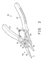
FIG. 2 is a perspective view of the tool;
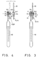
FIG. 3 is a partial cross sectional view taken along lines 3—3 of FIG. 2; and
FIG. 4 is a partial cross sectional view similar to FIG. 3, in which the tool member is detached from the tool body.
Referring to the drawings, and initially to FIGS. 1-3, a tool in accordance with the present invention may be a plier tool or a shear tool or the like, and comprises a tool body 50 and one or more tool members 60 that may be easily and quickly attached onto and disengaged from the tool body 50. The tool body 50 includes a pair of handles 51, 52 having one end pivotally or rotatably secured together with a tube 54. The tube 54 is extended outward of the handles 51, 52 and includes a bore 57 formed therein and includes an hole 541 laterally formed therein and communicating with the bore 57 thereof for receiving a ball 542 therein. The handles 51, 52 each includes a pole 55, 56 extended therefrom and preferably parallel to the tube 54. A spring 53 is engaged between the handles 51, 52 for biasing the handles 51, 52 away from each other.
The tool members 60 each includes a pair of levers 61 having a middle portion pivotally or rotatably secured together with a hub 64 for allowing the levers 61 to be rotated about the hub 64. The hub 64 includes an orifice 67 formed therein for receiving the tube 54, and includes a recess, or a peripheral recess 641 formed therein and communicating with the orifice 67 thereof for receiving the ball 542 and for securing the tool member 60 to the tool body 50. The levers 61 each includes a tool element 62 formed on one end thereof and each includes an arm 63 provided on the other end thereof. The arms 63 each includes an aperture 65, 66 formed therein for receiving the pole 55, 56 respectively.
A fastener shaft 70 is slidably received in the tube 54 and includes a cavity or a curved depression 701 formed therein, particularly formed in the middle portion thereof for receiving the ball 542 (FIG. 4). The tube 54 includes a chamber 58 formed therein (FIG. 3) and having an inner diameter greater than that of the bore 57 of the tube 54 for receiving a head 73 of the shaft 70. A spring 71 is received in the chamber 58 of the tube 54 and is engaged between the tube 54 and the head 71 of the shaft 70 for disengaging the depression 701 of the shaft 70 from the ball 542 and for allowing the shaft 70 to force the ball 542 outward of the tube 54 to engage into the recess 641 of the hub 64 of either of the tool members 60 (FIG. 3). Alternatively, the curved depression 701 of the shaft 70 includes a deeper middle portion for receiving the ball 542 and for allowing the ball 542 to be disengaged from the hub 64 of the tool members 60, and may include two end portions for partially receiving the ball 542 and for partially forcing the ball 542 outward of the tube 54 to engage with the hub 64 of the tool members
In operation, as shown in FIG. 4, when the shaft 70 is forced inward of the tube 54 against the spring 71 in order to align the depression 701 of the shaft 70 with the ball 542, the ball 542 may be received in the depression 701 of the shaft 70 and may thus be disengaged from the recess 641 of the hub 64 of either of the tool members 60, such that the tool members 60 may be easily and quickly disengaged from the tool body 50. At this moment, the tube 54 and the poles 55, 56 of the tool body 50 may be easily and quickly engaged into the orifice 67 of the hub 64 and the apertures 65, 66 of either of the tool members 60. When the shaft 70 is released, the spring 71 may bias the shaft 70 to move the depression 701 of the shaft 70 relative to the ball 542 or to disengage the depression 701 of the shaft 70 from the ball 542 and may thus actuate the shaft 70 to force the ball 542 to engage into the recess 641 of the hub 64 of either of the tool members 60, such that the tool members 60 may be easily and quickly attached or secured onto the tool body 50. The tool members 60 may thus be easily and quickly attached onto and disengaged from the tool body 50 and may be easily and quickly replaced with the other tool members. The tool elements 62 of the tool members 60 may thus be moved toward or away from each other by the handles 51, 52 when the handles 51, 52 are forced toward each other by the users and are biased away from each other by the spring 53.
It is to be noted that the tool body 50 provides a tube 54 for pivotally or rotatably securing the handles 51, 52 together and extended outward of the handles 51, 52, and provides a pair of poles 55, 56 provided on the handles 51, 52 respectively. The tube 54 and the poles 55, 56 of the tool body 50 may be easily and quickly engaged into the orifice 67 of the hub 64 and the apertures 65, 66 of either of the tool members 60 for allowing the tool members 60 to be easily and quickly secured onto the tool body 50. None of the prior plier tool bodies provide the tube 54 and the poles 55, 56 for easily and quickly engaging into the tool members. The tool members 60 may be rotatably engaged onto the tube 54 of the tool body 50 instead of being directly engaged onto the shaft 70 such that the shaft 70 will not be damaged by the tool members 60. The shaft 70 is slidably engaged in the tube 54 and may be used for quickly releasing and securing the tool member 60 to the tool body 50. The tube 54 may also be force-fitted in the hub 64 without the fastener shaft 70. The middle portions of the levers 61 of the tool members 60 may include the orifice 67 directly formed therein, without the hub 64, for rotatably receiving the tube 54 and for allowing the levers 61 to be rotatably secured together with the tube 54.
Accordingly, the tool in accordance with the present invention, particularly the plier tool or the shear tool includes one or more tool members that may be easily attached onto and disengaged from the tool body and that may be easily replaced with the other tool members.
Although this invention has been described with a certain degree of particularity, it is to be understood that the present disclosure has been made by way of example only and that numerous changes in the detailed construction and the combination and arrangement of parts may be resorted to without departing from the spirit and scope of the invention as hereinafter claimed.
Claims (5)
1. A tool comprising:
a tool body including a pair of handles having a first end rotatably secured together with a tube, said handles each including a pole provided thereon,
a first tool member including a pair of levers having an orifice formed in a middle portion of said levers for receiving said tube, said levers of said first tool member each including a first end having a tool element provided thereon and each including a second end having an aperture formed therein for receiving said poles of said tool body respectively, said first tool member including a hub disposed in said middle portions of said levers and having said orifice formed in said hub for receiving said tube,
means for securing said hub of said first tool member to said tube of said tool body, said securing means including a hole formed in said tube, a ball received in said hole of said tube, and means for forcing said ball to engage with said hub and to secure said hub to said tube,
said tool elements of said first tool member being allowed to be moved toward and away from each other by said handles.
2. The tool according to claim 1, wherein said hub includes a recess formed therein for receiving said ball.
3. The tool according to claim 1, wherein said forcing means includes a shaft received in said tube, said shaft includes a depression formed therein for receiving said ball, and said forcing means further includes means for disengaging said depression of said shaft from said ball.
4. The tool according to claim 3, wherein said disengaging means includes a spring engaged with said shaft for biasing said shaft relative to said tube and to disengage said depression of said shaft from said ball.
5. The tool according to claim 4, wherein said tube includes a chamber formed therein for receiving said spring, said shaft includes a head slidably received in said chamber of said tube and engaged with said spring.
Priority Applications (1)
| Application Number | Priority Date | Filing Date | Title |
|---|---|---|---|
| US09/659,070 US6282995B1 (en) | 2000-09-11 | 2000-09-11 | Plier tool having quickly attachable tool members |
Applications Claiming Priority (1)
| Application Number | Priority Date | Filing Date | Title |
|---|---|---|---|
| US09/659,070 US6282995B1 (en) | 2000-09-11 | 2000-09-11 | Plier tool having quickly attachable tool members |
Publications (1)
| Publication Number | Publication Date |
|---|---|
| US6282995B1 true US6282995B1 (en) | 2001-09-04 |
Family
ID=24643904
Family Applications (1)
| Application Number | Title | Priority Date | Filing Date |
|---|---|---|---|
| US09/659,070 Expired - Fee Related US6282995B1 (en) | 2000-09-11 | 2000-09-11 | Plier tool having quickly attachable tool members |
Country Status (1)
| Country | Link |
|---|---|
| US (1) | US6282995B1 (en) |
Cited By (34)
| Publication number | Priority date | Publication date | Assignee | Title |
|---|---|---|---|---|
| US6647835B1 (en) * | 2002-10-17 | 2003-11-18 | Awi Acquisition Company | Pliers with replaceable jaws |
| US20040000058A1 (en) * | 2002-07-01 | 2004-01-01 | Shyr Hway Jeng | Tool device having changeable tool members |
| US20040221695A1 (en) * | 2003-05-08 | 2004-11-11 | Chih-Ching Hsien | Pliers |
| US6983506B1 (en) * | 2001-11-20 | 2006-01-10 | Coffee Brown | Universal, interchangeable tool attachment system |
| US7055413B1 (en) * | 2005-03-08 | 2006-06-06 | Tien-Shui Wang | Pair of pliers for snap rings |
| US20060161182A1 (en) * | 2005-01-19 | 2006-07-20 | Applied Medical Resources Corporation | Single fire vascular clip applier with disposable jaw |
| US20060253995A1 (en) * | 1999-01-29 | 2006-11-16 | Leatherman Tool Group, Inc. | Multipurpose locking pliers |
| USD548555S1 (en) * | 2005-10-12 | 2007-08-14 | Shakespeare Company, Llc | Buoyant metallic pliers |
| US20070221016A1 (en) * | 2006-03-21 | 2007-09-27 | Xtools, Llc | Buoyant metal composite pliers |
| US7353736B2 (en) * | 2005-07-27 | 2008-04-08 | Leatherman Tool Group, Inc. | Enhanced multi-function hand tool |
| US20080248446A1 (en) * | 2007-04-09 | 2008-10-09 | Zbigniew Pona | Ultrasonic crown and bridge remover |
| US20090113721A1 (en) * | 2007-11-02 | 2009-05-07 | Glenn Robinson | Clamping and cutting apparatus with interchangeable heads |
| US20090320300A1 (en) * | 2008-06-25 | 2009-12-31 | Success & Tech Industrial Co. ,Ltd. | Pruning shears |
| US20100037470A1 (en) * | 2008-06-25 | 2010-02-18 | Mei-Chih Liu | Pruning shears |
| US7735399B2 (en) | 2007-07-05 | 2010-06-15 | IBT Holdings, Inc | Clamping and cutting apparatus with adjustable head |
| US20100268254A1 (en) * | 2007-11-12 | 2010-10-21 | Joe Alan Golden | Clamp System and Method of Using the Same |
| US20110107534A1 (en) * | 2009-10-19 | 2011-05-12 | Michael Eugene Hoctor | Broken or clogged aerosol dispenser recovery tool |
| US20110131814A1 (en) * | 2009-12-09 | 2011-06-09 | Midwest Tool And Cutlery Company | Compound leverage hand tool with interchangeable tool head |
| US20120102752A1 (en) * | 2010-11-01 | 2012-05-03 | Steele Michael S | Tube cutter |
| EP2604200A3 (en) * | 2009-05-08 | 2013-08-07 | Breseight Pty Limited | Retooling device and tool |
| US20130247385A1 (en) * | 2012-03-23 | 2013-09-26 | The National Telephone Supply Company | Compound wire rope cutter |
| US20140109731A1 (en) * | 2012-10-19 | 2014-04-24 | Min-Cheng Tseng | Pliers for c-shaped lock rings |
| USD703506S1 (en) * | 2011-11-07 | 2014-04-29 | Rostra Tool Company | Cable preparation tool |
| US8793883B1 (en) * | 2013-03-15 | 2014-08-05 | Galliot, LLC | Clipper |
| US8904647B2 (en) | 2011-11-07 | 2014-12-09 | Rostra Tool Company | Cable preparation tool |
| USD722849S1 (en) * | 2012-12-28 | 2015-02-24 | M & Y Trading Corp. | Tool |
| US20150290778A1 (en) * | 2014-02-25 | 2015-10-15 | Todd Joseph Burns | Expanding Grips |
| US20170113358A1 (en) * | 2015-10-23 | 2017-04-27 | Wezag Gmbh Werkzeugfabrik | Group of Manual Pliers |
| US20190118347A1 (en) * | 2017-10-23 | 2019-04-25 | Min-Zheng Zeng | Replacement structre of pair of pliers |
| USD885154S1 (en) | 2015-05-11 | 2020-05-26 | Todd Joseph Burns | Multifunctional tool with interchangeable head |
| USD890588S1 (en) * | 2018-08-07 | 2020-07-21 | Harry Wong | MIG pliers |
| US10973609B2 (en) | 2018-07-25 | 2021-04-13 | Zbigniew Pona | Vibrating crown and bridge remover |
| US10994390B2 (en) | 2018-11-30 | 2021-05-04 | Snap-On Incorporated | Push button pin for pliers |
| US11691249B2 (en) | 2020-07-29 | 2023-07-04 | Snap-On Incorporated | Push button release mechanism for pliers |
Citations (7)
| Publication number | Priority date | Publication date | Assignee | Title |
|---|---|---|---|---|
| US1005661A (en) * | 1909-06-03 | 1911-10-10 | Samuel Thomas Shirt | Hand-shears. |
| US3132550A (en) * | 1962-02-19 | 1964-05-12 | Sion Frederick | Combination stretching and squeezing tool |
| US4793224A (en) | 1987-06-03 | 1988-12-27 | Huang Hsin Teh | Combination retaining ring fitting tool |
| US5327802A (en) * | 1993-05-21 | 1994-07-12 | Yu Chin Yung | Combination pliers |
| US5546661A (en) * | 1995-11-13 | 1996-08-20 | Yang; Chung-Jeng | Gardening shears |
| US5826467A (en) | 1997-04-21 | 1998-10-27 | Huang; Hsin Te | Easy shift snap ring pliers |
| US6009583A (en) * | 1997-11-10 | 2000-01-04 | Swanstrom Tools Usa Inc. | Pliers-knife combination |
-
2000
- 2000-09-11 US US09/659,070 patent/US6282995B1/en not_active Expired - Fee Related
Patent Citations (7)
| Publication number | Priority date | Publication date | Assignee | Title |
|---|---|---|---|---|
| US1005661A (en) * | 1909-06-03 | 1911-10-10 | Samuel Thomas Shirt | Hand-shears. |
| US3132550A (en) * | 1962-02-19 | 1964-05-12 | Sion Frederick | Combination stretching and squeezing tool |
| US4793224A (en) | 1987-06-03 | 1988-12-27 | Huang Hsin Teh | Combination retaining ring fitting tool |
| US5327802A (en) * | 1993-05-21 | 1994-07-12 | Yu Chin Yung | Combination pliers |
| US5546661A (en) * | 1995-11-13 | 1996-08-20 | Yang; Chung-Jeng | Gardening shears |
| US5826467A (en) | 1997-04-21 | 1998-10-27 | Huang; Hsin Te | Easy shift snap ring pliers |
| US6009583A (en) * | 1997-11-10 | 2000-01-04 | Swanstrom Tools Usa Inc. | Pliers-knife combination |
Cited By (49)
| Publication number | Priority date | Publication date | Assignee | Title |
|---|---|---|---|---|
| US7363669B2 (en) * | 1999-01-29 | 2008-04-29 | Leatherman Tool Group, Inc. | Multipurpose locking pliers |
| US20060253995A1 (en) * | 1999-01-29 | 2006-11-16 | Leatherman Tool Group, Inc. | Multipurpose locking pliers |
| US6983506B1 (en) * | 2001-11-20 | 2006-01-10 | Coffee Brown | Universal, interchangeable tool attachment system |
| US20040000058A1 (en) * | 2002-07-01 | 2004-01-01 | Shyr Hway Jeng | Tool device having changeable tool members |
| US6647835B1 (en) * | 2002-10-17 | 2003-11-18 | Awi Acquisition Company | Pliers with replaceable jaws |
| US20040221695A1 (en) * | 2003-05-08 | 2004-11-11 | Chih-Ching Hsien | Pliers |
| US6941846B2 (en) * | 2003-05-08 | 2005-09-13 | Chih-Ching Hsien | Pliers |
| US20060161182A1 (en) * | 2005-01-19 | 2006-07-20 | Applied Medical Resources Corporation | Single fire vascular clip applier with disposable jaw |
| US7842045B2 (en) * | 2005-01-19 | 2010-11-30 | Applied Medical Resources Corporation | Single fire vascular clip applier with disposable jaw |
| US7055413B1 (en) * | 2005-03-08 | 2006-06-06 | Tien-Shui Wang | Pair of pliers for snap rings |
| US7353736B2 (en) * | 2005-07-27 | 2008-04-08 | Leatherman Tool Group, Inc. | Enhanced multi-function hand tool |
| US7921752B2 (en) * | 2005-07-27 | 2011-04-12 | Leatherman Tool Group, Inc. | Enhanced multi-function hand tool |
| US20080201861A1 (en) * | 2005-07-27 | 2008-08-28 | Leatherman Tool Group, Inc. | Enhanced multi-function hand tool |
| USD548555S1 (en) * | 2005-10-12 | 2007-08-14 | Shakespeare Company, Llc | Buoyant metallic pliers |
| US20070221016A1 (en) * | 2006-03-21 | 2007-09-27 | Xtools, Llc | Buoyant metal composite pliers |
| US20080248446A1 (en) * | 2007-04-09 | 2008-10-09 | Zbigniew Pona | Ultrasonic crown and bridge remover |
| US8162661B2 (en) * | 2007-04-09 | 2012-04-24 | Zbigniew Pona | Ultrasonic crown and bridge remover |
| US7735399B2 (en) | 2007-07-05 | 2010-06-15 | IBT Holdings, Inc | Clamping and cutting apparatus with adjustable head |
| US20090113721A1 (en) * | 2007-11-02 | 2009-05-07 | Glenn Robinson | Clamping and cutting apparatus with interchangeable heads |
| US7730811B2 (en) | 2007-11-02 | 2010-06-08 | IBT Holdings, Inc. | Clamping and cutting apparatus with interchangeable heads |
| US20100268254A1 (en) * | 2007-11-12 | 2010-10-21 | Joe Alan Golden | Clamp System and Method of Using the Same |
| US8109003B2 (en) * | 2008-06-25 | 2012-02-07 | Success & Tech Industrial Co., Ltd. | Pruning shears |
| US20100037470A1 (en) * | 2008-06-25 | 2010-02-18 | Mei-Chih Liu | Pruning shears |
| US20090320300A1 (en) * | 2008-06-25 | 2009-12-31 | Success & Tech Industrial Co. ,Ltd. | Pruning shears |
| EP2604200A3 (en) * | 2009-05-08 | 2013-08-07 | Breseight Pty Limited | Retooling device and tool |
| EP2427302A4 (en) * | 2009-05-08 | 2013-08-07 | Breseight Pty Ltd | Retooling device and tool |
| AU2010244982B2 (en) * | 2009-05-08 | 2016-03-24 | Breseight Pty Limited | Retooling device and tool |
| US20110107534A1 (en) * | 2009-10-19 | 2011-05-12 | Michael Eugene Hoctor | Broken or clogged aerosol dispenser recovery tool |
| US20110131814A1 (en) * | 2009-12-09 | 2011-06-09 | Midwest Tool And Cutlery Company | Compound leverage hand tool with interchangeable tool head |
| US8316549B2 (en) * | 2009-12-09 | 2012-11-27 | Midwest Tool And Cutlery Company | Compound leverage hand tool with interchangeable tool head |
| US20120102752A1 (en) * | 2010-11-01 | 2012-05-03 | Steele Michael S | Tube cutter |
| US8904647B2 (en) | 2011-11-07 | 2014-12-09 | Rostra Tool Company | Cable preparation tool |
| USD703506S1 (en) * | 2011-11-07 | 2014-04-29 | Rostra Tool Company | Cable preparation tool |
| US20130247385A1 (en) * | 2012-03-23 | 2013-09-26 | The National Telephone Supply Company | Compound wire rope cutter |
| US20140109731A1 (en) * | 2012-10-19 | 2014-04-24 | Min-Cheng Tseng | Pliers for c-shaped lock rings |
| US8919227B2 (en) * | 2012-10-19 | 2014-12-30 | Min-Cheng Tseng | Pliers for C-shaped lock rings |
| USD722849S1 (en) * | 2012-12-28 | 2015-02-24 | M & Y Trading Corp. | Tool |
| US9854747B2 (en) | 2013-03-15 | 2018-01-02 | Galliot, LLC | Clipper |
| US8793883B1 (en) * | 2013-03-15 | 2014-08-05 | Galliot, LLC | Clipper |
| US20150290778A1 (en) * | 2014-02-25 | 2015-10-15 | Todd Joseph Burns | Expanding Grips |
| USD885154S1 (en) | 2015-05-11 | 2020-05-26 | Todd Joseph Burns | Multifunctional tool with interchangeable head |
| US20170113358A1 (en) * | 2015-10-23 | 2017-04-27 | Wezag Gmbh Werkzeugfabrik | Group of Manual Pliers |
| EP3159107B1 (en) * | 2015-10-23 | 2020-05-06 | Wezag GmbH Werkzeugfabrik | Group of hand pliers |
| US11794361B2 (en) | 2015-10-23 | 2023-10-24 | Wezag Gmbh & Co. Kg | Group of manual pliers |
| US20190118347A1 (en) * | 2017-10-23 | 2019-04-25 | Min-Zheng Zeng | Replacement structre of pair of pliers |
| US10973609B2 (en) | 2018-07-25 | 2021-04-13 | Zbigniew Pona | Vibrating crown and bridge remover |
| USD890588S1 (en) * | 2018-08-07 | 2020-07-21 | Harry Wong | MIG pliers |
| US10994390B2 (en) | 2018-11-30 | 2021-05-04 | Snap-On Incorporated | Push button pin for pliers |
| US11691249B2 (en) | 2020-07-29 | 2023-07-04 | Snap-On Incorporated | Push button release mechanism for pliers |
Similar Documents
| Publication | Publication Date | Title |
|---|---|---|
| US6282995B1 (en) | Plier tool having quickly attachable tool members | |
| US6755423B2 (en) | Tool coupling device for changeable tool members | |
| US6108845A (en) | Tool combination having detachable handle | |
| US5943925A (en) | Tool having a foldable structure | |
| US6877404B2 (en) | Multi-joint wrench | |
| US6546633B1 (en) | Reciprocating saw holder | |
| US5996452A (en) | Chuck device for power tool | |
| US20060145431A1 (en) | Tool connecting device | |
| US6386070B1 (en) | Connecting structure for a hammerhead and a grip | |
| US20080216616A1 (en) | Hand tool with bit release device | |
| US6560913B1 (en) | Device for hooking, measuring, weighing fish | |
| US6336387B1 (en) | Plier device having an easily assembling structure | |
| US20040211300A1 (en) | Extension apparatus between tool and tool bit | |
| US6450067B1 (en) | Ratchet driving tool | |
| US20040126182A1 (en) | Connector | |
| US6530297B2 (en) | Speed wrench having a stable biasing structure | |
| US6116123A (en) | Screw driver having a retractable and rotatable handle | |
| US7066055B1 (en) | Ratchet wrench that can release socket rapidly | |
| US6976411B1 (en) | Extension tool having anchoring device | |
| US20040188957A1 (en) | Insertable tool connector | |
| US6755100B1 (en) | Tool having quick release and positive locking device | |
| US6427561B1 (en) | Strap wrench for driving tubular members | |
| US6059083A (en) | Ratchet mechanism | |
| US6886434B2 (en) | Wrench with a fixed maximum operational torque | |
| US20040045416A1 (en) | Hand tool |
Legal Events
| Date | Code | Title | Description |
|---|---|---|---|
| REMI | Maintenance fee reminder mailed | ||
| LAPS | Lapse for failure to pay maintenance fees | ||
| STCH | Information on status: patent discontinuation |
Free format text: PATENT EXPIRED DUE TO NONPAYMENT OF MAINTENANCE FEES UNDER 37 CFR 1.362 |
|
| FP | Lapsed due to failure to pay maintenance fee |
Effective date: 20050904 |