US6273152B1 - Exact dose dispenser device assembly - Google Patents
Exact dose dispenser device assembly Download PDFInfo
- Publication number
- US6273152B1 US6273152B1 US09/408,832 US40883299A US6273152B1 US 6273152 B1 US6273152 B1 US 6273152B1 US 40883299 A US40883299 A US 40883299A US 6273152 B1 US6273152 B1 US 6273152B1
- Authority
- US
- United States
- Prior art keywords
- barrel
- plunger
- container
- cap
- stop sleeve
- Prior art date
- Legal status (The legal status is an assumption and is not a legal conclusion. Google has not performed a legal analysis and makes no representation as to the accuracy of the status listed.)
- Expired - Fee Related
Links
Images


Classifications
-
- A—HUMAN NECESSITIES
- A61—MEDICAL OR VETERINARY SCIENCE; HYGIENE
- A61M—DEVICES FOR INTRODUCING MEDIA INTO, OR ONTO, THE BODY; DEVICES FOR TRANSDUCING BODY MEDIA OR FOR TAKING MEDIA FROM THE BODY; DEVICES FOR PRODUCING OR ENDING SLEEP OR STUPOR
- A61M5/00—Devices for bringing media into the body in a subcutaneous, intra-vascular or intramuscular way; Accessories therefor, e.g. filling or cleaning devices, arm-rests
- A61M5/178—Syringes
- A61M5/1782—Devices aiding filling of syringes in situ
-
- B—PERFORMING OPERATIONS; TRANSPORTING
- B01—PHYSICAL OR CHEMICAL PROCESSES OR APPARATUS IN GENERAL
- B01L—CHEMICAL OR PHYSICAL LABORATORY APPARATUS FOR GENERAL USE
- B01L3/00—Containers or dishes for laboratory use, e.g. laboratory glassware; Droppers
- B01L3/02—Burettes; Pipettes
- B01L3/0282—Burettes; Pipettes mounted within a receptacle
-
- A—HUMAN NECESSITIES
- A61—MEDICAL OR VETERINARY SCIENCE; HYGIENE
- A61J—CONTAINERS SPECIALLY ADAPTED FOR MEDICAL OR PHARMACEUTICAL PURPOSES; DEVICES OR METHODS SPECIALLY ADAPTED FOR BRINGING PHARMACEUTICAL PRODUCTS INTO PARTICULAR PHYSICAL OR ADMINISTERING FORMS; DEVICES FOR ADMINISTERING FOOD OR MEDICINES ORALLY; BABY COMFORTERS; DEVICES FOR RECEIVING SPITTLE
- A61J1/00—Containers specially adapted for medical or pharmaceutical purposes
- A61J1/14—Details; Accessories therefor
- A61J1/20—Arrangements for transferring or mixing fluids, e.g. from vial to syringe
- A61J1/2003—Accessories used in combination with means for transfer or mixing of fluids, e.g. for activating fluid flow, separating fluids, filtering fluid or venting
- A61J1/2048—Connecting means
- A61J1/2055—Connecting means having gripping means
-
- A—HUMAN NECESSITIES
- A61—MEDICAL OR VETERINARY SCIENCE; HYGIENE
- A61J—CONTAINERS SPECIALLY ADAPTED FOR MEDICAL OR PHARMACEUTICAL PURPOSES; DEVICES OR METHODS SPECIALLY ADAPTED FOR BRINGING PHARMACEUTICAL PRODUCTS INTO PARTICULAR PHYSICAL OR ADMINISTERING FORMS; DEVICES FOR ADMINISTERING FOOD OR MEDICINES ORALLY; BABY COMFORTERS; DEVICES FOR RECEIVING SPITTLE
- A61J1/00—Containers specially adapted for medical or pharmaceutical purposes
- A61J1/14—Details; Accessories therefor
- A61J1/20—Arrangements for transferring or mixing fluids, e.g. from vial to syringe
- A61J1/2096—Combination of a vial and a syringe for transferring or mixing their contents
-
- A—HUMAN NECESSITIES
- A61—MEDICAL OR VETERINARY SCIENCE; HYGIENE
- A61M—DEVICES FOR INTRODUCING MEDIA INTO, OR ONTO, THE BODY; DEVICES FOR TRANSDUCING BODY MEDIA OR FOR TAKING MEDIA FROM THE BODY; DEVICES FOR PRODUCING OR ENDING SLEEP OR STUPOR
- A61M5/00—Devices for bringing media into the body in a subcutaneous, intra-vascular or intramuscular way; Accessories therefor, e.g. filling or cleaning devices, arm-rests
- A61M5/178—Syringes
- A61M5/31—Details
- A61M5/315—Pistons; Piston-rods; Guiding, blocking or restricting the movement of the rod or piston; Appliances on the rod for facilitating dosing ; Dosing mechanisms
- A61M5/31533—Dosing mechanisms, i.e. setting a dose
- A61M5/31545—Setting modes for dosing
- A61M5/31548—Mechanically operated dose setting member
- A61M5/3155—Mechanically operated dose setting member by rotational movement of dose setting member, e.g. during setting or filling of a syringe
- A61M5/31553—Mechanically operated dose setting member by rotational movement of dose setting member, e.g. during setting or filling of a syringe without axial movement of dose setting member
-
- A—HUMAN NECESSITIES
- A61—MEDICAL OR VETERINARY SCIENCE; HYGIENE
- A61M—DEVICES FOR INTRODUCING MEDIA INTO, OR ONTO, THE BODY; DEVICES FOR TRANSDUCING BODY MEDIA OR FOR TAKING MEDIA FROM THE BODY; DEVICES FOR PRODUCING OR ENDING SLEEP OR STUPOR
- A61M5/00—Devices for bringing media into the body in a subcutaneous, intra-vascular or intramuscular way; Accessories therefor, e.g. filling or cleaning devices, arm-rests
- A61M5/178—Syringes
- A61M5/31—Details
- A61M5/315—Pistons; Piston-rods; Guiding, blocking or restricting the movement of the rod or piston; Appliances on the rod for facilitating dosing ; Dosing mechanisms
- A61M5/31533—Dosing mechanisms, i.e. setting a dose
- A61M5/31545—Setting modes for dosing
- A61M5/31548—Mechanically operated dose setting member
- A61M5/3156—Mechanically operated dose setting member using volume steps only adjustable in discrete intervals, i.e. individually distinct intervals
-
- A—HUMAN NECESSITIES
- A61—MEDICAL OR VETERINARY SCIENCE; HYGIENE
- A61M—DEVICES FOR INTRODUCING MEDIA INTO, OR ONTO, THE BODY; DEVICES FOR TRANSDUCING BODY MEDIA OR FOR TAKING MEDIA FROM THE BODY; DEVICES FOR PRODUCING OR ENDING SLEEP OR STUPOR
- A61M5/00—Devices for bringing media into the body in a subcutaneous, intra-vascular or intramuscular way; Accessories therefor, e.g. filling or cleaning devices, arm-rests
- A61M5/178—Syringes
- A61M5/31—Details
- A61M5/315—Pistons; Piston-rods; Guiding, blocking or restricting the movement of the rod or piston; Appliances on the rod for facilitating dosing ; Dosing mechanisms
- A61M5/31533—Dosing mechanisms, i.e. setting a dose
- A61M5/31545—Setting modes for dosing
- A61M5/31548—Mechanically operated dose setting member
- A61M5/31563—Mechanically operated dose setting member interacting with a displaceable stop member
-
- A—HUMAN NECESSITIES
- A61—MEDICAL OR VETERINARY SCIENCE; HYGIENE
- A61M—DEVICES FOR INTRODUCING MEDIA INTO, OR ONTO, THE BODY; DEVICES FOR TRANSDUCING BODY MEDIA OR FOR TAKING MEDIA FROM THE BODY; DEVICES FOR PRODUCING OR ENDING SLEEP OR STUPOR
- A61M5/00—Devices for bringing media into the body in a subcutaneous, intra-vascular or intramuscular way; Accessories therefor, e.g. filling or cleaning devices, arm-rests
- A61M5/178—Syringes
- A61M5/31—Details
- A61M5/315—Pistons; Piston-rods; Guiding, blocking or restricting the movement of the rod or piston; Appliances on the rod for facilitating dosing ; Dosing mechanisms
- A61M5/31565—Administration mechanisms, i.e. constructional features, modes of administering a dose
- A61M5/31576—Constructional features or modes of drive mechanisms for piston rods
- A61M5/31578—Constructional features or modes of drive mechanisms for piston rods based on axial translation, i.e. components directly operatively associated and axially moved with plunger rod
- A61M5/3158—Constructional features or modes of drive mechanisms for piston rods based on axial translation, i.e. components directly operatively associated and axially moved with plunger rod performed by axially moving actuator operated by user, e.g. an injection button
-
- A—HUMAN NECESSITIES
- A61—MEDICAL OR VETERINARY SCIENCE; HYGIENE
- A61M—DEVICES FOR INTRODUCING MEDIA INTO, OR ONTO, THE BODY; DEVICES FOR TRANSDUCING BODY MEDIA OR FOR TAKING MEDIA FROM THE BODY; DEVICES FOR PRODUCING OR ENDING SLEEP OR STUPOR
- A61M5/00—Devices for bringing media into the body in a subcutaneous, intra-vascular or intramuscular way; Accessories therefor, e.g. filling or cleaning devices, arm-rests
- A61M5/178—Syringes
- A61M5/31—Details
- A61M5/315—Pistons; Piston-rods; Guiding, blocking or restricting the movement of the rod or piston; Appliances on the rod for facilitating dosing ; Dosing mechanisms
- A61M5/31565—Administration mechanisms, i.e. constructional features, modes of administering a dose
- A61M5/3159—Dose expelling manners
- A61M5/31591—Single dose, i.e. individually set dose administered only once from the same medicament reservoir, e.g. including single stroke limiting means
Definitions
- variable dosage cap has been satisfactory for its intended purpose, it has been characterized by certain disadvantages, particularly in the cost to manufacture the multi-component system, and the necessity of controlling the vacuum created in the bulb for drawings desired dosage into the pipette connected to the bulb.
- the exact dose dispenser of the present invention has been devised, which is relatively inexpensive to manufacture, is easily adjustable for dispensing an exact desired dosage and includes a child resistant closure.
- a variable dosage cap-mounted dropper is disclosed in Foyil U.S. Pat. No. 5,154,702, wherein an overcap housing contains a plunger for compressing a conventional closure-mounted bulb a predetermined distance corresponding to various dosages.
- the exact dose dispenser of the present invention comprises, essentially, a syringe barrel having a plurality of axially extending, circumferentially spaced bosses of different lengths integral with the inner surface of the syringe barrel side wall.
- a plunger is rotatably and slidably mounted in the barrel and is provided with an outwardly extending lug adapted to selectively engage the end of a respective boss when drawing a desired dosage into the syringe barrel.
- the syringe barrel is provided with a child resistant closure having an inner cap and an outer cap.
- the proximate end of the barrel is integral with the inner cap which has dosage indicia carried on the top wall thereof viewable through an aperture in the proximate-end portion of the plunger.
- the dosage indicia on the top wall of the inner cap is aligned with a respective boss on the inner surface of the syringe barrel, whereby when drawing an exact dose into the syringe barrel, the plunger is pushed inwardly to the retracted position within the syringe barrel. The plunger is then rotated to a selected dosage as indicated by the indicia on the top wall of the inner cap and viewable through the aperture in the proximate-end portion of the plunger.
- the plunger is then pulled outwardly of the syringe barrel, thereby drawing a volume of medicament into the syringe barrel until the lug on the plunger abuts the end of the respective boss on the inner surface of the syringe barrel.
- An exact desired dosage is now contained in the syringe barrel which is dispensed therein by pushing the syringe plunger inwardly of the syringe barrel.
- FIG. 1 is a perspective view of a first embodiment of exact dose dispenser assembly in accordance with the present invention
- FIG. 2 is a exploded view of a syringe barrel and plunger forming part of the assembly shown in FIG. 1;
- FIG. 3 is a top plan view of the exact dose dispenser assembly of FIG. 1;
- FIG. 4 is an enlarged transverse sectional view showing the parts in position to dispense a first predetermined dosage
- FIG. 5 is a top plan view of the barrel cap portion and an associated inner cap
- FIG. 6 is a transverse sectional view taken on lines 6 , 6 of FIG. 5;
- FIGS. 7 and 8 are elongated transverse sectional views through the plunger and barrel showing the position of the parts to dispense second and third predetermined dosages;
- FIG. 9 is an enlarged schematic plan view showing the barrel in plan view in broken line and the plunger section and associated lug in full line having been rotated to an intermediate groove position between the lands of the barrel section showing the width (L) of the lug to be greater than the distance (S) of the land plan preventing withdrawal of the plunger from the syringe barrel after assembly;
- FIG. 10 is an enlarged fragmentary side elevational view of the plunger including the stop lug
- FIG. 11 is an enlarger isometric view showing another embodiment of the metered syringe assembly of this invention.
- FIG. 12 is a greatly enlarged sectional elevational view taken on the line 12 , 12 of FIG. 11 showing the relative positions of all the component parts of the metered syringe shown in FIG. 11 prior to use;
- FIG. 13 is an enlarged sectional plan view taken on the line 13 , 13 of FIG. 12 showing a detail of the interference fit of the stop lug on the dial plunger and the encompassing barrel;
- FIG. 14 is a greatly enlarged plan view of the dial plunger assembly
- FIG. 15 is a sectional elevational view taken on the line 15 , 15 of FIG. 14;
- FIG. 16 is an enlarged sectional plan view taken on the line 16 , 16 of FIG. 15 showing details of the stop lug on the plunger body;
- FIG. 17 is an enlarged fragmentary isometric view of a portion of the plunger body including the stop lug;
- FIG. 18 is an enlarged plan view of the stop sleeve
- FIG. 19 is a sectional elevational view taken on the line 19 , 19 of FIG. 18;
- FIG. 20 is a right-hand side elevational view of FIG. 19;
- FIG. 21 is a development view of a portion of the stop sleeve barrel
- FIG. 22 is an enlarged plan view of the inner cap and barrel assembly
- FIG. 23 is a sectional elevational view taken on the line 23 , 23 of FIG. 22;
- FIG. 24 is a right hand side elevational view of the inner cap and barrel assembly shown in FIG. 23;
- FIG. 25 is an enlarged plan view of the outer shell cap
- FIG. 26 is a sectional elevational view taken on the line 26 , 26 of FIG. 25;
- FIG. 27 is a right-hand side elevational view of the outer shell cap shown in FIG. 26;
- FIG. 28 is a bottom plan view of FIG. 26;
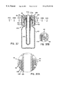
- FIG. 29A is a side elevational view similar to FIG. 12 but showing the metered syringe assembly removed from the medicament container having been actuated to entrain 0.4 mL of medicament;
- FIG. 29B is a side elevational view similar to FIG. 29A but showing the assembly having been actuated to entrain 0.8 ml of medicament.
- FIG. 30 is perspective view of another embodiment of exact dose dispensing assembly in accordance with the present invention.
- FIG. 31 is a perspective view of dial plunger and barrel of the assembly shown in FIG. 30 .
- FIG. 32 is a transverse cross-sectional view of the dial and barrel assembly in the nested position
- FIG. 33 is an enlarged view of the tunnel end of the barrel and plunger shown in broken lines in FIG. 32;
- FIG. 34 is a fragmentary perspective view showing the configuration of the cam follower and the plunger
- FIG. 35 is a perspective view of still another embodiment of exact dose dispenser assembly in accordance with the present invention.
- FIG. 36 is an exploded perspective view showing the components of the assembly including the dial plunger, closure, barrel and container;
- FIG. 37 is a transverse sectional view of the components of the assembly in the assembled position
- FIG. 37 a is a detailed view of the of the assembly shown in FIG. 37;
- FIG. 38 is a transverse sectional view of the outer cap cam follower element
- FIG. 39 is a transverse sectional view of the cap cam follower in a 180° position from that shown in FIG. 38;
- FIGS. 40, 40 a , 40 b and 40 care transverse sectional views taken on lines 40 a — 40 a , 40 b — 40 b and 40 c — 40 c of FIG. 37 respectively showing the cap or outer shell in a locked position in FIG. 40 a and a release position in FIG. 40 b and a ratcheting position in FIG. 40 c.;
- FIG. 40 d is a developed view of the closure or cap and the stop sleeve keyways
- FIG. 41 is a perspective view of still another embodiment of exact dose dispenser assembly in accordance with the present invention.
- FIG. 42 is a perspective exploded view of the plunger element
- FIG. 43 is a transverse sectional view through the plunger assembly
- FIG. 44 is an enlarged view of the tip end of the plunger portion shown in broken lines in FIG. 43;
- FIG. 45 is an exploded view of still another embodiment of exact dose dispenser assembly in accordance with the present invention.
- FIG. 47 is a transverse view taken generally on lines 47 — 47 of FIG. 46;
- FIG. 48 is a transverse section view taken generally on lines 48 — 48 of FIG. 46;
- FIG. 49 is a perspective view of a modified embodiment of exact dose dispenser assembly in accordance with the present invention.
- FIG. 50 is a perspective view of the dial plunger
- FIG. 51 is a transverse sectional view of the dial plunger.
- the exact dose dispenser of the present invention comprises a syringe barrel ( 1 ) having an outlet ( 1 a ) at the distal end there of and a plurality of axially extending, circumferentially-spaced bosses ( 2 ), ( 3 ) and ( 4 ) of different lengths integral with the inner surface of the syringe barrel ( 1 ) sidewall.
- a plunger ( 5 ) having a cruciform configuration is rotatably and slidably mounted in the barrel ( 1 ) and is provided with an outwardly extending lug ( 6 ).
- the dispenser of the present invention is provided with a child resistant closure ( 8 ) for securing the dispenser to a container ( 9 ).
- the child resistant closure ( 8 ) is connected to the proximate end of the barrel ( 1 ) and is of the type disclosed in U.S. Pat. No. 5,316,161, owned by the assignee of the instant application, the disclosure of which being incorporated herein by reference.
- the child resistant closure ( 8 ) includes an inner cap ( 8 a ) integral with the proximate end of the syringe barrel ( 1 ), and having threads ( 8 b ) for securing the closure ( 8 ) to the neck of the container ( 9 ).
- An outer cap ( 8 c ) is rotatably mounted on the inner cap ( 8 a ) and is provided with rigid fingers engageable with cooperating rigid teeth ( 8 e ) provided on the top surface of the top wall of the inner cap ( 8 a ), and additional rigid teeth ( 8 f ) cooperating with flexible fingers ( 8 g ) on the inner cap.
- the inner cap ( 8 a ) is normally biased into engagement with the outer cap ( 8 c ) for screwing the closure ( 8 ) onto the container 9 , but the outer cap ( 8 c ) and inner cap ( 8 a ) become disengaged when the outer cap ( 8 c ) is turned in a direction to remove the closure ( 8 ) from the container resulting in the outer cap ( 8 c ) being freely rotatable on the inner cap ( 8 a ).
- the top wall of the inner cap ( 8 a ) is provided with dosage indicia ( 10 ), ( 11 ) and ( 12 ), such as “1,” 1 ⁇ 2′′ and “1 ⁇ 4′′, aligned with a respective boss ( 2 ), ( 3 ) and ( 4 ) on the inner surface of the syringe barrel ( 1 ).
- dosage indicia ( 10 ), ( 11 ) and ( 12 ) are viewable through an aperture ( 13 ) provided in the proximate-end portion ( 14 ) of the plunger ( 5 ).
- the plunger ( 5 ) is rotated relative to the syringe barrel ( 1 ) until the desired dosage indicia ( 10 ), ( 11 ) or ( 12 ) appears in the aperture or window ( 13 ).
- the plunger( 5 ) is then pulled outwardly of the barrel ( 1 ) to the extended position thereby drawing fluid, such as a medicament, from the container ( 9 ) into the barrel ( 1 ).
- the outer cap ( 8 c ) is pushed downwardly to interconnect the inner and outer caps ( 8 a and 8 c ) so that the closure ( 8 ) and the associated dispenser can be removed from the container ( 9 ) and the exact dosage dispensed from the syringe barrel ( 1 ) by pushing the plunger ( 5 ) inwardly to the retracted position within the barrel ( 1 ).
- the exact dose dispenser of the present invention is relatively inexpensive to manufacture and is easily adjustable for dispensing exact dosages.
- the lug ( 6 ) is triangularly shaped, the long side (S) having a transverse dimension (L) greater than the width of trackways (T) formed in the barrel ( 1 ) so that the plunger is easy to assembly and may not be withdrawn completely from the barrel by reason of the (L) and (S) dimensional relationships. This provides a degree of child resistance or child tamper-proofing for the assembly.
- the lug ( 6 ) has a gently curved periphery as at ( 6 a ) and tapers inwardly slightly as at ( 6 b ) for ease of assembly when initially assembling the plunger in the barrel of the syringe assembly.
- the exact dose dispenser assembly includes an elongated hollow plastic container ( 102 ) for a product such as a medicament and a syringe sub-assembly ( 104 ) mounted in the container ( 102 ) via a retainer cap assembly ( 106 ).
- the syringe assembly ( 104 ) comprises an elongated generally cylindrical hollow barrel ( 110 ) terminating at its outer end in a boss or hub ( 112 ) having a discharge opening ( 114 ) for supporting a syringe needle at the discharge end.
- a cap portion ( 115 ) is integrally formed with the syringe barrel ( 110 ) and serves to detachably mount the barrel of the syringe assembly on the container ( 102 ).
- the cap portion ( 115 ) comprises a generally cylindrical circumferentially extending skirt ( 120 ) having internal spiral threads ( 122 ) which mate with external threads ( 123 ) formed on the neck ( 102 N) of the container ( 102 ).
- the skirt ( 120 ) is connected via a circumferential radially extending connecting wall ( 124 ) to the barrel ( 110 ).
- An inwardly converging frusto-conical sealing lip ( 130 ) depends from the interior of the radial wall ( 124 ). The lip ( 130 ) seals against the axial end face ( 102 t ) of the container ( 102 ) when the syringe assembly ( 104 ) is fully seated on the container ( 102 ).
- a circumferentially raised rim ( 131 ) projects upwardly from the outer periphery of the radial top wall ( 124 ).
- a radially inwardly directed circumferentially extending rib ( 133 ) projects inwardly from the inner surface of the rib ( 131 ) as best illustrated in FIGS. 22 and 24.
- the upper face ( 131 u ) of the rim has a series of scalloped recesses ( 132 ) each having a biased cam surface ( 135 ) for a purpose to be described hereafter.
- the lower edge of the skirt portion ( 120 ) has a series of circumferentially spaced, radially outwardly directed fingers ( 134 ) which likewise have slanted upwardly directed faces ( 136 ) which are slanted in a direction opposite the slant of the cam surfaces ( 132 ).
- the fingers ( 134 ) are connected in spaced relation to the skirt portion ( 120 ) by connecting links ( 136 ) so that the fingers ( 134 ) have a limited flexing movement in an axial direction.
- the barrel ( 110 ), as best illustrated in FIGS. 23 and 24 is of a stepped configuration defining an upper section ( 110 a ) and a lower section ( 110 b ) of smaller diameter connected by a frusto-conical section ( 110 c ).
- a stop sleeve ( 140 ) nests in the enlarged upper portion ( 110 a ) of the barrel.
- 18-21 inclusive, comprises an elongated sleeve portion ( 144 ) having a series of generally rectangular cut-outs ( 146 ) open at the lower terminal end of the sleeve ( 144 ) and defining in the present instance, two stops ( 148 ) and ( 150 ) of different axial heights (H 1 and H 2 ), respectively.
- the side walls of the each cutout ( 146 ) are flared outwardly as at ( 152 and 154 ), respectively to serve as pilot or guide portions when the plunger lug ( 6 ) is in general registry with a selected cutout.
- the upper end of the sleeve ( 140 ) has an upwardly converging frusto-conical wall ( 160 ) terminating in a downwardly depending skirt ( 162 ) defining a circumferentially depending channel ( 164 ) of U-shaped cross-section.
- the skirt ( 162 ) has a radially outwardly directed bead ( 166 ) which snap fits past the bead ( 137 ) of the barrel cap portion ( 110 ) to detachably mount the top sleeve ( 140 ) interiorly of the plunger barrel in the manner shown in FIG. 12 .
- the stop sleeve ( 144 ) is held in place by the inter-engagement of the beads ( 166 and 137 ).
- the top ( 140 t ) of the stop sleeve ( 140 ) as best illustrated in FIGS. 18 and 19 has in the present instance two diametrically opposed raised arcuate segments ( 170 and 172 ), having an arc ⁇ generally equal to the arc (B) of the cutouts ( 186 ) and ( 188 ) to provide visual indicia for the user and aid in the positioning of the plunger lug ( 6 ) in registry with a selected cutout ( 146 ) or ( 148 ) and in turn providing the means for selectively varying the dosage of product drawn into the syringe in a manner to be described in more detail hereafter.
- the exact dose dispenser assembly ( 100 ) further includes a syringe plunger ( 180 ) having a piston ( 182 ) at its outer distal end and an inverted cap ( 184 ) at its outer end.
- the outer periphery of the rim ( 183 ) of the cap is serrated to aid the user in rotating the same.
- the top of the cap ( 184 ) has arcuate slots ( 186 ) and ( 188 ) which are diametrically opposed and of a size and shape to generally conforming to the size and shape of the indicia pads ( 170 ) and ( 172 ) on the stop sleeve ( 140 ).
- the plunger ( 180 ) has a radially projecting lug ( 190 ) located between its outer terminal ends and disposed a distance (D) from the top so that it lies below the lower terminal edge of the stop sleeve ( 140 ) when the plunger ( 180 ) is in a fully seated position as shown in FIG. 12 .
- the exact dose dispenser assembly further includes an outer-shell cap ( 200 ) which as best shown in FIGS. 25-28, inclusively, is generally of cup-like form having an upper skirt portion ( 202 ) and a lower skirt portion ( 204 ) which is stepped outwardly to define a circumferentially extending, downwardly depending face ( 206 ) which has a series of circumferentially spaced inclined cams ( 208 ) which as best illustrated in FIGS. 12 and 29A overlie and are aligned with rim of the top portion of the barrel.
- an outer-shell cap 200
- FIGS. 25-28 inclusively, is generally of cup-like form having an upper skirt portion ( 202 ) and a lower skirt portion ( 204 ) which is stepped outwardly to define a circumferentially extending, downwardly depending face ( 206 ) which has a series of circumferentially spaced inclined cams ( 208 ) which as best illustrated in FIGS. 12 and 29A overlie and are aligned with rim of the
- cams ( 208 ) are inclined relative to the cam faces ( 135 ) so that rotation of the cap ( 200 ) in one direction, a counterclockwise direction, simply produces an override, whereas when the cap is rotated in the opposite direction, the axial locking surfaces ( 210 a ) and ( 135 a ) inter-engage so that the barrel ( 110 ) will rotate with the cap ( 200 ) in a direction to tighten it on the container.
- the underside of the top of the outershell cap ( 200 ) also has a circumferentially extending equi-spaced series of inclined cams ( 210 ) inclined in a direction opposite inclined cams ( 206 ), so that when the outershell cap ( 200 ) is depressed, the inclined cams ( 210 ) can interengage with the scalloped recesses ( 135 ) when the outershell cap ( 200 ) is rotated in the counterclockwise direction to remove the entire syringe subassembly ( 104 ) from the container ( 102 ).
- the lower terminal edge ( 212 ) of the skirt ( 204 ) engages the upper face of the container flange ( 214 c ) to limit downward movement of the outer shell cap ( 200 ) when depressed.
- the container ( 102 ) is first filled with a predetermined quantity of a liquid product.
- the syringe barrel ( 110 ) is then inserted through the open end of the container ( 102 ).
- the barrel ( 110 ) is then rotated in a clockwise direction so that the interengaging threads ( 122 and 123 ) mesh until the barrel cap portion ( 116 ) is fully seated as shown in FIG. 12 .
- the stop sleeve ( 140 ) is inserted into the open end of the barrel ( 110 ) until it bottoms out and the interengaging rims ( 137 and 166 ) are in the position shown in FIG. 12 .
- the top ( 184 ) of the plunger rod ( 180 ) is rotated until the arcuate opening is aligned with the desired quantity to be dispensed, for example, 0.4 ml.
- the plunger ( 180 ) is then actuated axially upwardly. In this position, the lug ( 6 ) is aligned with the cutout and the plunger ( 180 ) can be displaced upwardly until the lug ( 190 ) bottoms on the stop ( 148 ). This is the position shown in FIG. 29 A.
- the container finish includes a circumferentially extending flange ( 214 c ) spaced downwardly from the lower terminal edge of the outer cover at a predetermined distance approximately equal to the displacement distance of the outer cap ( 200 ) relative to the internally threaded mounting head of the barrel.
- the desired quantities can be selectively varied from those indicated in the drawings by simply replacing the stop sleeve ( 140 ) with a stop sleeve ( 140 ) having a different step configuration.
- FIGS. 30-34 there is shown another embodiment of exact dose dispenser assembly in accordance with the present invention.
- This embodiment of the invention has components generally similar to the components of the assembly shown in FIGS. 11 - 29 .
- the elements of the assembly shown in FIGS. 30-34, inclusive are provided with the same reference numeral with an “a” subscript.
- this embodiment of the invention includes a dial plunger ( 180 a ), an outer cap ( 200 a ), a stop sleeve ( 140 a ), a barrel ( 104 a )
- the container is designated by the numeral 102 a .
- the dial plunger ( 180 a ) is an elongated hollow tubular element ( 300 ) having a closed arcuate tip portion ( 302 ) which conforms generally to the internal configuration of the lower end of the barrel surrounding the discharge opening ( 306 ) and designated by the numeral 308 .
- the barrel has a pair of circumferentially extending axially spaced radially outwardly directed sealing ribs ( 310 ) spaced upwardly from the lower terminal end of the plunger dimensioned to provide a sealing engagement with the interior wall of the barrel ( 104 a ) upon activation of the plunger ( 180 a ) axially in the barrel in the manner described previously.
- the stop lug ( 190 a ) has a gently curved outer peripheral surface ( 312 ) to conform generally to the offset in the barrel as shown in FIG. 32 .
- FIGS. 35-40 b inclusive, another embodiment of exact dispenser assembly in accordance with the present invention.
- the assembly which is generally designated by the numeral 100 b includes a plunger ( 180 b ), a barrel ( 104 b ), and container ( 102 b ).
- the outer cap ( 200 b ) and the stop sleeve ( 140 b ) have been integrated and generally designated by the numeral 4100 .
- a single pad is cooperatively associated with the windows.
- the various components of this embodiment of the invention are configured in such a way to provide a squeeze and turn operation which, generally speaking, is easier to manipulate.
- the cap portion ( 200 b ) is of generally cup-like form having an outer circumferentially extending skirt portion ( 402 ), an inner sleeve member ( 404 ) which has internal threads ( 406 ) to mate with threads ( 408 ) on the neck of the container ( 102 b ) to facilitate applying and removing the integrated cap-stop sleeve assembly in the manner described below.
- the outer cap ( 200 b ) has an upstanding central hub portion ( 410 ) which is internally ribbed with a series of circumferentially extending ribs ( 411 ) to mount the barrel ( 104 b ) in the manner shown in FIG. 37 .
- the upper end of the barrel ( 104 b ) has a radially outwardly projecting collar ( 412 ) spaced downwardly from its upper terminal end which has a depending circumferentially extending flexible sealing flange ( 414 ) which seats on the axial end of the container adjacent the discharge opening when the parts are in the assembled relationship shown in FIG. 37 .
- the upper wall of the barrel ( 104 b ) above the collar 412 has external ribs ( 416 ) which engage with the internally ribbed hub ( 410 ) of the cap to support the barrel ( 104 b ) inside the cap portion ( 200 b ) in the manner shown in FIG. 37 .
- the rib arrangement facilitates a press fit and creates a seal between the barrel and outer cap.
- the stop sleeve is formed integrally with the cap portion ( 200 b ) as best shown in FIGS. 37 and 38.
- the stop sleeve ( 140 b ) is formed integrally and is connected to the internally threaded sleeve member ( 404 ) a by short radial connecting wall ( 405 ).
- the plane P-P through the center of the diametrically opposed keyways ( 148 b and 150 b ) which define cam surfaces passes through the dose selector portions ( 438 ) on the outer periphery of the skirt so that when the user aligns the plunger on either of the dose selectors ( 438 ), the cam follower ( 190 b ) is aligned with the keyway cam surfaces ( 148 b and 150 b ) and can be activated by in an axial direction ( 407 ).
- the cam follower is in intermediate positions, it is aligned with and abuts the lower edge of the stop sleeve ( 407 ) to prevent axially upward displacement thereof (see FIG. 29 ).
- the skirt portion ( 402 ) of the cap ( 200 b ) has a pair of diametrically opposed axially extending lugs ( 418 ) which are of a configuration to define a cam surface ( 420 ) and a stop surface ( 422 ).
- the disc portion on the container has diametrically opposed complementary lugs or teeth ( 424 ) which have a tapered cam surface ( 426 ) and a stop surface ( 428 ).
- the teeth ( 424 ) ratchet over the lugs ( 418 ) on the container ( 102 b ) to permit assembly and when rotated in a reverse direction lock to prevent removal of the cap ( 200 b ).
- the skirt portion ( 402 ) is pressed radially inwardly by the user at diametrically opposed points, as at 432 , approximately 90° to the lugs ( 418 ) to permit rotation of the cap ( 200 b ) in a counter-clockwise direction to remove it from the container ( 102 b ).
- the serrations ( 430 ) on the exterior surface of the skirt portion of the cap is interrupted at the squeeze locations ( 432 ) to provide visual indicia to the user.
- the skirt portion part of the cap is also more flexible in these areas for ease of squeezing and removal of the cap.
- the disc-like top ( 434 ) of the plunger has in the present instance, a single indicia in the form of arrow ( 436 ) aligned with an arcuate window ( 438 ), which in turn is aligned with a channel.
- the serrations ( 430 ) on the skirt portion of the cap is also interrupted at two diametrically opposed locations ( 438 ) to provide two dose selectors. Accordingly, when the arrow ( 436 ) on the disc-like top of the plunger is aligned with one of the dose selectors ( 438 ), the user can now withdraw the plunger.
- the cam follower ( 190 b ) is aligned with either the short cam surface ( 148 b ) in FIG. 38 or the extended cam surface ( 150 b ) in FIG. 39 .
- the dose selector sections ( 438 ) on the outer periphery of the skirt portion 432 are aligned with the cam surfaces ( 148 b , 150 b ) in the stop sleeve ( 140 ).
- FIGS. 41-44 inclusive another embodiment of exact dose dispenser assembly in accordance with the present invention, generally similar configuration and operation to the previously described embodiment of FIGS. 35-40 b . Accordingly, similar part numbers have been given the same reference numeral with the subscript “c”.
- the plunger barrel ( 180 a ) is an elongated hollow tubular member open at its lower end to receive a plunger piston ( 502 ) made of a suitable rubber or plastic material.
- the piston ( 502 ) is of a stepped configuration, having a smaller internal piston portion ( 504 ) which engages and seals in the open end of the plunger barrel ( 104 a ) and has a pair of circumferentially extending ribs ( 506 ) providing an interference fit with the internal surface of the plunger barrel ( 180 c ).
- the enlarged piston portion ( 508 ) likewise has radially outwardly projecting circumferentially extending ribs ( 510 ) to engage the interior wall of the barrel ( 104 a ).
- FIGS. 45-48 inclusive another embodiment of exact dose dispenser assembly in accordance with the present invention.
- like elements such as the barrel ( 104 d ) container ( 102 d ) and plunger ( 180 d ) are given the same reference numeral with the subscript “d”.
- This embodiment is generally similar to the embodiment shown and described in FIGS. 41-43, inclusive, which features the integrated cap and stop sleeve arrangement.
- valve ( 602 ) which seats in the open end of the container ( 102 d ) in the manner shown in FIG. 46 .
- the valve ( 602 ) is made of a flexible material, such as a polymeric material, and has a flange portion ( 604 ) at its upper end and a frusto-conical tip portion ( 606 ).
- the frusto-conical tip portion ( 606 ) has a series of slits ( 608 ) extending from the pointed tip ( 610 ) to allow assembly and removal of the plunger barrel and other components in the manner shown in FIG. 46 .
- the valve ( 602 ) functions as a wiper when the barrel and associated elements are withdrawn for a use application to wipe any liquid product on the exterior surface of the barrel.
- FIG. 49 Another embodiment of exact dose dispenser assembly in accordance with the present invention.
- This assembly is generally similar to the previously described assembly in terms of components, function and operation.
- the skirt portion of the cap is provided with figure grip portions ( 702 ) at diametrically opposed locations.
- FIGS. 50 and 51 show a modified dial plunger configuration wherein the disc portion has an opening ( 804 ) in its upper end aligned to accommodate a plug ( 802 ) for an company identification logo or the like.
- the secure dose dispenser assembly of the present invention has many features which may be summarized as follows.
- Secure dose assembly comes as an interval unit, and as part of the package and not as a separate dispenser, that can get disassociated from or lost.
- the syringe style of the present invention allows complete evacuation of all product in the barrel, regardless of product viscosity, ensuring that the product is dispensed in the proper dosage.
- the assembly can be easily and economically manufactured, for example, by standard injection molding of plastic materials such as Polyolefin resins. These materials do not present contact or stability issues which rubber or thermoplastic elastomers may present. Other advantages include little or no chance of mis-dosing to a wiper inserted in the container finish to clean the outside of the barrel upon removal as explained in more detail.
Abstract
Description
Claims (10)
Priority Applications (1)
| Application Number | Priority Date | Filing Date | Title |
|---|---|---|---|
| US09/408,832 US6273152B1 (en) | 1998-09-30 | 1999-09-29 | Exact dose dispenser device assembly |
Applications Claiming Priority (2)
| Application Number | Priority Date | Filing Date | Title |
|---|---|---|---|
| US10243698P | 1998-09-30 | 1998-09-30 | |
| US09/408,832 US6273152B1 (en) | 1998-09-30 | 1999-09-29 | Exact dose dispenser device assembly |
Publications (1)
| Publication Number | Publication Date |
|---|---|
| US6273152B1 true US6273152B1 (en) | 2001-08-14 |
Family
ID=22289835
Family Applications (1)
| Application Number | Title | Priority Date | Filing Date |
|---|---|---|---|
| US09/408,832 Expired - Fee Related US6273152B1 (en) | 1998-09-30 | 1999-09-29 | Exact dose dispenser device assembly |
Country Status (11)
| Country | Link |
|---|---|
| US (1) | US6273152B1 (en) |
| EP (1) | EP1117452A4 (en) |
| JP (1) | JP2002525247A (en) |
| KR (1) | KR20010088828A (en) |
| CN (1) | CN1323229A (en) |
| AU (1) | AU762343B2 (en) |
| BR (1) | BR9914120A (en) |
| CA (1) | CA2345015A1 (en) |
| MX (1) | MXPA01003287A (en) |
| TW (1) | TW418103B (en) |
| WO (1) | WO2000018453A1 (en) |
Cited By (23)
| Publication number | Priority date | Publication date | Assignee | Title |
|---|---|---|---|---|
| US20050070853A1 (en) * | 2003-08-25 | 2005-03-31 | Brian Gatton | Medicament dispensing assembly |
| US20060273061A1 (en) * | 2005-06-06 | 2006-12-07 | Mark Fricke | Method and device for a child resistant dropper closure |
| US20070007302A1 (en) * | 2005-07-08 | 2007-01-11 | Doraiswami Jaichandra | Device for dispensing a controlled dose of a flowable material |
| US20090172870A1 (en) * | 2008-01-09 | 2009-07-09 | Eunha Hong | Compartment Drain Strainer |
| US20090177156A1 (en) * | 2008-01-08 | 2009-07-09 | Rebecca Maclean | Spring driven adjustable oral syringe |
| WO2012061140A1 (en) * | 2010-10-25 | 2012-05-10 | Medrad, Inc. | Bladder syringe fluid delivery system |
| US20120261029A1 (en) * | 2009-10-19 | 2012-10-18 | Yonwoo Co., Ltd. | Liquid dropper allowing quantitative withdrawal, and a cosmetic container equipped with the same |
| WO2013163157A1 (en) * | 2012-04-23 | 2013-10-31 | Medrad, Inc. | Bladder syringe fluid delivery system |
| US8864725B2 (en) | 2009-03-17 | 2014-10-21 | Baxter Corporation Englewood | Hazardous drug handling system, apparatus and method |
| US8899437B2 (en) | 2012-01-20 | 2014-12-02 | Gateway Plastics, Inc. | Closure with integrated dosage cup |
| USD740661S1 (en) | 2012-01-20 | 2015-10-13 | Gateway Plastics, Inc. | Closure with integrated dosage cup |
| US9180252B2 (en) | 2012-04-20 | 2015-11-10 | Bayer Medical Care Inc. | Bellows syringe fluid delivery system |
| USD788315S1 (en) * | 2013-07-24 | 2017-05-30 | Sysmex Corporation | Lid device for analyzer container |
| USD850781S1 (en) * | 2015-10-09 | 2019-06-11 | Medisca Pharmaceutique Inc. | Dispensing container |
| US20200039728A1 (en) * | 2018-08-01 | 2020-02-06 | Veritiv Operating Company | Container assembly with syringe |
| CN111432863A (en) * | 2017-10-17 | 2020-07-17 | 艾迪克斯股份公司 | Manual injection device |
| US10766047B2 (en) | 2016-02-23 | 2020-09-08 | Medisca Pharmaceutique Inc. | Dispensing container and actuator therefor |
| US10875688B1 (en) | 2019-11-25 | 2020-12-29 | Berlin Packaging, Llc | Child resistant senior friendly bottle packaging for liquids |
| US11161657B2 (en) | 2019-11-25 | 2021-11-02 | Berlin Packaging, Llc | Child resistant senior friendly bottle packaging for liquids |
| FR3111339A1 (en) * | 2020-06-11 | 2021-12-17 | L'oreal | Package and distribution of a fluid product, in particular a cosmetic product |
| USD938829S1 (en) | 2018-05-02 | 2021-12-21 | Medisca Pharmaceutique Inc. | Dispensing container |
| US11542075B2 (en) * | 2019-05-28 | 2023-01-03 | Quark Distribution, Inc. | Child resistant bottle closure system |
| USD1012725S1 (en) | 2020-10-07 | 2024-01-30 | Berlin Packaging, Llc | Dosing container |
Families Citing this family (19)
| Publication number | Priority date | Publication date | Assignee | Title |
|---|---|---|---|---|
| KR100592533B1 (en) * | 2002-01-07 | 2006-06-23 | 조순형 | Method and apparatus for the continuous production of foamed metals |
| KR20090041405A (en) * | 2006-08-22 | 2009-04-28 | 메드믹스 시스템즈 아게 | Device and method for storing, mixing and dispensing components |
| DE102007014418A1 (en) * | 2007-03-22 | 2008-09-25 | Eric Schliemann | Method and device for the metered dispensing of a medium |
| US9352354B2 (en) * | 2008-03-24 | 2016-05-31 | Sashco, Inc. | System and method of providing individual quantities of custom colored sealing compound |
| US8834014B2 (en) | 2008-03-24 | 2014-09-16 | Sashco, Inc. | System for providing custom colored sealing compound |
| US8100296B2 (en) | 2008-03-24 | 2012-01-24 | Sashco, Inc. | System and method of providing individual quantities of custom colored sealing compound |
| CA2781483A1 (en) * | 2009-11-20 | 2011-05-26 | Novartis Ag | Syringe |
| ES2502715T3 (en) * | 2010-06-07 | 2014-10-06 | L'oréal | Packaging device and applicator that uses a pipette |
| FR2964953B1 (en) * | 2010-09-17 | 2012-10-26 | Oreal | DEVICE FOR CONDITIONING AND APPLICATION USING A PIPETTE |
| JP2013028373A (en) * | 2011-07-29 | 2013-02-07 | Yoshino Kogyosho Co Ltd | Quantitative cap |
| ES2853323T3 (en) | 2012-04-09 | 2021-09-15 | Becton Dickinson Co | Vial Management Systems and Methods |
| DE102013114336A1 (en) | 2012-12-18 | 2014-06-18 | Slg Pharma Gmbh & Co. Kg | Dosage removable |
| SI2981316T1 (en) * | 2013-04-03 | 2022-10-28 | ARMSTRONG, Sean Terrence | Syringe and an accessory therefor |
| BE1021222B1 (en) | 2014-01-13 | 2015-08-18 | Hubert De Backer Nv | INJECTION SYRINGE WITH CHILD SAFE CAP |
| US10213558B2 (en) * | 2016-03-28 | 2019-02-26 | Glenmark Pharmaceuticals S.A. | Drug delivery device |
| CN107802491A (en) * | 2017-11-21 | 2018-03-16 | 安徽省宿州市第二中学 | A kind of measurable self-suction type liquid medicine bottle |
| CN109677771A (en) * | 2019-01-15 | 2019-04-26 | 中山市华宝勒生活用品实业有限公司 | A kind of reversing dosing container |
| CN110393669A (en) * | 2019-08-20 | 2019-11-01 | 健民药业集团股份有限公司 | A kind of accurate delivery device of children |
| CN117606858A (en) * | 2023-11-01 | 2024-02-27 | 合肥市中心血站 | Device and method for preparing leucocyte extraction sample |
Citations (3)
| Publication number | Priority date | Publication date | Assignee | Title |
|---|---|---|---|---|
| US5746349A (en) * | 1993-07-08 | 1998-05-05 | Janssen Pharmaceutica, N.V. | Childproof dosing device |
| US5836359A (en) * | 1995-06-30 | 1998-11-17 | Concept Workshop Worldwide, Llc | Liquid dosage dispensers |
| US6045003A (en) * | 1995-06-30 | 2000-04-04 | Concept Workshop Worldwide, Llc | Liquid dosage dispensers |
Family Cites Families (4)
| Publication number | Priority date | Publication date | Assignee | Title |
|---|---|---|---|---|
| US5050782A (en) * | 1990-04-18 | 1991-09-24 | Linda J. Wei | Measured volume liquid dispenser having a rotatable plunger with a radial projection for selectively engaging one of a plurality of axial channels formed in the pump cylinder |
| US5154702A (en) * | 1990-05-21 | 1992-10-13 | Wheaton Industries | Variable dosage dropper system |
| CA2129513C (en) * | 1992-02-07 | 1999-12-28 | James L. Drobish | Spray pump package employing multiple orifices for dispensing liquid in different spray patterns with automatically adjusted optimized pump stroke for each pattern |
| US5316161A (en) * | 1993-04-20 | 1994-05-31 | Comar, Inc. | Child resistant closure |
-
1999
- 1999-09-29 CA CA 2345015 patent/CA2345015A1/en not_active Abandoned
- 1999-09-29 CN CN99811495A patent/CN1323229A/en active Pending
- 1999-09-29 WO PCT/US1999/022497 patent/WO2000018453A1/en not_active Application Discontinuation
- 1999-09-29 EP EP99952972A patent/EP1117452A4/en not_active Withdrawn
- 1999-09-29 BR BR9914120A patent/BR9914120A/en not_active IP Right Cessation
- 1999-09-29 KR KR1020017004122A patent/KR20010088828A/en not_active Application Discontinuation
- 1999-09-29 MX MXPA01003287A patent/MXPA01003287A/en unknown
- 1999-09-29 JP JP2000571970A patent/JP2002525247A/en not_active Withdrawn
- 1999-09-29 AU AU65018/99A patent/AU762343B2/en not_active Ceased
- 1999-09-29 US US09/408,832 patent/US6273152B1/en not_active Expired - Fee Related
- 1999-10-12 TW TW88116723A patent/TW418103B/en not_active IP Right Cessation
Patent Citations (3)
| Publication number | Priority date | Publication date | Assignee | Title |
|---|---|---|---|---|
| US5746349A (en) * | 1993-07-08 | 1998-05-05 | Janssen Pharmaceutica, N.V. | Childproof dosing device |
| US5836359A (en) * | 1995-06-30 | 1998-11-17 | Concept Workshop Worldwide, Llc | Liquid dosage dispensers |
| US6045003A (en) * | 1995-06-30 | 2000-04-04 | Concept Workshop Worldwide, Llc | Liquid dosage dispensers |
Cited By (35)
| Publication number | Priority date | Publication date | Assignee | Title |
|---|---|---|---|---|
| US20050070853A1 (en) * | 2003-08-25 | 2005-03-31 | Brian Gatton | Medicament dispensing assembly |
| US20060273061A1 (en) * | 2005-06-06 | 2006-12-07 | Mark Fricke | Method and device for a child resistant dropper closure |
| US20070007302A1 (en) * | 2005-07-08 | 2007-01-11 | Doraiswami Jaichandra | Device for dispensing a controlled dose of a flowable material |
| US7520406B2 (en) | 2005-07-08 | 2009-04-21 | S. C. Johnson & Son, Inc. | Device for dispensing a controlled dose of a flowable material |
| US20090177156A1 (en) * | 2008-01-08 | 2009-07-09 | Rebecca Maclean | Spring driven adjustable oral syringe |
| US8062254B2 (en) | 2008-01-08 | 2011-11-22 | MacLean, LLC | Spring driven adjustable oral syringe |
| US20120101477A1 (en) * | 2008-01-08 | 2012-04-26 | MacLean, LLC | Spring driven adjustable oral syringe |
| US8449499B2 (en) * | 2008-01-08 | 2013-05-28 | MacLean, LLC | Spring driven adjustable oral syringe |
| US20090172870A1 (en) * | 2008-01-09 | 2009-07-09 | Eunha Hong | Compartment Drain Strainer |
| US8864725B2 (en) | 2009-03-17 | 2014-10-21 | Baxter Corporation Englewood | Hazardous drug handling system, apparatus and method |
| US20120261029A1 (en) * | 2009-10-19 | 2012-10-18 | Yonwoo Co., Ltd. | Liquid dropper allowing quantitative withdrawal, and a cosmetic container equipped with the same |
| US9427064B2 (en) * | 2009-10-19 | 2016-08-30 | Yonwoo Co., Ltd | Liquid dropper allowing quantitative withdrawal, and a cosmetic container equipped with the same |
| WO2012061140A1 (en) * | 2010-10-25 | 2012-05-10 | Medrad, Inc. | Bladder syringe fluid delivery system |
| US10835680B2 (en) | 2010-10-25 | 2020-11-17 | Bayer Healthcare Llc | Bladder syringe fluid delivery system |
| US9498570B2 (en) | 2010-10-25 | 2016-11-22 | Bayer Healthcare Llc | Bladder syringe fluid delivery system |
| US10046106B2 (en) | 2010-10-25 | 2018-08-14 | Bayer Healthcare Llc | Bladder syringe fluid delivery system |
| USD740661S1 (en) | 2012-01-20 | 2015-10-13 | Gateway Plastics, Inc. | Closure with integrated dosage cup |
| US8899437B2 (en) | 2012-01-20 | 2014-12-02 | Gateway Plastics, Inc. | Closure with integrated dosage cup |
| US10105491B2 (en) | 2012-04-20 | 2018-10-23 | Bayer Healthcare Llc | Collapsible syringe for fluid delivery system |
| US9180252B2 (en) | 2012-04-20 | 2015-11-10 | Bayer Medical Care Inc. | Bellows syringe fluid delivery system |
| WO2013163157A1 (en) * | 2012-04-23 | 2013-10-31 | Medrad, Inc. | Bladder syringe fluid delivery system |
| USD788315S1 (en) * | 2013-07-24 | 2017-05-30 | Sysmex Corporation | Lid device for analyzer container |
| USD850781S1 (en) * | 2015-10-09 | 2019-06-11 | Medisca Pharmaceutique Inc. | Dispensing container |
| US10766047B2 (en) | 2016-02-23 | 2020-09-08 | Medisca Pharmaceutique Inc. | Dispensing container and actuator therefor |
| CN111432863A (en) * | 2017-10-17 | 2020-07-17 | 艾迪克斯股份公司 | Manual injection device |
| CN111432863B (en) * | 2017-10-17 | 2023-05-30 | 艾迪克斯股份公司 | Manual injection device |
| USD1014283S1 (en) | 2018-05-02 | 2024-02-13 | Medisca Pharmaceutique Inc. | Dispensing container |
| USD938829S1 (en) | 2018-05-02 | 2021-12-21 | Medisca Pharmaceutique Inc. | Dispensing container |
| US10640279B2 (en) * | 2018-08-01 | 2020-05-05 | Veritiv Operating Company | Container assembly with syringe |
| US20200039728A1 (en) * | 2018-08-01 | 2020-02-06 | Veritiv Operating Company | Container assembly with syringe |
| US11542075B2 (en) * | 2019-05-28 | 2023-01-03 | Quark Distribution, Inc. | Child resistant bottle closure system |
| US11161657B2 (en) | 2019-11-25 | 2021-11-02 | Berlin Packaging, Llc | Child resistant senior friendly bottle packaging for liquids |
| US10875688B1 (en) | 2019-11-25 | 2020-12-29 | Berlin Packaging, Llc | Child resistant senior friendly bottle packaging for liquids |
| FR3111339A1 (en) * | 2020-06-11 | 2021-12-17 | L'oreal | Package and distribution of a fluid product, in particular a cosmetic product |
| USD1012725S1 (en) | 2020-10-07 | 2024-01-30 | Berlin Packaging, Llc | Dosing container |
Also Published As
| Publication number | Publication date |
|---|---|
| MXPA01003287A (en) | 2003-03-27 |
| CA2345015A1 (en) | 2000-04-06 |
| JP2002525247A (en) | 2002-08-13 |
| EP1117452A1 (en) | 2001-07-25 |
| WO2000018453A1 (en) | 2000-04-06 |
| AU762343B2 (en) | 2003-06-26 |
| CN1323229A (en) | 2001-11-21 |
| KR20010088828A (en) | 2001-09-28 |
| TW418103B (en) | 2001-01-11 |
| AU6501899A (en) | 2000-04-17 |
| EP1117452A4 (en) | 2002-07-24 |
| WO2000018453A9 (en) | 2000-08-31 |
| BR9914120A (en) | 2001-06-19 |
Similar Documents
| Publication | Publication Date | Title |
|---|---|---|
| US6273152B1 (en) | Exact dose dispenser device assembly | |
| US6315165B1 (en) | Device for expressing substances from a deformable tube | |
| US6770056B2 (en) | Dispensing device | |
| US5497915A (en) | Dispenser pumps | |
| US6655525B2 (en) | Container capable of separately storing and mixing two substances together | |
| JP3029449U (en) | Push-button applicator for applying liquids | |
| US6450352B1 (en) | Child-resistant push and twist locking cap | |
| US4008834A (en) | Tip seal for a dispensing valve | |
| WO2019150106A1 (en) | Improvement to a dosing apparatus and a container | |
| US6899254B1 (en) | Venting seal for dispenser | |
| US7017782B2 (en) | Child resistant safety cap for applicator tubes | |
| CA3066447C (en) | Child resistant container with pump actuator | |
| US20050070853A1 (en) | Medicament dispensing assembly | |
| JP2005041579A (en) | Device for dispensing material from container | |
| US4679714A (en) | Unit dose liquid dispenser | |
| GB2297738A (en) | Milk powder dispenser | |
| US20170015474A1 (en) | Variable Metered Dose Closure | |
| US11116693B2 (en) | Pediatric dosing dispenser | |
| EP1204357B1 (en) | Dispenser for soft flowable materials | |
| WO2000031506A1 (en) | Fluid dispensing device | |
| JP2018177330A (en) | Refill container and application container using the same |
Legal Events
| Date | Code | Title | Description |
|---|---|---|---|
| AS | Assignment |
Owner name: COMAR, INC., NEW JERSEY Free format text: ASSIGNMENT OF ASSIGNORS INTEREST;ASSIGNORS:BUEHLER, JOHN D.;MATHIAS, ERIC S.;REEL/FRAME:010478/0015 Effective date: 19991020 |
|
| AS | Assignment |
Owner name: LASALLE BUSINESS CREDIT, INC., PENNSYLVANIA Free format text: ASSIGNMENT OF ASSIGNORS INTEREST;ASSIGNOR:COMAR, INC.;REEL/FRAME:012641/0610 Effective date: 20020117 |
|
| FPAY | Fee payment |
Year of fee payment: 4 |
|
| AS | Assignment |
Owner name: COMAR, INC., NEW JERSEY Free format text: RELEASE OF SECURITY LEINS;ASSIGNOR:LASALLE BUSINESS CREDIT, LLC;REEL/FRAME:015953/0086 Effective date: 20050131 |
|
| FPAY | Fee payment |
Year of fee payment: 8 |
|
| REMI | Maintenance fee reminder mailed | ||
| REMI | Maintenance fee reminder mailed | ||
| LAPS | Lapse for failure to pay maintenance fees | ||
| STCH | Information on status: patent discontinuation |
Free format text: PATENT EXPIRED DUE TO NONPAYMENT OF MAINTENANCE FEES UNDER 37 CFR 1.362 |
|
| FP | Lapsed due to failure to pay maintenance fee |
Effective date: 20130814 |
|
| AS | Assignment |
Owner name: BANK OF MONTREAL, AS AGENT, ILLINOIS Free format text: SECURITY AGREEMENT;ASSIGNOR:COMAR, LLC;REEL/FRAME:031508/0001 Effective date: 20131022 |
|
| AS | Assignment |
Owner name: COMAR, LLC, NEW JERSEY Free format text: ASSIGNMENT OF ASSIGNORS INTEREST;ASSIGNOR:COMAR, INC.;REEL/FRAME:031513/0744 Effective date: 20131022 |
|
| AS | Assignment |
Owner name: COMAR, LLC, NEW JERSEY Free format text: RELEASE BY SECURED PARTY;ASSIGNOR:BANK OF MONTREAL;REEL/FRAME:046343/0253 Effective date: 20180618 |